Sony HDCU2000 Operation Manual
Hd camera control unit, (3g/hd sdi output expansion unit/ sd encoder unit/ multi interface unit)
Hide thumbs
Also See for HDCU2000:
- Operation manual (36 pages) ,
- Maintenance manual (393 pages) ,
- Manual (30 pages)

Related Manuals for Sony HDCU2000


Summary of Contents for Sony HDCU2000
- Page 1 HD CAMERA CONTROL UNIT HDCU2000 HDCU2500 3G/HD SDI OUTPUT EXPANSION UNIT HKCU2007 SD ENCODER UNIT HKCU1001 MULTI INTERFACE UNIT HKCU1003 OPERATION MANUAL [English] 1st Edition (Revised 3)
-
Page 2: Table Of Contents
Overview..............3 System Configuration ..........5 Basic System Components ..........5 System Operation Example ..........6 Locations and Functions of Parts......7 HDCU2000 Front Panel ...........7 HDCU2000 Rear Panel............9 HDCU2500 Front Panel ..........12 HDCU2500 Rear Panel..........14 Internal Switches............16 HKCU2007 3G/HD SDI Output Expansion Unit (optional)..............16... -
Page 3: Overview
3G Digital Optical Transfer • Eight SDI outputs (Four 3G/HD switchable outputs, four HD/ SD switchable outputs) The HDCU2000/2500 may be connected to a camera using an • Four 3G/HD/SD-SDI return inputs optical fiber cable (two single-mode optical fiber lines, two •... - Page 4 Wide range of audio functions This unit has connectors for two-channel analog audio outputs, a digital audio output (only for the HDCU2000), and a program audio input. Further, the HDCU2000/2500 can use an intercom system with two independent channels, and supports four-wire and RTS/Clear-Com intercom systems.
-
Page 5: System Configuration
MSU-1000 series Master Setup Unit Remote Control Panel LAN cable LAN cable Camera Control Unit Camera Optical fiber cable HDC2500 HD Color Video HDCU2000 HDCU2500 Camera HD Camera Control Unit HD Camera Control Unit HDVF-20A/200/C30WR/ C35W HD Electronic Viewfinder Camera Control Unit... -
Page 6: System Operation Example
System Operation Example Image monitor HD-SDI Video monitor HDCU2000 HDC2500 LCD monitor LAN cable LAN cable HDCU2500 MSU-1000 series HD-SDI HDCU2000 HDC2500 HDCU2500 CCA-5 cable RCP-1000 series CCA-5 cable System Configuration... -
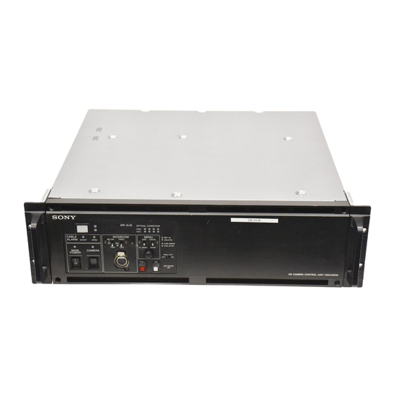
Page 7: Locations And Functions Of Parts
Locations and Functions of Parts HDCU2000 Front Panel 2 3 4 a Red tally indicator e INTERCOM audio input/output and control block Lights in red when this unit receives a red tally signal. When MIC/PGM (microphone/program) switch the CALL button on the MSU-1000 series Master Setup Unit, RCP-1000 series Remote Control Panel, etc., is pressed, this... - Page 8 To use a headset with a plug other than an XLR 5-pin plug, switch is turned on. Press the top side to turn on the video consult a Sony service or sales representative. camera and the bottom side to turn it off.
-
Page 9: Hdcu2000 Rear Panel
SD signal. the OUTPUT3 and OUTPUT4 connectors can be superimposed character and marker signals. For details on the setup menu, contact a Sony service or sales Signals of the same format are output from the SDI 1 and SDI representative. - Page 10 Sony service or sales representative. or using the MSU-1000 series Master Setup Unit. n WF REMOTE (waveform monitor remote) connector For details on the setup menu, contact a Sony service or sales (D-sub 15-pin) representative. Used to attach to the appropriate connector on a recall-type...
- Page 11 Note Use of a D-sub case wider than 42 mm can cause interference at connectors 2, 4, 5. It is recommended that you use a JAE-made DA-C1-J10. r AUX REMOTE connector (round 8-pin) This is used to connect a sub-camera RCP for operating a sub-camera.
-
Page 12: Hdcu2500 Front Panel
HDCU2500 Front Panel a Red tally indicator When the second lamp from the right (green) is lighted: Lights in red when this unit receives a red tally signal. When Reception status is good. the CALL button on the MSU-1000 series Master Setup Unit, When the second lamp from the left (yellow) is lighted: RCP-1000 series Remote Control Panel, etc., is pressed, this Reception status is low. - Page 13 CANCEL/ENTER To use a headset with a plug other than an XLR 5-pin plug, consult a Sony service or sales representative. lever to the ENTER position. g CABLE ALARM indicators j Network indicator OPEN (red): Lights in red when a camera isn’t connected to...
-
Page 14: Hdcu2500 Rear Panel
For installation of an optional HKCU2007 3G/HD SDI Output or using the MSU-1000 series Master Setup Unit. Expansion Unit, HKCU1001 SD Encoder Unit, or HKCU1003 For details on the setup menu, contact a Sony service or sales Multi Interface Unit. representative. - Page 15 75 ohms. If the signal used is a 1.0 Vp-p, 75-ohm signal, it may be output from the PROMPTER For details on the setup menu, contact a Sony service or sales OUT connector of the video camera with a frequency representative.
-
Page 16: Internal Switches
VDA-A board’s connectors. is set to OFF, setting the POWER switch on the front panel to ON doesn’t turn on the unit. For details on installation, contact a Sony service or sales representative. HKCU2007 3G/HD SDI Output... -
Page 17: Hkcu1003 Multi Interface Unit (Optional)
EN-B board in the corresponding expansion slot on REF IN the front of the HDCU2000/2500. When either the VDA-A board or the VDA-B board is installed, you can insert the VDA- C board in an expansion slot on the rear panel of the HDCU2000/2500. - Page 18 Input an HD tri-level reference sync signal or SD reference sync signal (black burst signal) for the sequence-lock between the camera control units, to the upper of the two connectors. The input signal is output from the lower connector as is (loop- through output).
-
Page 19: Connections And Settings
RET CTRL (SLOT1) FRONT MIC AES/EBU LINE LINE +48V +48V TEST AUDIO IN DC IN 10.5-17V MONI Prompter/ Floor monitor HDCU2000 SDI OUT 2 SDI OUT 4 RETURN (SLOT1) (SLOT1) INPUT SDI 1-4 LINK-A LINK-B Network cable Monitor LINK-A LINK-B... - Page 20 AES/EBU LINE LINE +48V +48V TEST AUDIO IN DC IN 10.5-17V MONI Prompter/ Floor monitor SDI OUT 3 RETURN HDCU2000 (SLOT1) INPUT SDI 1-4 Network cable Monitor (3G-SDI) Switcher (3G-SDI) RET (SD-SDI/HD-SDI/3G-SDI) RET (SD-SDI/HD-SDI/3G-SDI) MSU-1000/1500 RET (SD-SDI/HD-SDI/3G-SDI) Master Setup Unit...
-
Page 21: Coaxial Connection System
COAXIAL Connection System The camera and the camera control unit is connected via two Note coaxial cables in place of an optical fiber cable, and Do not connect an optical fiber cable in a COAXIAL connection transmission is achieved with HD-SDI. system. -
Page 22: Dual-Camera System
AES/EBU LINE LINE +48V +48V TEST AUDIO IN DC IN 10.5-17V SDI 2 MONI Primary camera control unit REFERENCE HD TRUNK PROMPTER (HDCU2000) BNC cables BNC cable (HD-SDI) Secondary camera (HDC2500) LEVEL PROD LEVEL PROD REAR INCOM REAR INCOM FRONT... -
Page 23: Sub-Camera System
Sub-Camera System Use an HDC-P1, etc. as the sub camera, which can be Note controlled via the AUX REMOTE connector of the HDCU2000. AES/EBU signal cannot be used between the camera and camera control unit. Connection example Main camera (HDC2000) -
Page 24: Status Display
Camera settings Status Display Page 1 The CCU system status can be monitored using a picture monitor connected to the PIX output. 1/2000 For information on monitoring and changing settings, see “Setup Menu” on page 29. Displaying the Status Screen The status screen is controlled using the knob and levers in ND :1 F:4.7 EX CC:B... - Page 25 FLR: Flare balance R/G/B/Master value The name of the board connected to the unit’s front panel and DTL: Detail level that board’s self-diagnostic results are displayed. HDCU 2000 Page 3 Slot A to D Slot 1 to 6 HDCU2500 Slot A to C S D Ma t ri x : ON C C Re d uc t io n: ON Slot 1 to 3...
- Page 26 Page 3 Page 3 * S y s t e m Di a g 3 /3 * 5 / 2 0 * Network Diag 3/3* 8/20 I n t e r c o m C C U S ys t em I P Addr :192.168.
- Page 27 R e a r :H I F P ow e r : O K Status of the board inserted in Slot4 (HDCU2000 only) 1 & 2: Output format of Output 1 & 2 3 & 4: Output format of Output 3 & 4...
- Page 28 Status of the board inserted in Slot5 Camera hardware diagnostics (HDCU2000 only) * CAMERA Diag* 19/20 * E N - B ( S l ot 5 ) D ia g * 1 6 / 2 0 ALL BOARD OK S ub - R e f :N o ne...
-
Page 29: Setup Menu
The pointer (,) changes to a flashing question mark (?). Setup Menu Flashing <OUTPUT SELECT> ?S01 TOP The CCU system and peripheral settings can be checked and modified using a picture monitor connected to the PIX output. OUTPUT:*CAMERA TEST1 TEST2 Changing Menu Item Settings PIX:*ENC R&G... - Page 30 Turn the CONTROL knob to move the cursor to the desired character, then press the CONTROL knob. Repeat steps 1 and 2 to enter other characters. • Select INS to insert a space character at the cursor position. • Select DEL to delete the character at the cursor position.
-
Page 31: Menu Tree
Menu Tree SYSTEM OPERATION menu CCU CONFIGURATION menu OUTPUT SELECT OUTPUT COLOR BAR HD-BAR (S01) (C01) MF CB GENLOCK PHASE CONTROL SLOPE REFERENCE (S02) SD-BAR GENLOCK BAR-CHARA H STEP GRAY COARSE MOVING SYMBOL V PHASE TYPE SUB-REF SIZE MULTI FORMAT FREQUENCY BAR CHARACTER BAR CHARACTER... - Page 32 SPIRIT LEVEL INDICATOR PROMPT/TRUNK 1 PROMPTER CH TRUNK LINE (C21) REVERSE (C10) H POSITION V POSITION BOARD SETUP BOARD SELECT RATE EMBED AUDIO AUX REMOTE (C22) NETWORK TRUNK META DATA EMB PROMPT/TR UNK 2 MODE PAYLOAD ID (C11) RATE INTER LOCK OTHERS ASSIGNABLE HD PROMPTER...
- Page 33 NETWORK SETTINGS menu IP ADDR SET HOST IP ADDRESS SUB NET MASK (N01) DEFAULT GATEWAY LAN SETTING AUTO NEGOTIATION (N02) AUTO MDIX CONNECT CONFIGURATION CONNECTION SPEED DUPLEX MODE MDI/MDIX SELECT LINK CONDITION CNS SETTING CNS MODE (N03) MCS MODE CCU NO MASTER IP ADDRESS NETWORK RESET ALL RESET...
-
Page 34: Menu List
Menu List Note The following conventions are used in the menu list table. Settings column values (e.g. ON, OFF, 0): Default settings Execute via ENTER: Press the CONTROL knob or move the CANCEL/ENTER lever to the ENTER position to execute. SYSTEM OPERATION menu SYSTEM OPERATION Page name... - Page 35 SYSTEM OPERATION Page name Item Settings Description Page No. <MULTI FORMAT> FREQUENCY 1.001, 1.000 Selects the operating frequency. (525NTSC), (625PAL) Note CAMERA FORMAT When FREQUENCY is set to Selects the transmission format. FREQUENCY or 1.001: 1080/59.94I, 1080/ CAMERA FORMAT mode 29.97PsF, 1080/59.94P, 1080/ setting changes take effect 23.98PsF, 720/59.94P, 1080/...
- Page 36 Selects the output format for expansion slot 3’s SDI OUT connector. SLOT4 (board name) Output format* Selects the output format for expansion slot 4’s SDI OUT connector. (HDCU2000 only) SLOT5 (board name) Output format* Selects the output format for expansion slot 5’s SDI OUT connector. (HDCU2000 only)
- Page 37 1080/59.94I 1080/29.97PsF 1080/23.98PsF 1080/59I 720/59P (RGB444) (RGB444) (RGB444) (2×) (2×) Slot1 1&2 1080/59.94I 1080/29.97PsF 1080/23.98PsF 1080/59I 720/59P (RGB444) (3G) (RGB444) (3G) (RGB444) (3G) (2×) (3G) (2×) (3G) Slot1 3&4 M1080/59.94I M1080/29.97PsF C1080/23.98PsF C1080/59I C720/59P (RGB444) (3G) (RGB444) (3G) (RGB444) (A) (2×) (3G) (2×) (3G) Slot2 1&2 1080/59.94I...
- Page 38 SYSTEM OPERATION Page name Item Settings Description Page No. <SD ASPECT> SD ASPECT SQUEEZE, EDGE CROP, LETTER Selects the SD output aspect. SD LB SEL 16:9, 15:9, 14:9, 13:9 Selects the LETTER BOX aspect ratio. H-POSITION –99 to 99, (–99) to (99) 0 Sets the horizontal position.
- Page 39 OUTPUT FORMAT RETURN FORMAT 1080/59.94I 1080/59.94I (PsF), 525/59.94I (PsF), NTSC 1080/29.97PsF 1080/59.94P 1080/59.94P , 1080/59.94I (PsF), 720/59.94P , 525/59.94I (PsF), NTSC 1080/23.98PsF 1080/23.98PsF, 1080/59.94I (PsF), 525/59.94I (PsF), NTSC 720/59.94P 720/59.94P, 525/59.94I (PsF), NTSC 1) 2) 1080/59.94I (RGB444) 1080/59.94I (PsF) (RGB444) , 1080/59.94I (PsF), 525/59.94I (PsF), NTSC 1080/29.97PsF (RGB444) 1) 2)
- Page 40 SYSTEM OPERATION Page name Item Settings Description Page No. <RETURN SETUP> FRAME SYNCHRO OFF, ON Set the FRAME SYNCHRO function for the return signal to on/off. SD-RETURN MATRIX OFF, ON Turn the HD matrix to the SD return signal on/off. LB LINE 360, 364 Set the effective line setting for letterbox.
- Page 41 CCU CONFIGURATION menu CONFIGURATION Page name Item Settings Description Page No. <COLOR BAR> HD-BAR BAR 16:9 (100%), BAR 16:9 Sets an HD output color bar. (75%), SMPTE 16:9 (BLACK), SMPTE 16:9 (–I/Q), BAR 4:3 (100%), BAR 4:3 (75%), SMPTE 4:3 (BLACK), SMPTE 4:3 (–I/Q), MF-ARIB (75%), MF-ARIB (100%), MF-ARIB (+I), MF-SMPTE (–I,Q), MF-SMPTE (75%,Q), MF-SMPTE...
- Page 42 <AUDIO OUT> DELAY 0 to 3840FS Sets the camera’s microphone output phase. AES/EBU OUT MIC 1/2, AES, EBU Selects the MIC OUT DIGITAL output. (HDCU2000 only) ANALOG OUT MIC 1/2, AES, EBU Selects the MIC OUT ANALOG output. CH1 LEVEL 0, +4, –20...
- Page 43 CONFIGURATION Page name Item Settings Description Page No. <INTERCOM> INTERCOM CH 1CH, 2CH Selects the intercom channel number. SYSTEM INTERFACE PRODUCER 4WIRE, RTS, CLEAR COM Sets the producer line intercom system. CANCEL LVL –99 to 99 0 Sets the side tone cancel level. Connects to a 200 Ω...
- Page 44 CONFIGURATION Page name Item Settings Description Page No. <PROMPT/TRUNK 2> NETWORK TRUNK MODE (OFF), OFF, NETWORK, Sets the mode for the network trunk. NETWORK + VIDEO RATE ---, (100Mbps), (1Gbps) Sets the rate for the network trunk line. HD PROMPTER (ENABLE), (DISABLE) Displays “ENABLE”...
- Page 45 CONFIGURATION Page name Item Settings Description Page No. <MENU SETTINGS> RESUME ON, OFF Turns ON/OFF the menu mode resume page display function. ALARM JUMP ON, OFF Turns ON/OFF the error-related page display function for when an error occurs while in menu mode.
- Page 46 CONFIGURATION Page name Item Settings Description Page No. <TRANSMIT> TRANSMIT AUTO, HIGH BIT RATE, HD-SDI, Sets the optical transmission rate between a camera (HD-SDI) and CCU. CABLE CAMERA CABLE, COAX Sets the transmission method between a camera and CCU. TRIAX ADAPTER TYPE DISABLE, A-TRIAX, D-TRIAX Sets the TRIAX adapter type.
- Page 47 NETWORK SETTINGS Page name Item Settings Description Page No. <LAN SETTING> AUTO NEGOTIATION ON, OFF Selects whether to automatically set the connection speed and communication system according to the device connected. AUTO MDIX ON, OFF Sets the communication line. CONNECT CONFIGURATION CONNECTION 10M, 100M...
-
Page 48: Appendix
• Where it is subject to extremes of temperature (operating CCU:SDI NG Rear SDI board power supply temperature: +5 to +40°C (41 to 104°F) for HDCU2000, –10 error to +40°C (14 to 104°F) for HDCU2500). Note that in summer CCU:PS FAN NG... -
Page 49: Specifications
NETWORK TRUNK 8-pin (1) Input connectors AC IN (1), 100/120/220-240 V HDCU2000 (To change to a different power supply, contact a Sony service or sales representative.) General SDI RET IN BNC-type (4) Power supply 100/120/220-240 V AC, 50/60 Hz 3G-SDI: SMPTE 424M/425M, 2.970 Gbps/ 2.967 Gbps... -
Page 50: Hdcu2500
HD/SD SDI OUTPUT BNC-type (2) HDCU2500 (MONI) HD-SDI: SMPTE 292M, 0.8 Vp-p, 75 ohms, 1.485 Gbps/1.4835 Gbps General SD-SDI: SMPTE 259M, 0.8 Vp-p, 75 ohms, 270 Mbps Power supply 100 to 240 V AC, 50/60 Hz HD-SDI/SD-SDI and character ON/OFF Current consumption 4.1 A (max.) selectable... - Page 51 Input connectors CHARACTER/SYNC BNC-type (1) HD SYNC: HD, BTA-S001, tri-level sync, AC IN (1), 100 to 240 V AC 0.6 Vp-p, 75 ohms RET 1, 2, 3 BNC-type (3) SD SYNC: SD, composite sync, 0.3 Vp-p, 3G-SDI: SMPTE 424M/425M, 2.970 Gbps/ 75 ohms 2.967 Gbps CHARACTER: VBS, 1 Vp-p, 75 ohms,...
-
Page 52: Hkcu2007 (Optional)
Supplied accessories Always verify that the unit is operating properly before use. 4-pin connector (1) SONY WILL NOT BE LIABLE FOR DAMAGES OF ANY KIND INCLUDING, BUT NOT LIMITED TO, Design and specifications are subject to change without COMPENSATION OR REIMBURSEMENT ON ACCOUNT notice. - Page 53 The material contained in this manual consists of information that is the property of Sony Corporation and is intended solely for use by the purchasers of the equipment described in this manual. Sony Corporation expressly prohibits the duplication of any...
- Page 54 Sony Corporation HDCU2000 (UC/CE/E) HDCU2500 (SY) 4-413-603-04(1) © 2011...
Need help?
Do you have a question about the HDCU2000 and is the answer not in the manual?
Questions and answers