
Related Manuals for Sony HDCU2080


Summary of Contents for Sony HDCU2080
- Page 1 HD CAMERA CONTROL UNIT HDCU2080 3G/HD SDI OUTPUT EXPANSION UNIT HKCU2007 SD ENCODER UNIT HKCU1001 MULTI INTERFACE UNIT HKCU1003 OPERATION MANUAL [English] 1st Edition...
- Page 2 Before operating the unit, please read this manual thoroughly and retain it for future reference. For the HDCU2080 WARNING To reduce the risk of fire or electric shock, do not expose this apparatus to rain or moisture. To avoid electrical shock, do not open the cabinet.
-
Page 3: Table Of Contents
Menu Tree ..............23 Menu List ............... 25 Appendix ..............35 Notes on Use..............35 Error Messages ............. 35 Specifications ............36 HDCU2080 ..............36 HKCU2007 (optional) ............ 37 HKCU1001 (optional) ............ 37 HKCU1003 (optional) ............ 37 Table of Contents... -
Page 4: Overview
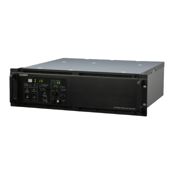
External reference signals Overview The HDCU2080 can be locked to an external reference signal. Either an HD tri-level sync signal or an SD sync (black burst) signal may be used as the reference signal. The HDCU2080 Camera Control Unit is connected to a Sony Built-in down converter HD-series high-definition video camera. - Page 5 Character monitor signal output The results of the HDCU2080 self-diagnosis and setup menu can be obtained with a text display by character signal output. Rack mountable This unit may be installed in a standard EIA 19-inch rack (three units high).
-
Page 6: System Configuration
MSU-1000 series Master Setup Unit Remote Control Panel LAN cable LAN cable Camera Control Unit Camera Optical fiber cable HDC2580 HD Color Video HDCU2080 Camera HD Camera Control Unit HDVF-20A/200/C30WR/ C35W HD Electronic Viewfinder Camera Control Unit Camera Optical fiber cable... -
Page 7: System Operation Example
System Operation Example Image monitor HD-SDI Video monitor HDC2580 LCD monitor HDCU2080 LAN cable LAN cable MSU-1000 series HD-SDI HDC2580 HDCU2080 CCA-5 cable RCP-1000 series CCA-5 cable System Configuration... -
Page 8: Locations And Functions Of Parts
Locations and Functions of Parts Front Panel 2 3 4 a Red tally indicator e INTERCOM audio input/output and control block Lights in red when this unit receives a red tally signal. When MIC/PGM (microphone/program) switch the CALL button on the MSU-1000 series Master Setup Unit, RCP-1000 series Remote Control Panel, etc., is pressed, this INTERCOM (intercom select) switch indicator will go out if previously lit, and light up if previously... - Page 9 To use a headset with a plug other than an XLR 5-pin plug, switch is turned on. Press the top side to turn on the video consult a Sony service or sales representative. camera and the bottom side to turn it off.
-
Page 10: Rear Panel
Rear Panel a Expansion slots For details on the setup menu, contact a Sony service or sales representative. For installation of an optional HKCU2007 3G/HD SDI Output Expansion Unit, HKCU1001 SD Encoder Unit, or HKCU1003 Refer also to the Master Setup Unit manual. - Page 11 WF REMOTE (waveform monitor remote) connector or using the MSU-1000 series Master Setup Unit. (D-sub 15-pin) For details on the setup menu, contact a Sony service or sales Used to attach to the appropriate connector on a recall-type representative.
-
Page 12: Hkcu2007 3G/Hd Sdi Output Expansion Unit (Optional)
VDA-A board’s connectors. • The HDCU2080 does not support 3G digital optical output. For details on installation, contact a Sony service or sales representative. The HKCU2007 3G/HD SDI Output Expansion Unit consists of a DRX front board and an HIF rear board. -
Page 13: Hkcu1003 Multi Interface Unit (Optional)
When you use either the VDA-A board or the VDA-B board, insert the EN-B board in the corresponding expansion slot on the front of the HDCU2080. When either the VDA-A board or the VDA-B board is installed, you can insert the VDA-C board in an expansion slot on the rear panel of the HDCU2080. - Page 14 VDA-C Board VDA-C R/R-Y B/B-Y a VBS (composite video signal output) connector (BNC- type) The signal from the video camera may be output as an analog composite signal. b R/R-Y, G/Y, B/B-Y (component video signal output) connectors (BNC-type) The signal from the video camera may be output as a R/R-Y, G/Y, B/B-Y component signal or an RGB component signal.
-
Page 15: Connections And Settings
PROMPTER/ LINE LINE +48V +48V TEST AUDIO IN DC IN 10.5-17V GEN LOCK MONI Floor monitor SDI OUT 3 RETURN HDCU2080 (SLOT2) INPUT SDI 1-4 Network cable Monitor (HD-SDI) Switcher (HD-SDI) RET (SD-SDI/HD-SDI) RET (SD-SDI/HD-SDI) MSU-1000/1500 RET (SD-SDI/HD-SDI) Master Setup Unit... -
Page 16: Status Display
Camera settings Status Display Page 1 The CCU system status can be monitored using a picture monitor connected to the PIX output. 1 /2 000 O FF For information on monitoring and changing settings, see “Setup Menu” on page 21. Displaying the Status Screen The status screen is controlled using the knob and levers in ND: 1 F: 4.7 EX... - Page 17 Page 3 Slot A to D Slot 1 to 6 Camera system diagnostics S D M a t r i x : ON C C R e d u c t i o n: O N C or i n g : 0 Le v e l : 35 Page 1 S D D e t a i l : ON L e v e l : 0 Co m b...
- Page 18 Page 3 Page 3 * Sy s t e m D i a g 3 / 3 * 5 / 20 *Ne tw ork Di ag 3/ 3* 8 /20 I nt e r c o m C C U P r i v a t e IP Ad dr :19 2.
- Page 19 CCU DTX board diagnostics Front: Status of power supply to the board installed in option slot 2 and the board name PLD Version: PLD version of the board installed in option slot * D T X D i a g * 11 /2 0 2 and the board name Rear: Status of power supply to the rear board and board...
- Page 20 Status of the board inserted in Slot5 Camera hardware diagnostics * EN - B ( S l o t 5 ) D i a g * 1 6 / 20 *CA ME RA Dia g* 19 /20 AL L B OA RD OK S ub - R e f : N o n e U n k n o w n Fr o n t : E N 2 - B...
-
Page 21: Setup Menu
The pointer (,) changes to a flashing question mark (?). Setup Menu Flashing <O UT PUT SE LE CT> ? S01 TO P The CCU system and peripheral settings can be checked and modified using a picture monitor connected to the PIX output. O UT PUT :*C AM ERA B AR T ES T1... - Page 22 Turn the CONTROL knob to move the cursor to the desired character, then press the CONTROL knob. Repeat steps 1 and 2 to enter other characters. • Select INS to insert a space character at the cursor position. • Select DEL to delete the character at the cursor position.
-
Page 23: Menu Tree
Menu Tree SYSTEM OPERATION menu CCU CONFIGURATION menu OUTPUT SELECT OUTPUT COLOR BAR HD-BAR (S01) (C01) MF CB GENLOCK PHASE CONTROL SLOPE REFERENCE (S02) SD-BAR GENLOCK BAR-CHARA H STEP GRAY COARSE BAR CHARACTER BAR CHARACTER V PHASE (C02) ALL CLEAR SUB-REF MONITOR 1 CHARACTER... - Page 24 NETWORK SETTINGS menu PROMPT/TRUNK PROMPTER IP ADDR SET HOST IP ADDRESS (C10) TRUNK SETTINGS SUB NET MASK (N01) DEFAULT GATEWAY TRANSMIT LAN SETTING AUTO NEGOTIATION CABLE (N02) AUTO MDIX AUX REMOTE CONNECT CONFIGURATION VIDEO SETUP SETUP CONNECTION SPEED (C11) SD BLK CLP DUPLEX MODE Q FILTER MDI/MDIX SELECT...
-
Page 25: Menu List
Menu List Note The following conventions are used in the menu list table. Settings column values (e.g. ON, OFF, 0): Default settings Execute via ENTER: Press the CONTROL knob or move the CANCEL/ENTER lever to the ENTER position to execute. SYSTEM OPERATION menu SYSTEM OPERATION Page name... - Page 26 SYSTEM OPERATION Page name Item Settings Description Page No. <OUTPUT FORMAT> CAMERA TRANSMIT 1080/50I Displays the output format. This setting works in conjunction with CAMERA FORMAT. SLOT1 (board name) 1&2 Output format* Selects the output format for expansion slot 1’s SDI OUT1/2 connector.
- Page 27 SYSTEM OPERATION Page name Item Settings Description Page No. <RETURN FORMAT> RET1 1080/50I (PsF), 625/50I (PsF), PAL Sets the return signal input format. SQUEEZE, EDGE CROP, LETTER Sets input format, aspect ratio, and letterbox mode. RET2 BOX, RET3 16:9, 15:9, 14:9, 13:9 RET4 AUTO SCAN Execute via EXEC.
- Page 28 CCU CONFIGURATION menu CONFIGURATION Page name Item Settings Description Page No. <COLOR BAR> HD-BAR BAR 16:9 (100%), BAR 16:9 Sets an HD output color bar. (75%), SMPTE 16:9 (BLACK), SMPTE 16:9 (–I/Q), BAR 4:3 (100%), BAR 4:3 (75%), SMPTE 4:3 (BLACK), SMPTE 4:3 (–I/Q), MF-ARIB (75%), MF-ARIB (100%), MF-ARIB (+I), MF-SMPTE (–I,Q), MF-SMPTE (75%,Q), MF-SMPTE...
- Page 29 CONFIGURATION Page name Item Settings Description Page No. <MONITOR 2> LEVEL GATE ---, 1&2, 1, 2, OFF 1&2: Displays level gate 1 & 2. 1: Displays level gate 1. 2: Displays level gate 2. ---: Displayed when camera not connected, video output not set to CAMERA, or video output is set to CAMERA and GATE MARKER is ON.
- Page 30 CONFIGURATION Page name Item Settings Description Page No. <INTERCOM> INTERCOM CH 1CH, 2CH Selects the intercom channel number. SYSTEM INTERFACE PRODUCER 4WIRE, RTS, CLEAR COM Sets the producer line intercom system. CANCEL LVL –99 to 99 0 Sets the side tone cancel level. Connects to a 200 Ω...
- Page 31 CONFIGURATION Page name Item Settings Description Page No. <PROMPT/TRUNK> PROMPTER 1CH, 2CH Sets the number of prompter lines. TRUNK SETTINGS (38Kbps), (19Kbps) Displays the TRUNK line. (Display only) 1CH, 2CH Sets the number of channels to be used. 232C, 422A Sets the communication line mode.
- Page 32 CONFIGURATION Page name Item Settings Description Page No. <MENU SETTING> RESUME ON, OFF Turns ON/OFF the menu mode resume page display function. ALARM JUMP ON, OFF Turns ON/OFF the error-related page display function for when an error occurs while in menu mode.
- Page 33 CONFIGURATION Page name Item Settings Description Page No. <OTHERS> BOARD SELECT DRX1, DRX2, DRX3, DRX4, RC Selects the board to set. EMBED AUDIO ON, OFF Sets superimposition of audio data to ON/OFF. META DATA EMB OFF, ON Sets superimposition of metadata to ON/OFF. VIDEO PAYLOAD NEW, OLD Sets the VIDEO ID.
- Page 34 NETWORK SETTINGS Page name Item Settings Description Page No. <LAN SETTING> AUTO NEGOTIATION ON, OFF Selects whether to automatically set the connection speed and communication system according to the device connected. AUTO MDIX ON, OFF Sets the communication line. CONNECT CONFIGURATION CONNECTION 10M, 100M...
-
Page 35: Appendix
Error Messages Appendix When an error is detected in this unit or the camera, the ALARM indicator turns on and an error message is displayed on this unit. Notes on Use Error message Indication CCU:GEN LOCK NG External reference sync error Use and storage locations CCU:DRX NG Front DRX board power supply,... -
Page 36: Specifications
Input connectors Specifications AC IN (1), 100/120/220-240 V (To change to a different power supply, contact a Sony service or sales representative.) HDCU2080 SDI RET IN BNC-type (4) HD-SDI: SMPTE 292M, 1.485 Gbps/ 1.4835 Gbps General SD-SDI: SMPTE 259M, 270 Mbps... -
Page 37: Hkcu2007 (Optional)
3/4) VDA-A/B/C board: Approx. 0.10 kg Output connectors Note VDA-A board The HDCU2080 does not support 3G-SDI. BNC-type (2), 1.0 Vp-p, 75 ohms, VBS Design and specifications are subject to change without PIX OUT BNC-type (1), VBS/R/G/B (VBS 1.0 Vp-p, 75 ohms) notice. - Page 38 Design and specifications are subject to change without notice. Note Always verify that the unit is operating properly before use. SONY WILL NOT BE LIABLE FOR DAMAGES OF ANY KIND INCLUDING, BUT NOT LIMITED TO, COMPENSATION OR REIMBURSEMENT ON ACCOUNT OF THE LOSS OF PRESENT OR PROSPECTIVE...
- Page 39 The material contained in this manual consists of information that is the property of Sony Corporation and is intended solely for use by the purchasers of the equipment described in this manual. Sony Corporation expressly prohibits the duplication of any...
- Page 40 Sony Corporation Printed in Japan HDCU2080 (CN) 2012.07 08 4-439-363-01(1) © 2012...
Need help?
Do you have a question about the HDCU2080 and is the answer not in the manual?
Questions and answers