Sony HDCU1000 Operation Manual
Hd camera control unit
Hide thumbs
Also See for HDCU1000:
- Maintenance manual (334 pages) ,
- Installation manual (102 pages) ,
- Maintenance manual (150 pages)

Related Manuals for Sony HDCU1000


Summary of Contents for Sony HDCU1000
- Page 1 HD CAMERA CONTROL UNIT HDCU1000 HDCU1500 SD ENCODER UNIT HKCU1001 MULTI INTERFACE UNIT HKCU1003 SDI OUTPUT EXPANSION UNIT HKCU1005 OPERATION MANUAL [Japanese/English] 1st Edition (Revised 3)
- Page 3 ........................4 ........................5 ..................7 ...........................8 ....................... 10 ....................10 ..................11 ................12 ...................13 ....................... 14 ....................15 ...................15 ...................16 ...................19 ...................20 ........22 ......23 ..........25 ..................26 ................26 ................26 ......................27 .........................29 ....................29 ....................31 ..................32 ..................32 ..................33...
- Page 4 • • • • •...
- Page 5 • •...
- Page 6 • • • •...
- Page 7 μ –29...
- Page 8 • • • • • • • • • • •...
- Page 13 PANEL STANDARD MONITOR TEST BARS CLOSE ACTIVE START/STOP MEMORY 5600K AUTO SKIN BLACK KNEE STICK KNEE DETAIL GAMMA SATURATION POWER CABLE WHITE ALRAM FUNCTION OPEN MAIN SHORT BLACK MAINTE NANCE INCOM PROD PRIV SCENE AUTO IRIS/MB ACTIVE MASTER IRIS BLACK PAINT IRIS ALARM...
- Page 14 • • • •...
- Page 19 POWER CABLE ALARM OPEN MAIN SHORT INCOM PROD PRIV HD CAMERA CONTROL UNIT...
- Page 22 EN-A NTSC SC PHASE DELAY...
- Page 23 • VDA-A • • EN-B NTSC REF IN LOCK SC PHASE DELAY...
- Page 24 VDA-B FRAME REF IN VDA-A...
- Page 25 VDA-C 1080 R/R-Y 720P B/B-Y SDI OUT...
- Page 26 PGM ON CABLE ALARM SHORT OPEN MAIN CAMERA PGM OFF INTERCOM POWER POWER DYNAMIC CARBON POWER CABLE ALARM OPEN MAIN SHORT INCOM PROD PRIV...
- Page 27 REFERENCE REF IN LOCK H PHASE DELAY...
- Page 28 POWER LOCK CAM POWER SYSTEM CHARACTER DISP /1.001 MENU LINE DELAY 2WIRE CANCEL CANCEL ENTER PROD...
- Page 29 1080 720P • • •...
- Page 31 POWER CABLE ALRAM OPEN MAIN SHORT INCOM PROD PRIV HD CAMERA CONTROL UNIT • • •...
- Page 33 • •...
- Page 34 English For the HDCU1000/HDCU1500 WARNING: THIS WARNING IS APPLICABLE FOR USA ONLY. WARNING If used in USA, use the UL LISTED power cord specified below. DO NOT USE ANY OTHER POWER CORD. To reduce the risk of fire or electric shock,...
- Page 35 La conformité à ces directives implique la conformité aux Wenn Sie Fragen zur Verwendung von Netzkabel/ Geräteanschluss/Stecker haben, wenden Sie sich bitte an normes européennes suivantes: qualifiziertes Kundendienstpersonal. • EN60950-1: Sécurité des produits • EN55103-1: Interférences électromagnétiques (émission) For customers in the USA •...
- Page 36 Daten der Laserdiode For the HKCU1001/HKCU1003/HKCU1005 Wellenlänge: 1310 ±40 nm For the customers in the U.S.A. Emissionsdauer: Pulsmodulation μW This equipment has been tested and found to comply with Laser-Ausgangsleistung: 141 –29 the limits for a Class A digital device, pursuant to Part 15 of the FCC Rules.
- Page 37 (89/336/CEE) émise par la Commission de la Communauté Européenne. La conformité à cette directive implique la conformité aux normes européennes suivantes: • EN55103-1: Interférences électromagnétiques (émission) • EN55103-2: Sensibilité électromagnétique (immunité) Ce produit est prévu pour être utilisé dans les environnements électromagnétiques suivants: E1 (résidentiel), E2 (commercial et industrie légère), E3 (urbain extérieur) et E4 (environnement EMC contrôlé,...
-
Page 38: Table Of Contents
SD Signal System ..............42 HD/SD Signal System ..............43 Example of Mounting an RM-B750.........44 Locations and Functions of Parts ........45 HDCU1000 Front Panel ............45 HDCU1000 Rear Panel ............46 HDCU1500 Front Panel ............49 HDCU1500 Rear Panel ............50 HKCU1001 SD Encoder Unit (optional)........52 HKCU1003 Multi Interface Unit (optional)......53... - Page 39 HKCU1003 Multi Interface Unit Only after it has been verified that an appropriated camera This board consists of three types of interface board and is attached, the normal 240 V AC (HDCU1000) or 180 V provides: Overview...
- Page 40 Wide range of audio functions The HDCU1000/HDCU1500 has connectors for two- channel microphone outputs, a digital audio output (only for the HDCU1000), and a program audio input. Further, the HDCU1000/HDCU1500 can use an intercom system with two independent channels, and supports four-wire and RTS/Clear-Com intercom systems.
-
Page 41: System Configuration
MSU-900 series Master Setup Unit Control Panel CNU-700 Camera Command Network Unit Camera Control Unit 1 Camera 1 Optical fiber cable HDC1000 HD Color Video HDCU1000 HDCU1500 Camera HD Camera Control Unit HD Camera Control Unit HDVF-9900 HD Electronic Viewfinder Camera Control Unit 2... -
Page 42: Sd Signal System
SD Signal System HDCU1000 VCS-700 PIX/WF + HKCU1001/HKCU1003 HDC1000 HDCU1500 + HKCU1001/HKCU1003 CNU-700 HDCU1000 MSU-900 series + HKCU1001/HKCU1003 HDC1000 HDCU1500 + HKCU1001/HKCU1003 SD-SDI HDCU1000 + HKCU1001/HKCU1003 HDC1500 HDCU1500 + HKCU1001/HKCU1003 HDCU1000 + HKCU1001/HKCU1003 HDC1500 RCP series HDCU1500 + HKCU1001/HKCU1003 System Configuration... -
Page 43: Hd/Sd Signal System
HD/SD Signal System HDCU1000 VCS-700 PIX/WF + HKCU1001/HKCU1003 HDC1000 MSU-900 series CNU-700 HDCU1500 + HKCU1001/HKCU1003 HDCU1000 + HKCU1001/HKCU1003 HDC1000 SD-SDI HDCU1500 + HKCU1001/HKCU1003 HDCU1000 + HKCU1001/HKCU1003 HDC1500 RCP series HDCU1500 + HKCU1001/HKCU1003 SD-SDI HDCU1000 + HKCU1001/HKCU1003 HDC1500 HDCU1500 + HKCU1001/HKCU1003... -
Page 44: Example Of Mounting An Rm-B
HDCU1500 + RM-B750 Remote Control Unit An RM-B750 Remote Control Unit can be mounted on the HDCU1500 and be used as a control panel to control the HDCU1500. For details on mounting, contact a Sony service or sales representative. System Configuration... -
Page 45: Locations And Functions Of Parts
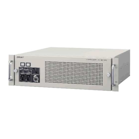
Locations and Functions of Parts HDCU1000 Front Panel 1 Red tally indicator 2 Green tally indicator 3 MIC switch 4 INTERCOM level control 8 INTERCOM connector 7 CAMERA POWER switch and indicator 6 MAIN POWER switch and indicator 5 CABLE ALARM indicators a Red tally indicator OPEN (red): Lights in red when a camera isn’t connected... -
Page 46: Hdcu1000 Rear Panel
TRUNK LINE connector qd I/O PORT connector a SDI OUTPUT area (BNC-type) For details on the setup menu, contact a Sony service or The signal from the video camera may be output as two sales representative. HD-SDI or SD-SDI signals. - Page 47 An aspect ratio may also be selected for SD signals. terminate the unused connector at 75 ohms. The type of reference signal is selected using the setup For details on the setup menu, contact a Sony service or menu, or using the MSU-900 series Master Setup Unit. sales representative.
- Page 48 SDI Output Expansion Unit. A sequence signal will be output when the SEQ button on the RCP-700 series Remote Control Panel is pressed, For details on installation, contact a Sony service or sales allowing simultaneous monitoring of the R, G, and B representative.
-
Page 49: Hdcu1500 Front Panel
To use a headset with a plug other than an XLR 5-pin plug, The MAIN indicator and the CAM indicator light when the consult a Sony service or sales representative. power switch is turned on. Pressing the CAM PW button of the master setup unit and the remote control panel turns off the video camera only;... -
Page 50: Hdcu1500 Rear Panel
0 RET1, RET2, RET3 connectors 9 INTERCOM/TALLY/PGM connector a SDI OUT1, SDI OUT2, SDI OUT3 connectors For details on the setup menu, contact a Sony service or (BNC-type) sales representative. The signal from the video camera may be output as three HD-SDI or SD-SDI signals. - Page 51 For safety, do not connect the connector for peripheral Unit. device wiring that might have excessive voltage to this port. For details on the setup menu, contact a Sony service or sales representative. ATTENTION Refer also to the Master Setup Unit manual.
- Page 52 The microphone input level may also be set using the setup HKCU1001 SD Encoder Unit menu. For details on the setup menu, contact a Sony (optional) service or sales representative. WF REMOTE (waveform monitor remote) connector Note The MIC REMOTE connector can be used as a WF...
- Page 53 When you use either the VDA-A board or the VDA-B board, insert the EN-B board in the corresponding expansion slot on the front of the HDCU1000/1500. When 3 WF OUT connector either the VDA-A board or the VDA-B board is installed, you can insert the VDA-C board in an expansion slot on the rear panel of the HDCU1000/1500.
- Page 54 c SC PHASE (subcarrier phase) switch VDA-B Board Used to adjust the SC phase with respect to the reference signal (black burst). This switch will return its original position when you release it. Press and hold the switch towards ADV to VDA-B FRAME REF IN...
-
Page 55: Hkcu1005 Sdi Output Expansion Unit (Optional)
The format of the SDI signal output through the HIF board can be set by the two up-and-down connectors. a SDI OUT1, SDI OUT2, SDI OUT3, SDI OUT4 For details on installation, contact a Sony service or sales representative. (HD/SD serial digital interface output 1-4) -
Page 56: Hdcu1500 Internal Switches
Headset microphone switch 2 (S5) When you set headset microphone switch 1 (S4) to DYNAMIC, also set this switch according to the type of HDCU1000 Internal Switches output of the headset microphone. ON: Unbalanced type The following switches are located inside the unit, behind... -
Page 57: Internal Boards
b Headset microphone switch 2 (S5) Insert the “Memory Stick” into the slot so that the labeled Set the switch according to the type of microphone of the side of the stick faces you. headset connected to the intercom connector on the front When the “Memory Stick”... - Page 58 a CCU POWER indicator b Menu control switch Lights when the power voltage inside the board is normal. Displays the setting status of this unit or the setup menu on the monitor connected to this unit. b CAM LOCK (camera lock) indicator DISP: Displays the setting status of this unit.
-
Page 59: Specifications
Specifications HDCU1000 General Power supply 100/120/220-240 V AC, 50/60 Hz (To change to a different power supply, contact a Sony service or sales representative.) Current consumption 5.4 A (max.) Peak inrush current (1)Power ON, current probe method: 70 A (240 V) - Page 60 REFERENCE INPUT HKCU1001 SD Encoder Unit BNC-type (2), loop-through output HKCU1003 Multi Interface Unit HD: SMPTE-274M, tri-level sync, HKCU1005 SDI Output Expansion Unit 0.6 Vp-p, 75 ohms CCA-5-3 Connection Cable (3 meter/10 feet) SD: Black burst CCA-5-10 Connection Cable (10 meter/33 feet) (NTSC: 0.286 Vp-p, 75 ohms) Expansion Board (PAL: 0.3 Vp-p, 75 ohms)
- Page 61 Design and specifications are subject to change without Dimensions notice. Unit: mm (inches) HDCU1500 General Power supply 100 to 240 V AC, 50/60 Hz Current consumption 4.1 A (max.) Standby power Approx. 5 W Peak inrush current (1)Power ON, current probe method: 30 A (240 V), 15 A (100 V) (2)Hot switching inrush current, measured in accordance with...
- Page 62 Optional accessories HD: SMPTE-274M, tri-level sync, 0.6 Vp-p, 75 ohms AC power cord: SD: Black burst USA and Canada: 1-551-812-XX (NTSC: 0.286 Vp-p, 75 ohms) Other countries: 1-782-929-XX (PAL: 0.3 Vp-p, 75 ohms) Power cord plug holder: or NTSC 10F-BB USA and Canada: 2-990-242-01 PROMPTER BNC-type (4), loop-through output,...
-
Page 63: Hkcu1001 (Optional)
Related equipment Dimensions (w/h/d) EN-B board: Approx. 19 × 110 × 226 mm HDC1000/HDC1500 HD Color Video Camera (3/4 × 4 3/8 × 8 7/8 inches) RCP-700 series Remote Control Panel VDA board (A/B/C): Approx. 19 × 98 × RM-B750 Remote Control Unit 159 mm MSU-900 series Master Setup Unit (3/4 ×... -
Page 64: Hkcu1005 (Optional)
Design and specifications are subject to change without notice. HKCU1005 (optional) General Power supply 5.3 W Operating temperature –10°C to +40°C (+14°F to +104°F) Storage temperature –20°C to +60°C (–4°F to +140°F) Dimensions (w/h/d) DRX board: Approx. 19 × 110 × 226 mm (3/4 ×... - Page 65 Ethernet is a registered trademark of Xerox Corporation. The material contained in this manual consists of information that is the property of Sony Corporation and is intended solely for use by the purchasers of the equipment described in this manual.
- Page 66 Sony Corporation HDCU1000/1500 Printed in Japan (J/UC/CE/SYL) 2006.10.13 3-903-898-04(1) © 2005...
Need help?
Do you have a question about the HDCU1000 and is the answer not in the manual?
Questions and answers