Sony HDCU4300 Operation Manual
Camera control unit networked media interface board hkcu-ip43f 12g-sdi extension kit hkcu-4002
Hide thumbs
Also See for HDCU4300:
- Service manual (170 pages) ,
- Operation manual (67 pages) ,
- Manual (30 pages)

Related Manuals for Sony HDCU4300


Summary of Contents for Sony HDCU4300
- Page 1 CAMERA CONTROL UNIT HDCU4300 NETWORKED MEDIA INTERFACE BOARD HKCU-IP43F 12G-SDI EXTENSION KIT HKCU-4002 OPERATION MANUAL [English] 1st Edition (Revised 2)
-
Page 2: Table Of Contents
Table of Contents Overview..............3 System Configuration ............4 Name and Function of Parts ........6 Front Panel...............6 Rear Panel ...............8 HKCU-IP43F Networked Media Interface Board (Option) .................9 HKCU-4002 12G-SDI Extension Kit (Option) ....9 Connections and Settings ........11 4K System Connection...........11 HD CUTOUT Video System ...........12 HFR Video System............13 HDR Video System ............15... -
Page 3: Overview
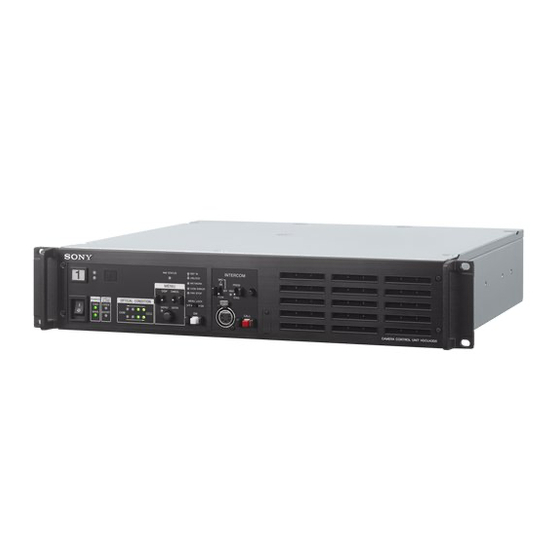
Overview The HDCU4300 Camera Control Unit connects to a HDC4300 Color Camera or HDC-P43 Multi Purpose Camera with an optical fiber cable, and carries out the processing of video signals from the camera and provides an interface with external equipment. -
Page 4: System Configuration
System Configuration Note Production of some of the peripherals and related devices shown in the figures may have been discontinued. For advice on choosing devices, please contact your Sony representative or dealer. HDC4300 connection example HDVF-EL75/L750/L770 Viewfinder PWS-100NM1 IP Live System Manager... - Page 5 HDC-P43 Multi Purpose Single-mode fiber Camera Lens cable (ST Optical fiber (for ENG/EFP) connector, 1 pair) CCA-5 cable HKCU-SM100 HDCU4300 CCU Extension RCP-1000 series Adapter Remote Control Panel V shoe USB drive Video Waveform VCT-14 monitor monitor Tripod Attachment...
-
Page 6: Name And Function Of Parts
Name and Function of Parts Front Panel a Red tally indicator On: When CNS SETTING in the NETWORK SETTING menu is set to either BRIDGE or MCS, this indicates Lights in red when this unit receives a red tally signal. You can that external control equipment (MSU-1000/1500 attach the supplied number plate here. - Page 7 This locks out operation of the front panel menu operation To use a headset with a plug other than an XLR 5-pin plug, area. consult a Sony service or sales representative. n Call button h MAIN POWER switch and indicator...
-
Page 8: Rear Panel
MSU-1000 series Master Connection Type and BNC Connector Assignment” (page 16). Setup Unit. For details on the setup menu, contact a Sony service or sales (LAN) connector (RJ-45 8-pin) representative. Used to connect to a LAN. Connect a LAN HUB (10BASE-T/ 100BASE-TX), using a LAN cable (shielded type of category 5 Refer also to the Master Setup Unit manual. -
Page 9: Hkcu-Ip43F Networked Media Interface Board (Option)
2 REFERENCE connectors (BNC-type) Input an HD tri-level reference sync signal or SD reference For details on how to select the signal, contact a Sony service sync signal (black burst signal, or black burst signal with 10 or sales representative. - Page 10 12G/6G-SDI output connectors These connectors are 12G-SDI output connectors or 6G-SDI output connectors. The output format is the same as the format set for SLOT1 of the HDCU4300. For details, see page 33.
-
Page 11: Connections And Settings
LINK-4 HDC4300 SDI-MONI Reference signal input SDI Monitor/Prompter REFERENCE CAMERA (Digital) HDCU4300 RETURN SDI IN SDI I/O 1 SDI I/O 2 SDI OUT SDI OUT Return signal input MSU-1000/1500 HD PROMPTER signal input Master Setup Unit HD TRUNK signal output... -
Page 12: Hd Cutout Video System
The cutout HD signal is output from SLOT1. the optional SZC-2001/2001M/2001W HD CUTOUT Software HD video down-converted from 4K signals can be output from in the HDCU4300. SLOT2, SLOT3, and SLOT4. The region that is cut out can be controlled using a mouse or Also, a wire frame indicating the cutout region can be other device connected to the HD CUTOUT Controller. -
Page 13: Hfr Video System
HFR Video System The unit can transfer HFR video and perform signal processing for the following formats according to the connected camera. Yes: Supported, No: Not supported HFR format Connected device HDC4300, HDC-P43 (without option) HDC4300, HDC-P43 (when SZC-4002 series installed on the unit) 1080/59.94P (2×) 1080/50P (2x) - Page 14 HDC4300 SDI-MONI Reference signal input SDI Monitor/Prompter REFERENCE CAMERA (Digital) RETURN SDI IN SDI I/O 1 HDCU4300 SDI OUT SDI OUT Return signal input MSU-1000/1500 HD PROMPTER signal input Master Setup Unit 3G SDI/HD RCP-1500/1501 HD SDI Monitor SDI Monitor Remote Control Panel For details about the assignments of BNC connectors of the unit, see “Relationship between Connection Type and BNC...
-
Page 15: Hdr Video System
LINK-4 HDC4300 SDI-MONI Reference signal input SDI Monitor/Prompter REFERENCE CAMERA (Digital) HDCU4300 RETURN SDI IN SDI I/O 1 SDI I/O 2 SDI OUT SDI OUT Return signal input MSU-1000/1500 HD PROMPTER signal input Master Setup Unit HD TRUNK signal output... -
Page 16: Relationship Between Connection Type And Bnc Connector Assignment
Relationship between Connection Type and BNC Connector Assignment The names of output interfaces in Table 1 correspond to BNC connector assignments in Table 2 (page 18). Check the output interface for the format you want to use in Table 1, then check the signal assignments to BNC connectors in Table 2. - Page 17 Operation Frame rate Slot1 Slot2/Slot3 mode Output format Output interface Output format HD HFR 59.94(8x) 1080/59.94i(8x), Quad-Link-2 1080/59.94i(1.5G), 720/59.94P(1.5G) , 525/59.94i 720/59.94P(8x) 50(8x) 1080/50i(8x), Quad-Link-2 1080/50i(1.5G), 720/50P(1.5G) , 625/50i 720/50P(8x) 59.94(6x) 1080/59.94i(6x), Triple-Link-2 1080/59.94i(1.5G), 720/59.94P(1.5G) , 525/59.94i 720/59.94P(6x) 50(6x) 1080/50i(6x), Triple-Link-2 1080/50i(1.5G), 720/50P(1.5G) , 625/50i...
-
Page 18: Paint Functions In Hdr Mode And Color Space
Some paint functions are disabled, depending on the HDR Disabled items can still be adjusted from the PAINT menu on MODE and COLOR SPACE settings on the HDCU4300. the camera or RCP/MSU, but the settings are not applied to the HDR video that is output from SLOT1. - Page 19 Paint function HDR MODE setting LIVE HDR Gamma ON/OFF (Fixed OETF) R/G/B/Master Step Gamma Black R/G/B/Master Black Gamma ON/OFF Range R/G/B/Master Flare ON/OFF R/G/B/Master Knee ON/OFF (Fixed OFF) Knee Point R/G/B/Master Knee Slope R/G/B/Master Auto Knee ON/OFF Auto Knee Point Limit Auto Knee Auto Slope Detail ON/OFF...
- Page 20 Paint function HDR MODE setting LIVE HDR Matrix ON/OFF User Matrix ON/OFF User Matrix R-G/G-B/B-R/R-B/G-R/B-G Multi Matrix ON/OFF Multi Matrix Phase Multi Matrix Hue/Saturation Adaptive Matrix ON/OFF Adaptive Matrix Level Preset Matrix ON/OFF Preset Matrix Preset V Mod Saw ON/OFF R/G/B/Master Low Key Saturation ON/OFF...
- Page 21 Paint functions that can be adjusted when COLOR SPACE is selected Paint function COLOR SPACE setting BT.709 BT.2020 BT.2020 COLOR MODE setting WIDE-F WIDE-BC Gain Step Gain Master White Gain White R/G/B Balance/C Temp Gamma ON/OFF R/G/B/Master Step Gamma Black R/G/B/Master Black Gamma ON/OFF...
- Page 22 Paint function COLOR SPACE setting BT.709 BT.2020 BT.2020 COLOR MODE setting WIDE-F WIDE-BC Saturation ON/OFF Saturation Matrix ON/OFF (Fixed OFF) User Matrix ON/OFF User Matrix R-G/G-B/B-R/R-B/G-R/B-G Multi Matrix ON/OFF Multi Matrix Phase Multi Matrix Hue/Saturation Adaptive Matrix ON/OFF Adaptive Matrix Level Preset Matrix ON/OFF Preset Matrix Preset V Mod Saw...
-
Page 23: Pws-100Nm1 Connection Settings
Paint function COLOR SPACE setting BT.709 BT.2020 BT.2020 COLOR MODE setting WIDE-F WIDE-BC OHB Matrix ON/OFF User Matrix R-G/G-B/B-R/R-B/G-R/B-G Multi Matrix Phase Multi Matrix Hue/Saturation ON/OFF Speed ALAC ON/OFF PWS-100NM1 Connection Settings When an HKCU-IP43F is installed and a PWS-100NM1 IP SYSTEM MANAGER page must be configured in the Live System Manager station is connected, settings on the NETWORK menu and also on the PWS-100NM1. -
Page 24: Status Display
Camera settings Status Display HD C4 3 00 H J2 2e X 7. 6B * EX F :4 .7 The CCU system status can be monitored using a video monitor connected to the PIX connector. For information on monitoring and changing settings, see “Menu Settings”... - Page 25 • A “-” mark is displayed for each item when a camera is not Camera and unit audio status connected. *Au dio * 0 3/0 5 System status Ca mer a M IC Gai n C H1 :6 0dB C H2 :6 0dB * S ystem Status* 0 1/ 05 CC U...
-
Page 26: Menu Settings
Warning display Menu Settings * A l a rm* 0 5/ 05 C C U :DVP FAN STOP C C U :NETWORK ERRO R The CCU system and peripheral settings can be checked and modified using a video monitor connected to the PIX connector. - Page 27 To select an item in the CCU MENU Repeat steps 1 to 3 to change other settings on the same page. Turn the CONTROL knob to move the pointer (,) up/down to the desired menu item, then press the CONTROL knob. The most recently viewed page in the selected menu is displayed.
-
Page 28: Menu Tree
Menu Tree SYSTEM OPERATION menu VIDEO/MONITOR menu CAMERA I/F OUTPUT COLOR BAR 4K/HD (S01) LASER DIODE (V01) SELECT START UP VIDEO SIGNAL MF-CB GENLOCK REFERENCE SLOPE (S02) LOCK STATUS GENLOCK SOURCE 10F BB SELECT H-PHASE STEP BAR-CHARACTER H-PHASE COARSE MOVING SYMBOL V-PHASE TYPE SYNC OUT SELECT... - Page 29 AUDIO/INTERCOM menu MAINTENANCE menu I/F SETTINGS SLOT3 MIC GAIN CAM MIC GAIN (M01) CHARACTER/SYNC OUT (A01) MIC/WF REMOTE REAR PREVIEW AUDIO OUT DELAY TRUNK/PROMPTER1 TRUNK LINE (A02) ANALOG OUT (M02) CHANNEL MODE CH1 : LEVEL INTERFACE CH1 : ADJUST PROMPTER CH2 : LEVEL CHANNEL MODE CH2 : ADJUST...
- Page 30 DIAGNOSIS menu BOARD STATUS (D01) FAN1 FAN2 CAM POWER SUPPLY HOUR METER SERIAL NUMBER MODEL NAME (D02) SERIAL NUMBER VERSION1 APPLICATION (D03) UPDATER 4K-POST VERSION2 DEC(HDC4300) (D04) DPR(NORMAL) DPR(HCO) NMI LSI CAMERA DIAGNOSIS NAME (D05) ROM VERSION BOARD STATUS POWER(NET) (NMI) POWER(CN) (D06)
-
Page 31: Menu List
Menu List Note The following conventions are used in the menu list table. Settings column values (e.g. ON, OFF, 0): Default settings are underlined Execute via ENTER: Press the CONTROL knob or move the CANCEL/ENTER lever to the ENTER position to execute. SYSTEM OPERATION menu SYSTEM OPERATION Page name... - Page 32 SYSTEM OPERATION Page name Item Set value Indication Page No. <MULTI FORMAT> SYSTEM 1.001(525), 1.000(625) Selects the operating frequency of the system. BASE FORMAT When 1.001 (525) is selected in Selects the format of the HD system. SYSTEM: 1080/59.94P, 1080/59.94I, 1080/ 29.97PsF, 1080/23.98PsF, 720/ 59.94P When 1.000 (625) is selected in...
- Page 33 SYSTEM OPERATION Page name Item Set value Indication Page No. <OUTPUT FORMAT> SLOT1 See “Formats settable for SLOT1- Sets the output signal format of the SLOT1-1 1” (page 36). connector. OETF SDR, S-Log3, HLG_BT.2100, Sets the gamma curve of the SLOT1 video output. HLG_Live Fixed to SDR when HDR MODE is OFF.
- Page 34 SYSTEM OPERATION Page name Item Set value Indication Page No. <RETURN> INPUT FORMAT When 1.001(525) is selected for Sets the format of the return signal to be input. SYSTEM: 1080/59.94P, 1080/ When 525/59.94I (PsF), NTSC, 625/50I (PsF) or RET1 59.94I(PsF), 1080/23.98PsF, 720/ PAL is selected, set the aspect of the input signal.
- Page 35 SYSTEM OPERATION Page name Item Set value Indication Page No. <HD CUTOUT> HD CUTOUT OFF, ON Turns the HD cutout function ON/OFF. Enabled only when HDC(HD CUTOUT) is selected in CHU MODE. The cutout HD signal from the 4K source is output from SLOT1.
- Page 36 4K/HFR FORMAT BASE FORMAT settings 4K/HFR FORMAT selection options When CHU MODE is HDC4300/HDC-P43 When CHU MODE is HDC(CUTOUT) 1080/59.94P 4096x2160/59.94P, 1080/59.94P, 1080/59.94P(2x), 1080/59.94P(3x), 4096x2160/59.94P 1080/59.94P(4x) 1080/59.94I 4096x2160/59.94P, 1080/59.94P, 1080/59.94P(2x), 1080/59.94P(3x), 4096x2160/59.94P 1080/59.94P(4x), 1080/59.94I(6x), 1080/59.94I(8x) 1080/29.97PsF 4096x2160/29.97P, 1080/29.97P – 1080/23.98PsF 4096x2160/23.98P, 1080/23.98P –...
- Page 37 4K/HFR FORMAT settings SLOT1 selection options When CHU MODE is HDC4300/HDC-P43 When CHU MODE is HDC(CUTOUT) 1080/59.94P(3x) 1080/59.94P(3x)/3G-A – 1080/59.94P(3x)/3G-B 1080/59.94I(3x) 1080/59.94P(4x) 1080/59.94P(4x)/3G-A – 1080/59.94P(4x)/3G-B 1080/59.94I(4x)/3G-B 1080/59.94I(4x) 1080/59.94I(6x) 1080/59.94I(6x)/3G-B – 1080/59.94I(8x) 1080/59.94I(8x)/3G-B – 720/59.94P 720/59.94P – 720/59.94P(2x) 720/59.94P(2x)/3G-B – 720/59.94P(2x) 720/59.94P(3x) 720/59.94P(3x) –...
- Page 38 4K/HFR FORMAT settings SLOT1 selection options When CHU MODE is HDC4300/HDC-P43 When CHU MODE is HDC(CUTOUT) 1080/50I(8x) 1080/50I(8x)/3G-B – 720/50P 720/50P – 720/50P(2x) 720/50P(2x)/3G-B – 720/50P(2x) 720/50P(3x) 720/50P(3x) – 720/50P(4x) 720/50P(4x)/3G-B – 720/50P(4x) 720/50P(6x) 720/50P(6x)/3G-B – 720/50P(8x) 720/50P(8x)/3G-B – Formats settable for SLOT1-2 (when HKCU-4002 is installed) SLOT1-1 format setting status SLOT1-2 output format 4096x2160/59.94...
- Page 39 SLOT1-1 settings SLOT4(NMI) selection options When CHU MODE is HDC4300/HDC-P43 When CHU MODE is HDC(CUTOUT) 1080/50 1080/50I 1080/50I Other settings SLOT4 output not supported SLOT4 output not supported 1) If SLOT4-1 is set to 4K, SLOT4-2 is unavailable. If SLOT4-1 is set to HD, SLOT4-2 is also set to HD. Formats settable for RETURN FORMAT BASE FORMAT settings RETURN FORMAT selection options...
- Page 40 VIDEO/MONITOR menu VIDEO/MONITOR Page name Item Set value Description Page No. <COLOR BAR> 4K/HD SELECT BAR 16:9(100%), BAR 16:9(75%), Selects the color bar of 4K output/HD output. SMPTE 16:9(BLACK), SMPTE 16:9(-I/Q), BAR 4:3(100%), BAR 4:3(75%), SMPTE 4:3(BLACK), SMPTE 4:3(-I/Q), MF-ARIB(75%), MF-ARIB(100%), MF-ARIB(+I), MF-SMPTE(-I,Q), MF- SMPTE(75%,Q), MF-...
- Page 41 VIDEO/MONITOR Page name Item Set value Description Page No. <DOWNCONVERT> 4K-HD 1, 2, 3, 4, 1(V:0.3), 1(V:0.6) Selects the type of filter for down converting from 4K DOWNCONVERT video signals to HD signals. FILTER SD ASPECT SQUEEZE, EDGE CROP, Selects the aspect for SD output. LETTER BOX NTSC SETUP 7.5, 0 IRE...
- Page 42 VIDEO/MONITOR Page name Item Set value Description Page No. <SPIRIT LEVEL> INDICATOR OFF, ON, --- Sets spirit level display. This can be set when connected with a camera which has a lens that supports serial communication attached. REVERSE OFF, ON Selects the indicator move direction for tilting.
- Page 43 AUDIO/INTERCOM menu AUDIO/INTERCOM Page name Item Set value Description Page No. <MIC GAIN> CAM MIC GAIN Sets the camera microphone gain. (---), 20, 30, 40, 50, 60 dB Sets according to the microphone used. (---): Displayed when a camera is not connected. (---), 20, 30, 40, 50, 60 dB (Display only) <AUDIO OUT>...
- Page 44 AUDIO/INTERCOM Page name Item Set value Description Page No. <FRONT INTERCOM> MIC/PGM (PGM ON), (MIC OFF), (MIC ON) CCU front panel MIC/PGM switch position. (Display only) (PROD), (ENG), (PRIV) CCU front panel INTERCOM switch position. (Display only) INTERCOM MIC DYNAMIC, ECM, CARBON Sets the headset microphone connected to the INTERCOM connector on the front panel.
- Page 45 MAINTENANCE menu MAINTENANCE Page name Item Set value Description Page No. <I/F SETTINGS> SLOT3 Top (for SDI I/O 1): OUTPUT, Sets the functions to assign to the SLOT3 RET3/HD-PROMPTER connectors. Bottom (for SDI I/O 2): OUTPUT, The top one is the SDI I/O 1 connector setting. HD-TRUNK, RET4 The bottom one is the SDI I/O 2 connector setting.
- Page 46 MAINTENANCE Page name Item Set value Description Page No. <MENU SETTINGS> PAGE RESUME ON, OFF Turns ON/OFF the menu mode resume page display function. ALARM JUMP ON, OFF Turns ON/OFF the error-related page display function for when an error occurs while in menu mode.
- Page 47 MAINTENANCE Page name Item Set value Description Page No. <SDI ANCILLARY DATA> VIDEO PAYLOAD ID LATEST, 2002, 2010, 2011 Selects the standard year of the payload ID to be added to the video output of SLOT2 and SLOT3. EMBED AUDIO OFF, ON Sets whether there is audio data superposition for SDI output.
- Page 48 NETWORK Page name Item Set value Description Page No. <NETWORKED MEDIA NETWORK NMI LAN1, NMI LAN2 Selects the network interface to configure/display. INTERFACE> INTERFACE DHCP OFF, ON Enables or disables DHCP. (When HKCU-IP43F is IP ADDRESS 0.0.0.0 to 255.255.255.255 When DHCP enabled: Displays the IP address installed) assigned using DHCP for the selected network interface.
- Page 49 DIAGNOSIS menu DIAGNOSIS Page name Item Display Description Page No. <BOARD STATUS> OK, POWER ERROR, PLD VIF board self-diagnosis result ERROR, TEMP WARNING OK, POWER ERROR, FAN STOP, DVP board self-diagnosis result PLD ERROR, TEMP WARNING OK, POWER ERROR, PLD TX board self-diagnosis result ERROR, TEMP WARNING OK, POWER ERROR, PLD...
- Page 50 DIAGNOSIS Page name Item Display Description Page No. <BOARD STATUS(NMI)> POWER(NET) POWER(CN) (When HKCU-IP43F is NMI1 SFP+ Displays the SFP+ module status of NMI1. installed) MODULE OK, ABSENT OK: SFP+ module is inserted successfully. ABSENT: SFP+ module is not inserted. OK, FAULT OK: Normal FAULT: An error occurred during signal...
-
Page 51: Appendix
CCU:FORCE LEGACY FORCE LEGACY is set for CNS the life expectancy of these parts is guaranteed. For details on MODE parts replacement, contact your Sony representative. CCU:PS FAN STOP Power supply block FAN error CCU:PS CABLE SHORT CAMERA connector optical fiber... -
Page 52: Specifications
3G/HD/SD SDI I/O (SLOT3) Specifications BNC-type (2) 3G-SDI: SMPTE ST424/425 Level-A/B, 0.8 Vp-p, 75 ohms, 2.970 Gbps/ 2.967 Gbps HDCU4300 HD-SDI: SMPTE ST292, 0.8 Vp-p, 75 ohms, 1.485 Gbps/1.4835 Gbps General SD-SDI: SMPTE ST259, 0.8 Vp-p, Power requirements 100 V to 240 V AC, 50/60 Hz... - Page 53 General ANY OTHER REASON WHATSOEVER. Power consumption 18.2 W • SONY WILL NOT BE LIABLE FOR CLAIMS OF ANY 5 °C to 40 °C (41 °F to 104 °F) Operating KIND MADE BY USERS OF THIS UNIT OR MADE BY temperature THIRD PARTIES.
- Page 54 On the basis of license contracts between Sony and the software copyright holders, this product uses open software. To meet the requirements of the software copyright holders, Sony is obligated to inform you of the content of these licenses. For the content of these licenses, see “License1.pdf” in the “License”...
- Page 55 HDCU4300 (SY) Sony Corporation 4-589-990-13 (1) © 2016...
Need help?
Do you have a question about the HDCU4300 and is the answer not in the manual?
Questions and answers