
Related Manuals for Viessmann VITOCROSSAL CRU 800 kW


Summary of Contents for Viessmann VITOCROSSAL CRU 800 kW
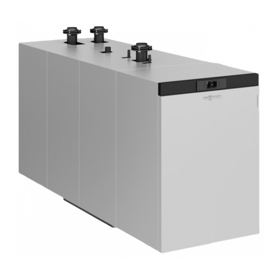
- Page 1 VIESMANN Service instructions for contractors Vitocrossal Type CRU, 800 and 1000 kW Gas condensing boiler For open flue and room sealed operation Permissible operating pressure 6 bar VITOCROSSAL Please keep safe. 5816717 GB 1/2018...
- Page 2 Hot surfaces can cause burns. Replace faulty components only with genuine ■ Before maintenance and service work, switch Viessmann spare parts. OFF the appliance and let it cool down. Never touch hot surfaces on the boiler, burner, ■ flue system or pipework.
- Page 3 For replacements, use only original spare parts supplied or approved by Viessmann. Safety instructions for operating the system If you smell gas Condensate Danger...
-
Page 4: Table Of Contents
Index Index 1. Information Symbols ....................Intended use ..................Product information ................2. Commissioning, inspec- Steps - commissioning, inspection and maintenance ......tion, maintenance 3. Burner control unit Burner control unit VUC 310 ..............32 Display and programming unit ............32 ■... -
Page 5: Information Symbols
Information Symbols The steps in connection with commissioning, inspec- Symbol Meaning tion and maintenance are found in the "Commission- Reference to other document containing ing, inspection and maintenance" section and identified further information as follows: Step in a diagram: Symbol Meaning The numbers correspond to the order in Steps required during commissioning... -
Page 6: Product Information
Information Product information Vitocrossal, type CRU ■ Gas condensing boiler, 800 and 1000 kW rated heat- ing output with modulating MatriX-Disk burner for natural gas E and LPG P ■ Permissible operating pressure 6 bar/0.6 MPa. -
Page 7: Commissioning, Inspec-Steps - Commissioning, Inspection And Maintenance
Commissioning, inspection, maintenance Steps - commissioning, inspection and maintenance Commissioning steps Inspection steps Maintenance steps Page • 1. Filling the heating system with water and venting............• 2. Filling the trap with water....................• • • 3. Commissioning the system....................•... - Page 8 Commissioning, inspection, maintenance Steps - commissioning, inspection and… (cont.) Commissioning steps Inspection steps Maintenance steps Page • • • 39. Checking the thermal insulation for firm seating • • • 40. Checking the installation room ventilation air apertures..........31 • 41.
-
Page 9: Filling The Heating System With Water And Venting
Commissioning, inspection, maintenance Filling the heating system with water and venting Record the volume filled, water hardness and pH value Note on page 61. Observe the "Water quality requirements" on page 59. Filling the trap with water 1. Undo the trap and fill it with water. There is a risk of flue gas escaping if it is not filled with water prior to commissioning. -
Page 10: Checking The Flue Gas Damper
Commissioning, inspection, maintenance Commissioning the system (cont.) 03. Check control cables: 08. Check the function of the neutralising system. ■ Connection and kink-free routing ■ Application and seating of retaining clips Neutralising system operating instructions 04. Check the gas supply pressure. See page 15. 09. -
Page 11: Opening The Boiler
Commissioning, inspection, maintenance Opening the boiler Fig. 2 1. Tilt the front panel at the top. Unscrew the screws 3. Undo the bottom screws on the rail extension on until the front panel can be removed. both sides. 2. Pivot up the top panel. 4. -
Page 12: Conversion To Natural Gas E
Commissioning, inspection, maintenance Conversion to natural gas E Fig. 3 1. Natural gas E with Wobbe index Ws < 2. Start the burner. 13.5 kWh/m (0 °C; 1013.25 mbar) 3. Measure the CO content in the flue gas and ■ Turn adjusting screw on the main volume but- terfly of the gas train fully towards "+". -
Page 13: Conversion To Lpg P
Commissioning, inspection, maintenance Conversion to LPG P Fig. 4 1. Turn adjusting screw on the main volume but- 4. Start the burner. terfly of the gas train fully towards " ." Turn back 4 – turns towards "+". 5. Measure the CO content in the flue gas and adjust. -
Page 14: Reducing The Heating Output (If Required)
Commissioning, inspection, maintenance Conversion to LPG P (cont.) Replacing the coding card on the burner control unit 1. Remove the CAN bus plug 2. Undo 2 fixing screws. Torque when installing: 1 Nm 3. Lift the display and programming unit and discon- nect the plug of the burner control unit connecting cable. -
Page 15: Checking The Static Pressure And Supply Pressure
Commissioning, inspection, maintenance Reducing the heating output (if required) (cont.) 8. Press R. The system will be restarted. Checking the static pressure and supply pressure Static pressure Fig. 7 Test connector 1. Close the gas shut-off valve. 4. Open the gas shut-off valve. 2. -
Page 16: Checking The Co 2 Content
Commissioning, inspection, maintenance Checking the static pressure and supply pressure (cont.) 2. Check the supply (flow) pressure. 3. Record the actual value in the report (on page 62). Set supply pressure (flow pressure): ■ Natural gas 18 to 25 mbar (1.8 to 2.5 kPa) 4. - Page 17 Commissioning, inspection, maintenance Checking the CO content (cont.) 3. Hold down S and simultaneously for longer than 2 s. The display will then show the following: ■ Status: "P" (= controlled stop) ■ Service: Modulation level in %. Here "100" = 100 % = upper heating output. "0"...
- Page 18 Commissioning, inspection, maintenance Checking the CO content (cont.) 3. Check control cables: 5. Enter actual value into the report in the appendix. ■ Connection and kink-free routing ■ Application and seating of retaining clips 4. If the CO content needs adjusting: Turn adjusting screw in small increments.
-
Page 19: Checking The Co Content
Commissioning, inspection, maintenance Checking the CO content (cont.) 5. Check the CO content at the upper and lower 6. Hold down S and simultaneously for longer than 2 s. Burner switches to operating mode. heating output again. If the CO content is not within the specified range: Repeat steps for upper and lower heating output. -
Page 20: Cleaning The Combustion Chamber And Heating Surfaces
Commissioning, inspection, maintenance Opening the combustion chamber (cont.) 2. Detach the electrical cables from the burner control 4. Undo 6 screws on the burner door. Pivot open the unit. burner door together with the burner. ■ Flue gas damper cable a¢Ö... -
Page 21: Checking All Connections And The Sensor Well On The Heating Water Side For Tightness
Commissioning, inspection, maintenance Checking all connections and the sensor well on the heating water side for tightness Overview of connections Note Check the connection for the sensor well and the mini- mum pressure switch (low water indicator) for tight- ness. Fig. -
Page 22: Checking The Condensate Drain And Neutralising System (If Installed)
The water must flow from the condensate drain Neutralising system operating instructions pipe without backing up. If necessary, clean the condensate drain pipe Note again. Neutralising medium from Viessmann Werke GmbH & Co. KG, part no. 9521702. 3. Check entire condensate drain pipe for leaks. -
Page 23: Opening The Burner Door
Commissioning, inspection, maintenance Opening the burner door Fig. 13... -
Page 24: Checking The Burner Gauze Assembly
Commissioning, inspection, maintenance Opening the burner door (cont.) Danger Risk of injury due to falling burner. Secure the burner door against unintentional closure. Checking the burner gauze assembly 1. Check burner gauze assembly and thermal insulation block for damage. 2. If a component is visibly damaged, replace the component. -
Page 25: Cleaning The Burner
Commissioning, inspection, maintenance Checking the ignition electrodes and ionisation… (cont.) Check the ignition electrodes and ionisation electrode for the correct gap to the burner gauze assembly and for possible damage. Replace the electrodes if required. Installation instructions Replacing burner components Cleaning the burner Fig. -
Page 26: Fitting The Burner
Commissioning, inspection, maintenance Cleaning the burner (cont.) 1. Undo the gas connection. 5. Undo 10 nuts. Remove the fitting. Detach the intake extension. 6. Clean the fitting and swirl plate carefully with com- 2. Remove all connecting cables at the burner control pressed air. - Page 27 Commissioning, inspection, maintenance Closing the burner door (cont.) 2. Tighten the burner door screws diagonally to a tor- 3. Check flue gas tightness again. que of 40 Nm. Danger Leaks from the burner door can result in poi- soning through escaping gas. Check the burner door for flue gas tightness, e.g.
-
Page 28: Checking The Gas Train Valves For Tightness
Commissioning, inspection, maintenance Checking the gas train valves for tightness Fig. 20 1. Close the gas shut-off valve. 6. After completing the test, close the screw on test connector . Check the test connector for leaks. 2. Undo the screw in test connector , but do not remove. -
Page 29: Checking The Filter Element In The Gas Line
Commissioning, inspection, maintenance Checking the gas train filter element (cont.) 4. Check for gas tightness. Danger Escaping gas leads to a risk of explosion. Check the gas train for gas tightness. Please note The use of leak detection spray can result in faulty operation. -
Page 30: Closing The Boiler Casing
Commissioning, inspection, maintenance Closing the boiler casing Close the boiler again in reverse order to Fig. 2 on page 11. Checking the gaskets on the flue gas side 1. Check the joints between flue gas collector boiler back panel for tightness. Note Check the gaskets at full load operation, for exam- ple using an inspection mirror, gas sensor or ther-... -
Page 31: Checking The Mixer For Ease Of Operation And Leaks
Commissioning, inspection, maintenance Checking the expansion vessel (cont.) 2. If the expansion vessel pre-charge pressure is 3. Top up with water. The charge pressure of the lower than the static system pressure, top up with cooled system must be 0.1 to 0.2 bar (10 to nitrogen. -
Page 32: Burner Control Unit Burner Control Unit Vuc 310
Burner control unit Burner control unit VUC 310 Display and programming unit A display and programming unit is integrated into the Note burner control unit. The display screen shows the rele- Depending on the system configuration, the display vant operating status, the service and parameter sta- and control functions can in part also be carried out on tus, as well as any fault or error messages. -
Page 33: Info Display/Configuration Display
Burner control unit Burner control unit VUC 310 (cont.) Display Meaning Status Service Fig. 23 Example Status Service Operation with flame After flame post-purge Dwell program, no air pressure Dwell program, no gas pressure or mains undervoltage Forced ventilation if no flame formation has been detected. Safety shutdown due to flame tear-off Info display/configuration display The information display and the configuration display... - Page 34 Burner control unit Burner control unit VUC 310 (cont.) Configurations: Menu Description point Changeover from the operating display of the burner control unit phase to other proc- ess information Configuration of control function operating parameters Menu point "5" is used to display the following process information: Sub-menu point Process information Unit/scale...
-
Page 35: Resetting Operating Parameters To Their Delivered Condition
Burner control unit Burner control unit VUC 310 (cont.) Sub-menu Parameter Setting range/unit Delivered condition point Boiler controller start hysteresis (effec- 0 to 20 K tive during minimum pause) Boiler controller stop hysteresis (effec- 0 to 20 K tive during minimum pause) Reset all operating parameters to their delivered condition. -
Page 36: Flow Diagram
Burner control unit Flow diagram Fig. 24... -
Page 37: Description Of State
Burner control unit Flow diagram (cont.) Description of state: Phase Display Description Duration System start "A" System start 10 s Fan ramp-up, system start max. 20 s Forced ventilation, system start 20 s Relay test "P" Fan ramp-up for test max. -
Page 38: Troubleshooting Fault Display
Troubleshooting Fault display If the burner control unit switches to a fault state, the Fault code of the most recent fault, see table from fault display is automatically activated. The most page. recent fault is then displayed. The fault LED is also illu- minated in the case of a non-lockout fault, or flashes 1. - Page 39 Troubleshooting Fault codes (cont.) Displayed fault System characteristics Cause Measures code F B7 Burner control unit in a fault Coding card not inserted Insert coding card. Check coding state; system cooling down; in the burner control unit; card. Replace if necessary. burner control unit locked out.
- Page 40 Troubleshooting Fault codes (cont.) Displayed fault System characteristics Cause Measures code F F4 Flame does not build during Incorrect gas type selec- Adjust gas type (see page 10). the safety time, no signal re- ported by the ionisation flame monitor. F F4 Flame does not build during Gas train does not open.
- Page 41 Troubleshooting Fault codes (cont.) Displayed fault System characteristics Cause Measures code F F9 No feedback from fan External fan power supply Check cable" A" and external a-Ö not connected, faulty or power supply. Replace cable or defective. If voltage is fan.
-
Page 42: Internal System Faults
Troubleshooting Fault codes (cont.) Displayed fault System characteristics Cause Measures code F F1 Burner control unit in a fault Flue gas temperature lim- Wait until temperature falls below ■ state; system cools down. iter has responded the permissible flue gas tempera- Flue gas temperature ture. -
Page 43: Faults Without Fault Display
Troubleshooting Fault codes (cont.) Detailed er- Component/signal Cause of fault Measure ror code Plug 41 demand T2 High switching se- Check whether external voltage present. quence, switch flutters Check on-site connection. External voltage Plug 90 T8 High switching se- Check whether external voltage present. quence, switch flutters Check on-site connection. - Page 44 Troubleshooting Faults without fault display (cont.)
-
Page 45: Parts Lists Overview Of Assemblies
Parts lists Overview of assemblies The following details are required when ordering parts: ■ Serial no. (see type plate ■ Assembly (from this parts list) Position number of the individual part within the ■ assembly (from this parts list) 0004 0003 0001 0002... -
Page 46: Boiler Assembly
Parts lists Boiler assembly 0001 0001 0004 0005 0002 0007 0006 0003 0001 0005 0008 Fig. 27... - Page 47 Parts lists Boiler assembly (cont.) Pos. Part 0001 Gasket DN 100 PN 6 0002 Sensor well with clip 0003 Packing cord 0004 Gasket set 0005 Sealant 0006 Flue gas collector with gasket 0007 Flue system collar 0008 Stench trap...
-
Page 48: Casing Assembly
Parts lists Casing assembly 0029 0011 0009 0030 0031 0032 0033 0013 0014 0013 0013 0012 0008 0013 0034 0007 0010 0006 0005 0008 0021 0020 0007 0035 0006 0022 0005 0003 0004 0036 0017 0037 0019 0015 0025 0024 0028 0026 0001... - Page 49 0030 Top panel, left 0031 Top panel, right 0032 Top panel, centre 0033 Top panel, back 0034 Back panel, top 0035 Control unit cover 0036 Back panel, centre 0037 Back panel, bottom 0038 Viessmann logo 0039 Vitocrossal logo 0040 Fixings...
-
Page 50: Matrix-Disk Burner Assembly
Parts lists MatriX-Disk burner assembly 0020 0021 0017 0006 0007 0002 0013 0016 0014 0008 0011 0018 ---0016 0015 0004 0012 0005 0008 0010 0015 0010 0003 0009 0001 0019 Fig. 29... - Page 51 Parts lists MatriX-Disk burner assembly (cont.) Pos. Part 0001 Matrix-Disk burner 0002 Burner control unit and cables 0003 0004 Gas train 0005 Mixer unit 0006 Gas pressure switch 0007 Gas pressure switch 0008 Supply air collector 0009 Gasket, gas fan 0010 O-ring gasket 0011...
-
Page 52: Burner Control Unit Assembly
Parts lists Burner control unit assembly 0001 0002 0003 0004 0005 0006 0009 0010 0011 0012 0013 0018 0014 0015 0016 0017 0019 Fig. 30... - Page 53 Parts lists Burner control unit assembly (cont.) Pos. Part 0001 Burner control unit VUC310-C01.005 0002 Programming unit 0003 Connecting cable, 38 bypass 0004 Ionisation cable 11/auxiliary earth 0005 Ignition transformer connecting cable 54 0006 Gas train connecting cable 0009 Air pressure switch with connecting cable 131 0010 Air pressure switch with connecting cable 131A 0011...
-
Page 54: Control Unit Assembly
Parts lists Control unit assembly 0003 0001 0002 0003 0008 0004 0003 0002 0006 0007 0013 0010 0011 0017 0009 0016 0014 0019 0012 0018 Fig. 31... - Page 55 Parts lists Control unit assembly (cont.) Pos. Part 0001 Programming module 0002 Toggle switch OFF 2-pole 0003 Slider, left and right 0004 Vitotronic programming unit 0006 Cable with 2 angle connectors 0007 LAN cable 0008 Vitocrossal terminal box 0009 Coding card 0010 Cover, cable entry (2 pce) 0011...
-
Page 56: Component Overview Overview Of Burner Components
Component overview Overview of burner components Fig. 32 Display and programming unit Supply air collector Burner control unit Thermal insulation block Burner door Ignition electrodes Gas train Burner gauze assembly, MatriX-Disk Gas pressure switch Ionisation electrode Gas pressure switch 2 Ignition unit Gas supply pipe Air pressure switch LDW2... -
Page 57: Function Description Air Pressure Switch
Function description Air pressure switch Fan pressure monitoring function (LDW1) The switching threshold of air pressure switch 1 (plug The fault shutdown is indicated by fault codes "F F5" and "F F7" on the burner control unit display (see ) is monitored in all fan ramp-up phases and checked during modulating burner operation. -
Page 58: Connection Diagrams Burner Control Unit Connection Diagram
Connection diagrams Burner control unit connection diagram Fig. 34 Burner control unit VUC 310 Air pressure switch 1 Flame monitor (ionisation current) Gas pressure switch GDW1 Vitotronic control unit Air pressure switch 2 Servomotor for rotary damper or 2/2-way solenoid Flue gas temperature sensor 1 valve Flue gas temperature sensor 2... - Page 59 Water quality requirements Water quality requirements Note Prevention of damage due to scaling Observing the following requirements is necessary to safeguard your warranty rights. Prevent excessive scale build-up (calcium carbonate) The warranty excludes damage due to corrosion and on the heating surfaces. For heating systems with scaling.
- Page 60 Water quality requirements (cont.) Failure to observe the requirements of VDI Guideline Correctly sized sealed unvented systems operating at 2035 can result in damaging limescale deposits. In the correct pressure, e.g. systems with expansion ves- such cases, the service life of the installed boilers will, sel, offer good protection against the ingress of air- most often, already have been reduced.
-
Page 61: Reports
Reports Reports Fill water report Fill water Top-up water Meter reading Total water volume Date — — — — — — — — — — — — — — — — — — — Max. fill volume: ......m Water quality report Total hardness pH value Water treatment... - Page 62 Reports Reports (cont.) Settings and measurement values Commissioning Maintenance/Service Static pressure mbar Supply pressure (flow pressure) for natural gas E mbar for LPG P mbar Tick gas type. Carbon dioxide content CO At upper rated heating actual % by vol. ■...
-
Page 63: Specification
Specification Specification Vitocrossal boiler Rated heating output : TF/TR = 80/60 121 to 727 152 to 909 : TF/TR = 50/30 133 to 800 167 to 1000 cond Rated heat input 127 to 762 159 to 953 Boiler product ID CE-0085CS0411 Permiss. - Page 64 Specification Specification (cont.) Rated heating output : TF/TR = 80/60 121 to 727 152 to 909 : TF/TR = 50/30 133 to 800 167 to 1000 cond Gas flow rate, natural gas E at 15 °C; 1.013 bar At rated heating output 80.6 100.8 ■...
-
Page 65: Final Decommissioning Final Decommissioning And Disposal
Final decommissioning Final decommissioning and disposal Viessmann products can be recycled. Components For decommissioning the system, isolate the system and substances from the system are not part of ordi- from the power supply and allow components to cool nary household waste. -
Page 66: Certificates Eu Declaration Of Conformity
EU Declaration of Conformity Vitocrossal MatriX-Disk burner, type CRU, 800 to 1000 kW We, Viessmann Werke GmbH & Co. KG, D-35107 Allendorf, declare as sole responsible body that the named product complies with the provisions of the following directives and regulations. -
Page 67: Manufacturer's Certificate According To The 1St German Immissions Order (Bimschv)
Head of Strategic Quality Management Manufacturer’s certificate according to the 1st German Immissions Order (BImSchV) We, Viessmann Werke GmbH & Co. KG, D-35107 Allendorf, confirm that the product Vitocrossal, type CRU complies with the following conditions stipulated by the 1st German Immissions Order (BImSchV): ■... -
Page 68: Keyword Index
Keyword index Keyword index Air pressure switch.............57 Heating surfaces, cleaning.........20 Heating system – Filling with water............9 Boiler door – Opening..............11 Boiler water requirements.......... 59 Ignition electrodes, checking........24 Burner Instructing the system user........31 – Cleaning..............25 Intended use..............5 – Fitting..............26 Internal system faults.......... - Page 72 Viessmann Werke GmbH & Co. KG Viessmann Limited D-35107 Allendorf Hortonwood 30, Telford Telephone: +49 6452 70-0 Shropshire, TF1 7YP, GB Fax: +49 6452 70-2780 Telephone: +44 1952 675000 www.viessmann.com Fax: +44 1952 675040 E-mail: info-uk@viessmann.com...
Need help?
Do you have a question about the VITOCROSSAL CRU 800 kW and is the answer not in the manual?
Questions and answers