Viessmann Vitocrossal 300 Installation Instructions For Contractors
Hide thumbs
Also See for Vitocrossal 300:
- Service instructions manual (164 pages) ,
- Service instructions for contractors (148 pages) ,
- Service manual (108 pages)

Related Manuals for Viessmann Vitocrossal 300


Summary of Contents for Viessmann Vitocrossal 300
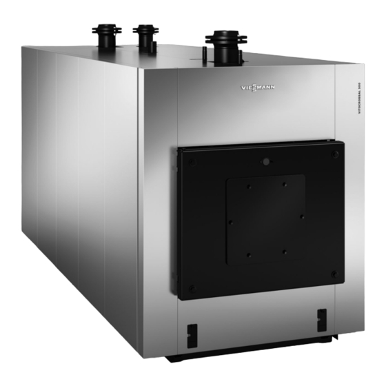
- Page 1 VIESMANN Installation instructions for contractors Vitocrossal 300 Type CR3B, 787 to 1400 kW Gas condensing boiler VITOCROSSAL 300 Dispose after installation. 5836848 GB 6/2019...
- Page 2 Safety instructions Please follow these safety instructions closely to prevent accidents and material losses. Safety instructions explained Danger Note This symbol warns against the risk of injury. Details identified by the word "Note" contain additional information. Please note This symbol warns against the risk of material losses and environmental pollution.
-
Page 3: Table Of Contents
Index Information Disposal of packaging ................Symbols ....................Intended use ..................Product information ................System examples ................■ Preparing for installation Clearances and dimensions ..............Anti-vibration boiler support ..............■ Thermal insulation sections ..............Thermal insulation, pack 1 ..............■ Thermal insulation, pack 2 .............. -
Page 4: Information Disposal Of Packaging
Disposal of packaging Please dispose of packaging waste in line with statu- tory regulations. Symbols Symbol Meaning Reference to other document containing further information Step in a diagram: The numbers correspond to the order in which the steps are carried out. Warning of material losses and environ- mental pollution Live electrical area... -
Page 5: Product Information
Product information Vitocrossal 300, type CR3B ■ Fuel: Natural gas E, natural gas LL and LPG Rated heating output 787 kW and 1400 kW ■ Permissible operating pressure 6 bar (0.6 MPa) ■ System examples Available system examples: See www.viessmann-... -
Page 6: Preparing For Installation Clearances And Dimensions
Clearances and dimensions Note The stated clearances are recommended clearances. Minimum clearances are indicated in brackets. 200 (100) 1600 (300) Fig. 1 Boiler Burner Anti-vibration boiler supports Note In the delivered condition, the burner door opens to the right. The hinge pins of the burner door can be reposi- tioned so that the burner door opens to the left. -
Page 7: Anti-Vibration Boiler Support
Clearances and dimensions (cont.) Anti-vibration boiler support Fig. 2 Rated heating output 1100 1400 Permissible load 4668 6004 Boiler front Length ■ Quantity ■ Boiler back Length ■ Quantity ■ Spring element, unloaded ■ Spring element, loaded 38-39 ■... -
Page 8: Thermal Insulation Sections
Thermal insulation sections The thermal insulation and casing are supplied in 3 Note packs. The following is a list of the components in the The position numbers correspond to the "Casing individual packs. assembly" parts list in the service instructions. Thermal insulation, pack 1 0009 0015... -
Page 9: Thermal Insulation, Pack 2
Thermal insulation sections (cont.) Thermal insulation, pack 2 0017 0024 0025 0018 0024 0040 0023 0019 0015 0020 Fig. 4 Pos. Designation Pos. Designation 0015 Side panel, centre 0023 Back panel, bottom 0017 Side panel, back left 0024 Cover panel 0018 Side panel, front left 0025... -
Page 10: Thermal Insulation, Pack 3
Thermal insulation sections (cont.) Thermal insulation, pack 3 0027 0028 0004 0030 0026 0012 0003 0010 0029 0010 0010 0031 0010 0002 0041 0001 0008 0006 0036 0007 0037 0005 0038 0043 Fig. 5 Pos. Designation Pos. Designation 0001 Rail, top front right 0027 Top panel, back 0002... -
Page 11: Fixings
Thermal insulation sections (cont.) Fixings The following is a list of the components required for fastening the individual items. For easier identification, the components have been assigned position num- bers. The position numbers in circles are referenced in the descriptions of the steps to be carried out. Pos. -
Page 12: Installation Sequence Siting The Boiler
Siting the boiler Installation without anti-vibration boiler supports Fig. 6 1. Insert the adjusting screws into the base rails. 2. Level the boiler horizontally. No special founda- Position a plate, e.g. a flat steel strip, underneath tions are required. the adjusting screws to distribute the load evenly. Installation with anti-vibration boiler supports To ensure that the spring elements are uniformly loa- 4. -
Page 13: Assembling The Boiler
Assembling the boiler 150 Nm M 16 60 Nm Fig. 7 Combustion chamber module Guide bolts for combustion chamber module with Heat exchanger module M 16 nuts and dished washers (supplied) Gaskets (part of the standard delivery) Packing cord 1. Lift the heat exchanger module by the lifting eye. Please note Scratches inside the combustion chamber or on 5. -
Page 14: Fitting The Supplied Foot Supports To The Heat Exchanger Module
Assembling the boiler (cont.) Fitting the supplied foot supports to the heat exchanger module Fig. 8... -
Page 15: Levelling The Combustion Chamber And Heat Exchanger Modules Horizontally
Assembling the boiler (cont.) Levelling the combustion chamber and heat exchanger modules horizontally Fig. 9... -
Page 16: Connections On The Heating Water Side
Connections on the heating water side Note The boiler is only suitable for fully pumped hot water heating systems. Fig. 10 Boiler return 2: PN 6 DN 100 Boiler flow Boiler return 1 787 and 978 kW: PN 6 DN 100 787 and 978 kW: PN 6 DN 100 1100 and 1400 kW: PN 6 DN 125... -
Page 17: Fitting The Thermal Insulation
Connections on the heating water side (cont.) 2. Connect the hydraulic lines. 3. Seal any unused connections. System with 1 heating circuit Note Connect the heating return to boiler return 1 Do not connect any heat consumers to the connec- ■... -
Page 18: Rails, Top And Bottom
Fitting the thermal insulation (cont.) Rails, top and bottom Fig. 12 Rail, front (short) Rail, back (long) 1. Insert M 6 screws halfway into the base and Note head rails. Ensure the bottom front rails are flush with the boiler floor, then align the back rails accordingly. -
Page 19: Reinforcing Struts And Tie-Bars
Fitting the thermal insulation (cont.) Reinforcing struts and tie-bars Fig. 13 1. Secure reinforcing strut with self-tapping screw 4. Check whether the tie-bars and rails form a right 4.8 x 9.5 to upper rails angle. 2. Secure 4 tie-bars with self-tapping screw 4.8 x 5. -
Page 20: Heat Exchanger Support Panel And Thermal Insulation Mat
Fitting the thermal insulation (cont.) Heat exchanger support panel and thermal insulation mat 4,8 x 9,5 1. M6 x 16 Fig. 14 Heat exchanger support panel Heat exchanger thermal insulation mat (black side outwards) Support bracket, screws (for 1100 and 1400 kW) 3. -
Page 21: Side Panels, Burner Cables And Boiler Water Temperature Sensor
Fitting the thermal insulation (cont.) Side panels, burner cables and boiler water temperature sensor lÖ Fig. 15 Burner cables lÖ KTS, boiler water temperature sensor (supplied § with the control unit) STB, sensors of high limit safety cut-out, are only fitted with the control unit. -
Page 22: Front Corner Rails
Fitting the thermal insulation (cont.) Note Start the assembly with front r.h. side panel or with back l.h. side panel Control unit side panel can be fitted as a second side panel from the front, either to the right or left. Front corner rails 2. -
Page 23: Front Panels
Fitting the thermal insulation (cont.) Front panels 2x 4,8 x 9,5 lÖ Fig. 17 Spring clips enclosed with fixings (4 per front panel). Strain relief... -
Page 24: Back Panels
Fitting the thermal insulation (cont.) Back panels 4,8 x 9,5 Fig. 18 5. Secure the cable retainer on the control unit side. -
Page 25: Top Panels
Fitting the thermal insulation (cont.) Top panels 3 x 4,8 x 9,5 Fig. 19 Slot Tabs... -
Page 26: Control Unit Installation
Control unit installation Preparing the control unit installation § 6x 4,8 x 9,5 Fig. 20 Note Install boiler water temperature sensor and the sen- § sors of the high limit safety cut-out on the boiler; see page 21. -
Page 27: Fitting And Connecting The Control Unit
Control unit installation (cont.) Fitting and connecting the control unit Fig. 21 Type plate Mounting bracket, fascia Boiler control unit installation and service 4. Remove the lower section (with barcode) from the instructions small type plate of the heat exchanger module. Attach this section to the type plate for the whole 2. -
Page 28: Mounting The Siphon
Mounting the siphon Note Undo the bottom section of the trap and fill it with water. Danger If the trap is not full, flue gas can escape. Escaping flue gas can cause life threatening carbon monoxide poisoning. Always fill the trap with water before commis- sioning. -
Page 29: Connections On The Flue Gas Side
Connections on the flue gas side Butterfly valve For some burners, it is necessary to regulate the back pressure. For this purpose, a manually adjustable but- terfly valve is installed. Flue pipe internal diameter 787 and 978 kW 302 mm 1100 and 1400 kW 352 mm 5. -
Page 30: Combustion Chamber Sight Glass
Mounting the burner (cont.) If the burner plate is not factory-fitted: Drill the burner Max. flame tube aperture: 350 mm fixing holes in the burner flange. Cut out the burner aperture with an oxy-acetylene torch. Ø = Ø B -10 Fig. -
Page 31: Closing Off The Sight Glass Aperture On Burners Without Ventilation Connection
Combustion chamber sight glass (cont.) 2. Only for burners with ventilation connection: Connect plastic hose with the sight glass and the fan part of the burner (test port for "static burner pressure"). Fig. 27 Closing off the sight glass aperture on burners without ventilation connection On burners without ventilation connection for sight glass, the sight glass aperture in the boiler door is closed off with a plug. -
Page 32: Pressure Switch
Combustion chamber sight glass (cont.) Fig. 29 Pressure switch Pressure switch The pressure switch is a safety accessory and is Note required for every boiler to EN 303 with pressure-jet The hose for measuring the pressure is also connec- burners to EN 676 (third party burners) for shutting ted to the combustion chamber sight glass. - Page 33 Closing the boiler door (cont.) Danger Leaks can result in a risk of poisoning through escaping gas. Prior to commissioning, check the boiler door gasket for correct seating and realign if neces- sary. Otherwise secondary ventilation can occur, condensate may form on the boiler door and gas can escape.
-
Page 34: Commissioning And Adjusting The Burner
Adjusting the burner For burner adjustment, see separate burner Note documentation. Do not operate the boiler beyond its rated heating out- put. Note Fully open the optional butterfly valve in the flue outlet Rated heating output Pressure drop on the when adjusting the burner. - Page 36 Viessmann Werke GmbH & Co. KG Viessmann Limited D-35107 Allendorf Hortonwood 30, Telford Telephone: +49 6452 70-0 Shropshire, TF1 7YP, GB Fax: +49 6452 70-2780 Telephone: +44 1952 675000 www.viessmann.com Fax: +44 1952 675040 E-mail: info-uk@viessmann.com...
Need help?
Do you have a question about the Vitocrossal 300 and is the answer not in the manual?
Questions and answers