Viessmann Vitocrossal 300 Service Instructions For Contractors
Gas condensing boiler with matrix cylinder burner for natural gas e and ll
Hide thumbs
Also See for Vitocrossal 300:
- Service instructions manual (164 pages) ,
- Service instructions for contractors (148 pages) ,
- Service manual (108 pages)

Related Manuals for Viessmann Vitocrossal 300


Summary of Contents for Viessmann Vitocrossal 300
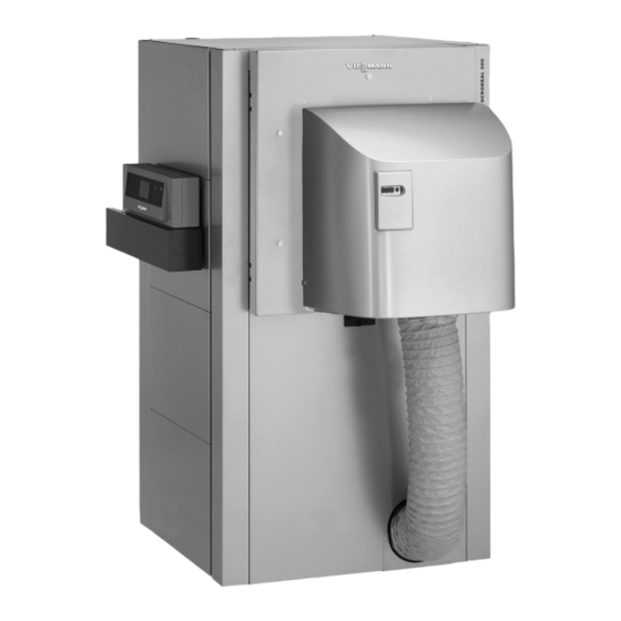
- Page 1 VIESMANN Service instructions for contractors Vitocrossal 300 Type CT3U, 400 to 630 kW Gas condensing boiler with MatriX cylinder burner for natural gas E and LL VITOCROSSAL 300 Please keep safe. 5834360 GB 1/2019...
- Page 2 Never touch hot surfaces on the boiler, burner, lidate our warranty. ■ flue system or pipework. For replacements, use only original spare parts supplied or approved by Viessmann. Please note Electronic assemblies can be damaged by elec- trostatic discharge. Prior to commencing work, touch earthed objects such as heating or water pipes to dis- charge static loads.
- Page 3 Safety instructions Safety instructions (cont.) Safety instructions for operating the system If you smell gas Flue systems and combustion air Danger Ensure that flue systems are clear and cannot be Escaping gas can lead to explosions which may sealed, for instance due to accumulation of conden- result in serious injury.
- Page 4 Index Index 1. Information Symbols ....................Intended use ..................Product information ................System examples ................■ Burner ....................2. Commissioning, inspec- Steps - commissioning, inspection and maintenance ......tion, maintenance 3. Control unit Setting the codes at the control unit ............19 4.
- Page 5 Information Symbols The steps in connection with commissioning, inspec- Symbol Meaning tion and maintenance are found in the "Commission- Reference to other document containing ing, inspection and maintenance" section and identified further information as follows: Step in a diagram: Symbol Meaning The numbers correspond to the order in Steps required during commissioning...
- Page 6 Information Product information Vitocrossal 300, type CT3U ■ Gas condensing boiler – Rated heating output 400 to 630 kW – For MatriX cylinder burner for natural gas E and LL Permissible operating pressure 5.5 bar ■ System examples Available system examples: See www.viessmann- schemes.com.
-
Page 7: Table Of Contents
Commissioning, inspection, maintenance Steps - commissioning, inspection and maintenance Commissioning steps Inspection steps Maintenance steps Page • • • 1. Note on initial commissioning, inspection and maintenance........• 2. Checking the high limit safety cut-out setting..............• 3. Filling the heating system with water and venting............•... -
Page 8: Note On Initial Commissioning, Inspection And Maintenance
Commissioning, inspection, maintenance Note on initial commissioning, inspection and maintenance Product contains ceramic fibres Danger When working with high temperature insulating materials that contain zirconium or aluminium silicate ceramic fibres, fibre dust may develop. This fibre dust can be harmful to health. -
Page 9: Filling The Trap With Water
Commissioning, inspection, maintenance Filling the trap with water Fig. 2 1. Remove lower back panel 4. Refit the siphon. . To do so, undo the 4 quarter-turn rotary latches Danger 2. Undo the siphon and fill with water, otherwise flue Flue gas escaping from the trap can cause gas may escape. -
Page 10: Commissioning The System
Commissioning, inspection, maintenance Commissioning the system Burner service instructions 07. Adjust the codes on the boiler control unit in ■ ■ Vitotronic operating instructions and service accordance with the table on page 19. instructions ■ Neutralising system operating instructions Vitotronic installation and service instruc- tions 01. -
Page 11: Opening The Boiler Door
Commissioning, inspection, maintenance Opening the boiler door Danger When working with high temperature insulating materials that contain zirconium or aluminium silicate ceramic fibres, fibre dust may develop. This fibre dust can be harmful to health. Only trained personnel may adjust or replace the insulation. -
Page 12: Separating The Neutralising System, Connecting The Drain Hose
Commissioning, inspection, maintenance Opening the boiler door (cont.) Opening the boiler door Fig. 5 Please note Scratches inside the combustion chamber can lead to corrosion. Never place tools or other objects inside the combustion chamber. Separating the neutralising system, connecting the drain hose Fig. -
Page 13: Cleaning The Combustion Chamber And Heating Surfaces
Commissioning, inspection, maintenance Separating the neutralising system, connecting… (cont.) 5. Remove drain hose 7. Fill trap . Clean condensate with water (see page 9). drain on the inside using a plastic brush. 6. Connect siphon and hose Cleaning the combustion chamber and heating surfaces Thoroughly clean the combustion chamber and heat- ing surfaces with a water jet. -
Page 14: Cleaning And Reconnecting The Condensate Drain Pipe
Commissioning, inspection, maintenance Cleaning and reconnecting the condensate drain pipe Note Clean the inside of the condensate drain pipe at least once a year. Fig. 7 1. Disconnect drain hose 4. Undo and flush lower part of siphon 2. Clean the inside of the condensate drain pipe 5. -
Page 15: Checking All Connections On The Heating Water Side For Leaks
Commissioning, inspection, maintenance Checking all connections on the heating water side for leaks Danger Note There is a risk of injury when working on pres- Also check the connections for the control equipment surised components. and the minimum pressure switch (low water indicator) The connections on the heating water side must for tightness. -
Page 16: Checking The Water Quality
Commissioning, inspection, maintenance Checking gas connections for tightness (cont.) 2. Open the gas shut-off valve. 4. Start the burner (see page 10). 3. Check the joints in the gas train for leaks using a gas leak detector. Please note The use of leak detection spray can result in faulty operation. -
Page 17: Checking The Gaskets On The Flue Gas Side
Commissioning, inspection, maintenance Checking the gaskets on the flue gas side 1. Check the flue gas collector seals for tightness. Danger Escaping flue gas poses a risk to health. Check gaskets on the flue gas collector and adjust if required. Note Check the gaskets at full load operation, for exam- ple using an inspection mirror, dew point indicator... - Page 18 Commissioning, inspection, maintenance Instructing the system user (cont.) Operating and service documents 1. Complete and detach the customer registration 2. File all parts lists, operating and service instruc- card: tions in the folder and hand this over to the system ■...
- Page 19 Control unit Setting the codes at the control unit Vitotronic service instructions In conjunction with the following control units: ■ Vitotronic 100, type CC1E ■ Vitotronic 200, type CO1E Vitotronic 300, type CM1E ■ Parameter Rated heating output of the MatriX cylinder burner in kW Coding card Boiler group 1042...
- Page 20 Functions Air pressure switch Fan pressure monitoring (LDW1) The air pressure switch triggers a fault shutdown of the burner control unit under the following circumstances: ■ If the static pressure check was unsuccessful after approx. 5 minutes ■ If the air pressure is outside the permiss. range in the pre-purge phase (tolerance time approx.
- Page 21 Functions Air pressure switch (cont.) Combustion chamber pressure monitoring (LDW2) To monitor the combustion chamber pressure, the switching threshold of air pressure switch 2 (LDW2) is monitored in all operating phases (except during the safety and stabilising time). The air pressure switch triggers a fault shutdown of the burner control unit under the following circumstances: If the combustion chamber pressure is outside the ■...
- Page 22 Functions Air pressure switch (cont.)
- Page 23 Parts lists Overview of assemblies The following details are required when ordering parts: ■ Serial no. (see type plate ■ Assembly (from this parts list) Position number of the individual part within the ■ assembly (from this parts list) Fig. 12 Type plate Thermal insulation assembly Boiler assembly...
- Page 24 Parts lists Boiler assembly 0008 0003 0006 0005 0003 0009 0008 0010 0002 0003 0005 0006 0007 0011 0011 0012 0005 0010 0001 0004 Fig. 13...
- Page 25 Thermal insulation block and mat for boiler door 0004 Stench trap 0005 Mounting bracket 0006 Packing GF 20 x 15 x 2040 0007 Bolt 0008 Gasket DN 100 0009 Gasket DN 80 0010 Viessmann logo 0011 Door panel (with pos. 0010) 0012 Flue gas temperature sensor...
- Page 26 Parts lists Boiler assembly (cont.) Cable set assembly 0001 0002 0003 0004 0005 0006 Fig. 14...
- Page 27 Parts lists Boiler assembly (cont.) 0001 Dual temperature sensor 0002 Burner cable 41 0003 Cable KM-BUS 145 0004 Power cable 40 0005 Cable 40/156 0006 Flue gas temperature sensor connecting cable 15A/15B...
- Page 28 Parts lists Thermal insulation assembly 0012 0010 0011 0029 0017 0015 0013 0018 0007 0005 0009 0036 0030 0016 0019 0033 0032 0037 0031 0002 0007 0022 0008 0024 0023 0027 0027 0001 0004 0025 0028 0033 0003 0014 0021 0034 0026 0006...
- Page 29 Front panel, top 0030 Back panel, adaptor 0031 Back panel, flue gas collector, left 0032 Back panel, flue gas collector, right 0033 Sealing clip 0034 Quarter-turn rotary latch with toggle 0035 Damping washer 0036 Vitocrossal 300 logo 0037 Reinforcement, flue gas collector...
- Page 30 Parts lists Parts not shown 0003 Fixings 0004 Decorative strip 0005 Touch-up spray paint, Vitosilver 0006 Touch-up paint stick, Vitosilver 0007 Installation instructions 0008 Service instructions...
- Page 31 Water quality requirements Water quality requirements Note Observation of the following requirements is a neces- sary condition for safeguarding your warranty rights. The warranty excludes damage due to corrosion and scaling. Prevention of damage due to scaling Prevent excessive scale build-up (calcium carbonate) on the heating surfaces.
- Page 32 Water quality requirements Water quality requirements (cont.) Any limescale deposits that have formed because of a This measure must be carried out by a qualified con- failure to observe the requirements of guideline tractor. Inspect the heating system for possible dam- VDI 2035 will in most cases already have caused a age prior to returning it into use.
- Page 33 Reports Water quality Meter reading Fill and top-up water Total water volume Total hardness pH value Date Feedwater Boiler water...
- Page 34 Specification Specification Rated heating output = 50/30 °C 135 to 400 168 to 500 209 to 630 cond = 80/60 °C 123 to 370 153 to 460 192 to 575 Rated heat input 127 to 381 158 to 474 198 to 593 Product ID CE-0085AQ0257 Permiss.
- Page 35 Final decommissioning and disposal Final decommissioning and disposal Viessmann products can be recycled. Components For decommissioning the system, isolate the system and substances from the system are not part of ordi- from the power supply and allow components to cool nary household waste.
- Page 36 Manufacturer's certificate We, Viessmann Werke GmbH & Co. KG, D-35107 Allendorf, confirm that the product Vitocrossal 300, type CT3U, complies with the following conditions stipulated by the 1st German Immissions Order (BImSchV): ■ limits according to paragraph 6 (1).
- Page 37 Keyword index Keyword index Air pressure switch Manufacturer's certificate........... 36 – Combustion chamber pressure monitoring (LDW2)21 – Fan pressure monitoring (LDW1)......20 Assembly Neutralising system..........12, 14 – Boiler............... 24 Note on maintenance........... 8 – Cable set..............26 – Overview..............23 – Thermal insulation...........28 Operating and service documents......
- Page 40 Viessmann Werke GmbH & Co. KG Viessmann Limited D-35107 Allendorf Hortonwood 30, Telford Telephone: +49 6452 70-0 Shropshire, TF1 7YP, GB Fax: +49 6452 70-2780 Telephone: +44 1952 675000 www.viessmann.com Fax: +44 1952 675040 E-mail: info-uk@viessmann.com...
Need help?
Do you have a question about the Vitocrossal 300 and is the answer not in the manual?
Questions and answers