Viessmann Vitocrossal 300 Installation Instructions For Contractors
Hide thumbs
Also See for Vitocrossal 300:
- Service instructions manual (164 pages) ,
- Service instructions for contractors (148 pages) ,
- Service manual (108 pages)

Related Manuals for Viessmann Vitocrossal 300


Summary of Contents for Viessmann Vitocrossal 300
- Page 1 VIESMANN Installation instructions for contractors Vitocrossal 300 Type CT3B, 187 to 635 kW Gas condensing boiler VITOCROSSAL 300 Dispose after installation. 5800301 GB 9/2018...
- Page 2 Safety instructions Please follow these safety instructions closely to prevent accidents and material losses. Safety instructions explained Danger Note This symbol warns against the risk of injury. Details identified by the word "Note" contain additional information. Please note This symbol warns against the risk of material losses and environmental pollution.
-
Page 3: Table Of Contents
Index Information Disposal of packaging ................Symbols ....................Intended use ..................Product information ................System examples .................. Preparing for installation Clearance dimensions ................Installation sequence Siting and levelling the boiler ..............Converting the boiler door opening ............10 Assembly after dismantling ..............10 Connections on the heating water side .......... -
Page 4: Information Disposal Of Packaging
Please dispose of packaging waste in line with statu- DE: Use the disposal system organised by tory regulations. Viessmann. AT: Use the ARA statutory disposal system (Altstoff Recycling Austria AG, licence number 5766). CH: Packaging waste is disposed of by the HVAC contractor. -
Page 5: Product Information
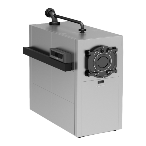
Intended use also includes the adherence to mainte- nance and inspection intervals. Product information Vitocrossal 300, type CT3B ■ Fuel: Natural gas E and natural gas LL Rated heating output 187 to 635 kW ■... -
Page 6: Preparing For Installation Clearance Dimensions
Clearance dimensions Note The hinge pins can be repositioned so that the boiler door opens to the left. Dimensions in brackets are minimum clearances. 500 (400) 500 (50) (400) Fig. 1 Boiler Burner Adjustable anti-vibration feet Anti-vibration boiler supports Fig. 4 Fig. - Page 7 Clearance dimensions (cont.) Rated heating output 1000 1100 1500 1500 1500 Observe the installed burner length Adjustable anti-vibration boiler feet Permissible load 1200 Number Anti-vibration boiler supports Permissible load 1200 1500 1750 c (front) / number mm/pce 125/2 375/2 500/2 c (back) / number mm/pce 125/2...
-
Page 8: Installation Sequence Siting And Levelling The Boiler
Siting and levelling the boiler Note Lifting eyes are welded to the top of the boiler for attaching the lifting gear. Alternatively, use the speci- fied holes in the boiler floor. Fig. 5 Lifting gear attachment points: Lifting the complete appliance Lifting the combustion chamber module Lifting the heat exchanger module Note... - Page 9 Siting and levelling the boiler (cont.) Fig. 6 1. Insert adjusting screws (inside the bag on the Adjustable anti-vibration feet boiler support) into the base rails from the top. Insert adjusting feet into the base rails from below. Anti-vibration boiler supports 2.
-
Page 10: Converting The Boiler Door Opening
Converting the boiler door opening Fig. 7 The boiler door can be rehung on the opposite side by Note moving bolt to the r.h. side. Sealing frame should press centrally onto boiler door gasket when the boiler door is closed. If nec- essary, align mounting bracket Assembly after dismantling Note... - Page 11 Assembly after dismantling (cont.) Fig. 8 Combustion chamber module Silicone packing cord Heat exchanger module Limiting ring Please note 4. Insert the gasket into the joint on the water side Scratches on parts that come into contact with between the boiler sections. Connect flanges with flue gas can lead to corrosion.
-
Page 12: Connections On The Heating Water Side
Assembly after dismantling (cont.) 7. Position gaskets (in the pack supplied) onto both top flanges and fit the connection lines on the water side. Connect flanges with nuts and bolts. Please note Tighten the screws on the flanged joint to ensure the components are not being dam- aged and are functioning correctly. -
Page 13: Connections On The Flue Gas Side
Connections on the heating water side (cont.) Danger 2. Note There is a risk of injury when working on pres- Never connect heat consumers to the safety con- surised components. nector. Only open the connections on the heating water side after the boiler has been depressurised. Make all necessary connections. -
Page 14: Fitting The Thermal Insulation
Fitting the thermal insulation Boiler shell thermal insulation Fig. 11 Black side outwards Note on steps 2 to 4 Note Connect the thermal insulation mat with an overlap. Before fitting the thermal insulation, check that the serial no. on the type plate matches the serial no. stamped on the boiler front panel on the reinforcing U profile. -
Page 15: Thermal Insulation Mat, Front
Fitting the thermal insulation (cont.) Thermal insulation mat, front Fig. 12... -
Page 16: Thermal Insulation Mats, Back
Fitting the thermal insulation (cont.) Thermal insulation mats, back Fig. 13 Thermal insulation mat, back Thermal insulation mat, combustion chamber Note The actual thermal insulation mats delivered may differ from those shown here. -
Page 17: Front Fixing Rails, Retaining Bracket And Cross Braces
Fitting the thermal insulation (cont.) Front fixing rails, retaining bracket and cross braces M8x16 M8x16 M8x16 M6x10 Fig. 14 1. Insert two M 8x16 screws each into the top of front 3. Position both cross braces onto front fixing rails fixing rails , then hook the rails onto the boiler and onto retaining brackets... -
Page 18: Rear And Central Fixing Rails
Fitting the thermal insulation (cont.) Rear and central fixing rails M8x16 M8x16 M6x10 M6x10 Fig. 15 1. Secure both central rails to the cross braces at 2. Secure both rear fixing rails to the retaining the top using M 8x16 screws and to the base sup- brackets. - Page 19 Fitting the thermal insulation (cont.) ° ° Fig. 16 1. Hook into place two side panels. 3. Then tighten all rail screws. Note Note Check clearance and squareness towards the fix- Rear fixing rails may be secured below on the base ing rails.
-
Page 20: Corner Rails
Fitting the thermal insulation (cont.) Corner rails Fig. 17 Clip (2 pce per rail; supplied with the fixings) Information on step 1 Information on step 2 Corner rails can be fitted on the r.h. or the l.h. side; for Hook the corner rails onto the fixing rails and secure this, observe the clip direction. -
Page 21: Side Panels And Burner Cables
Fitting the thermal insulation (cont.) Side panels and burner cables lÖ Fig. 18 Burner cables lÖ Please note Note Burner cables can be damaged by high temper- Hook side panels into the slots provided, starting at the atures. bottom and working upwards. Prevent contact with hot components. -
Page 22: Front Panels
Fitting the thermal insulation (cont.) Front panels Fig. 19 Note on steps 1 and 2 Using strain relief , secure burner cables to the lower front panel and the control unit. Hook front panels into the fixing rail slots. -
Page 23: Boiler Door
Fitting the thermal insulation (cont.) Boiler door Fig. 20 Note Danger Tighten the screws on the boiler door diagonally with Leaks can result in a risk of poisoning through 10 Nm torque. escaping gas. Prior to commissioning, check the boiler door gasket for correct seating and realign if neces- sary. - Page 24 Fitting the thermal insulation (cont.) Boiler door version Operation with burners (187 to 635 kW) with ventilation option Fig. 21 1. Insert sight glass twin connector into the boiler door. 2. Insert hose barb into sight glass twin connector. 3. Push vent hose onto the hose barb and con- nect with the burner.
- Page 25 Fitting the thermal insulation (cont.) Operation with burners (187 to 635 kW) without 1. Insert sight glass twin connector into the boiler ventilation option door. 2. Tightly seal the vent aperture on the sight glass twin connector with the plug R supplied, oth- ¼...
-
Page 26: Back Panels, Covers, Cap And Boiler Water Temperature Sensor
Fitting the thermal insulation (cont.) Back panels, covers, cap and boiler water temperature sensor 4.8x19 Fig. 24 Quarter turn closure Cover panel Damping washer Boiler water temperature sensor § (supplied with the control unit) Note Please note Insert the measuring probes and boiler water tempera- Damaged capillary tubes will result in malfunc- ture sensor into the sensor well as far as they will go. -
Page 27: Top Panels And Reinforcement Struts
Fitting the thermal insulation (cont.) Top panels and reinforcement struts Fig. 25 Information on step 1 Information on step 2 Secure reinforcement struts onto cross braces with Fit top panel , then position the reinforcement strut screws. behind top panel and secure to cross brace Position reinforcement struts at the front and back... -
Page 28: Preparing The Control Unit Installation
Fitting the thermal insulation (cont.) Preparing the control unit installation Fig. 26 Note Boiler coding card (included in the product pack) Boiler water temperature sensor is included with § the control unit. Fig. 27 Boiler control unit installation and service instructions... -
Page 29: Type Plate
Fitting the thermal insulation (cont.) Note After connecting the cables and leads, secure mount- ing bracket fascia to the mounting bracket. Type plate Fig. 28 Type plate Boiler coding card Note on A Affix the type plate to an accessible side panel. -
Page 30: Connecting The Neutralising System
Connecting the neutralising system Fig. 29 Neutralising system installation and operating 4. Connect drain hose to the condensate drain of instructions the neutralising system and run to drainage system 1. Site neutralising system either behind or adja- cent to the boiler. 2. -
Page 31: Mounting The Burner
Making the safety connections (cont.) Please note Unsuitable water quality can damage the boiler shell. Only fill the boiler with water that complies with the "Water quality requirements" (see service instructions). Mounting the burner For burner mounting, see separate burner docu- ■... -
Page 32: Commissioning And Adjustment
For safe operation, a minimum operating pres- sure of 0.5 bar (50 kPa) is essential. For this, a minimum pressure switch can be used. Viessmann Werke GmbH & Co. KG Viessmann Limited D-35107 Allendorf Hortonwood 30, Telford Telephone: +49 6452 70-0...
Need help?
Do you have a question about the Vitocrossal 300 and is the answer not in the manual?
Questions and answers