Viessmann Vitocrossal 200 Service Instructions For Contractors
Gas condensing boiler with matrix radiant burner permissible operating pressure 6 bar (0.6 mpa)
Hide thumbs
Also See for Vitocrossal 200:
- Service instructions manual (96 pages) ,
- Service instructions for contractors (88 pages) ,
- Instructions manual (72 pages)
Table of Contents
Advertisement
Quick Links
Advertisement
Table of Contents

Related Manuals for Viessmann Vitocrossal 200


Summary of Contents for Viessmann Vitocrossal 200
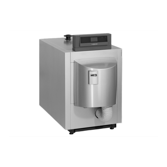
- Page 1 VIESMANN Service instructions for contractors Vitocrossal 200 Type CM2B, 87 to 311 kW Gas condensing boiler with MatriX radiant burner Permissible operating pressure 6 bar (0.6 MPa) For applicability, see the last page VITOCROSSAL 200 Please keep safe. 5812086 GB/en 9/2017...
- Page 2 Hot surfaces can cause burns. Replace faulty components only with genuine ■ Before maintenance and service work, switch Viessmann spare parts. OFF the appliance and let it cool down. Never touch hot surfaces on the boiler, burner, ■ flue system or pipework.
- Page 3 For replacements, use only original spare parts supplied or approved by Viessmann. Safety instructions for operating the system If you smell gas Condensate Danger...
-
Page 4: Table Of Contents
Index Index 1. Information Symbols ....................Intended use ..................Product information ................2. Commissioning, inspec- Steps - commissioning, inspection and maintenance ......tion, maintenance 3. Vitotronic control unit Setting the codes at the control unit ............33 codes 4. Burner control unit Burner control unit VUC 310 .............. -
Page 5: Information Symbols
Information Symbols The steps in connection with commissioning, inspec- Symbol Meaning tion and maintenance are found in the "Commission- Reference to other document containing ing, inspection and maintenance" section and identified further information as follows: Step in a diagram: Symbol Meaning The numbers correspond to the order in Steps required during commissioning... -
Page 6: Product Information
Information Product information Vitocrossal 200, type CM2B 87 to 311 kW with permis- Gas condensing boiler for natural gas E and LL, with sible operating pressure 6 bar (0.6 MPa). modulating MatriX radiant burner. -
Page 7: Commissioning, Inspec-Steps - Commissioning, Inspection And Maintenance
Commissioning, inspection, maintenance Steps - commissioning, inspection and maintenance Commissioning steps Inspection steps Maintenance steps Page • 1. Checking the high limit safety cut-out setting..............• 2. Filling the heating system with water and venting............• 3. Filling the trap with water....................•... - Page 8 Commissioning, inspection, maintenance Steps - commissioning, inspection and… (cont.) Commissioning steps Inspection steps Maintenance steps Page • • • 38. Checking the installation room ventilation air apertures..........31 • 39. Instructing the system user....................32 • 40. Operating and service documents................... 32...
-
Page 9: Checking The High Limit Safety Cut-Out Setting
Commissioning, inspection, maintenance Checking the high limit safety cut-out setting The high limit safety cut-out must not be set higher Control unit installation and service instructions than 110 °C; if required, set it to a maximum of 110 °C. Filling the heating system with water and venting Record the volume filled, water hardness and pH value Note on page 72. - Page 10 Commissioning, inspection, maintenance Commissioning the system (cont.) 01. Check the heating system pressure. Permiss. operating 6 bar (0.6 MPa) pressure Minimum operating 0.5 bar (50 kPa) pressure Danger If the operating pressure is too low, excess temperatures in the flue system can cause leaks.
-
Page 11: Checking The Motor-Controlled Flue Gas Damper (If Installed)
Commissioning, inspection, maintenance Commissioning the system (cont.) 10. Check all gaskets and plugs, and retighten if nec- essary. Note We recommend checking all connections on the heating water side for leaks approx. every 500 hours run. See page 21. 11. Check the boiler door and flue gas cover a few days after commissioning. - Page 12 Commissioning, inspection, maintenance Converting to natural gas LL (cont.) Conversion for 87 kW 01. Close the gas shut-off valve. 02. Turn off the system ON/OFF switch at the user interface of the control unit. 03. Switch OFF the mains isolator (outside the instal- lation room) or isolate the mains power and secure against unintentional reconnection.
- Page 13 Commissioning, inspection, maintenance Converting to natural gas LL (cont.) Conversion for 115 to 311 kW 01. Close the gas shut-off valve. 02. Switch OFF the system ON/OFF switch on the control unit. 03. Switch OFF the mains isolator (outside the instal- lation room) or isolate the mains power and secure against unintentional reconnection.
-
Page 14: Reducing The Heating Output (If Required)
Commissioning, inspection, maintenance Reducing the heating output (if required) The maximum heating output of the burner can be reduced if required. 1. Press S and hold for longer than 2 s. Status Service flashes. 2. Press until the display shows "6" under Service. 3. - Page 15 Commissioning, inspection, maintenance Checking static pressure and supply pressure (cont.) Supply pressure Note 3. Record the actual value in the report (on See type plate for supply pressures for operation with page 73). other country-specific gas types. 4. Close the gas shut-off valve. 1.
-
Page 16: Checking The Rotary Damper Setting
Commissioning, inspection, maintenance Checking the rotary damper setting For 246 and 311 kW rated heating output only Fig. 8 1. Open the gas shut-off valve. 4. Start the burner. 2. Check the position of the rotary damper with the 5. Check the position of the rotary damper during the burner in idle mode. - Page 17 Commissioning, inspection, maintenance Checking the CO content (cont.) Permissible CO content Gas type con- Rated heating output in kW tent Natural gas Upper heat- 7.1 - 10.2 % 7.0 - 10.1 % 7.0 - 10.1 % 7.1 - 10.2 % 7.1 - 10.2 % 7.1 - 10.2 % ing output (100 %)
- Page 18 Commissioning, inspection, maintenance Checking the CO content (cont.) 4. If the CO content needs adjusting: Turn adjusting screw in small increments. Con- tinue turning until CO content falls within the specified range. Turning clockwise ■ content falls → ■ Turning anti-clockwise content rises →...
-
Page 19: Checking The Co Content
Commissioning, inspection, maintenance Checking the CO content (cont.) test at the upper heating output (115 to 311 kW) 1. Press until the service display has counted up to "100" (= 100 %). 2. Check the CO content at the flue pipe. For permissible CO content, see above table. -
Page 20: Checking The Flue Gas Temperature
Commissioning, inspection, maintenance Checking the flue gas temperature Enter actual value into the report in the appendix. Displaying the ionisation current Note 08. Record the actual value in the report. The ionisation current must be called up via the burner control unit. -
Page 21: Cleaning The Combustion Chamber And Heating Surfaces
Commissioning, inspection, maintenance Cleaning the combustion chamber and heating surfaces Thoroughly clean the combustion chamber and heat- Remove coatings and surface discolouration (yellow- ■ ing surfaces with a water jet. brown) with slightly acidic, chloride-free cleaning agents based on phosphoric acid (e.g. Antox 75 E). Please note ■... -
Page 22: Cleaning The Condensate Drain Pipe System And Trap
4. Clean the neutralising system (if installed) in accordance with the manufacturer's instructions. Neutralising system operating instructions Note Neutralising agent can be obtained from Viessmann by quoting part no. 9521702. Fig. 15 5. Undo and flush lower section of trap 6. Fill lower section with water and secure. -
Page 23: Checking The Burner Gauze Assembly
Commissioning, inspection, maintenance Checking the burner gauze assembly Danger Escaping gas leads to a risk of explosion. Close the gas shut-off valve. Undo fitting on the gas supply pipe. 2. Undo the screws on the boiler door and open the door. -
Page 24: Cleaning The Burner
Commissioning, inspection, maintenance Cleaning the burner 1. Release clamps and disconnect control cables. 87 kW 2. Undo fitting on gas supply pipe 3. Remove Venturi mixing pipe from fan 4. Remove all connecting cables from the gas train. 5. Remove Venturi mixing pipe with gas train and gas supply pipe Note... - Page 25 Commissioning, inspection, maintenance Fitting the burner (cont.) 115 to 311 kW 5. Reinstall control cables using clamps. For connec- tion diagrams, see following pages. Please note Incorrectly connected control cables can cause malfunctions. Ensure that control cables are connected correctly. 6.
- Page 26 Commissioning, inspection, maintenance Fitting the burner (cont.) Gas train Enriching nozzle in hose 87 kW 2 mm Hose dimensions Hose dimensions Length in mm Length in mm Pressure-jet gas burners 115 to 186 kW Fig. 24 Air pressure switch 2 Boiler door Choke valve Air pressure switch 1...
- Page 27 Commissioning, inspection, maintenance Fitting the burner (cont.) Venturi mixing pipe Enriching nozzle in hose 115/142 kW 1 mm 186 kW 1.6 mm Hose dimensions Hose dimensions Length in mm Length in mm Pressure-jet gas burners 246 to 311 kW Fig. 25 Air pressure switch 2 Boiler door Air pressure switch 1...
-
Page 28: Closing The Boiler Door
Commissioning, inspection, maintenance Closing the boiler door 18 Nm Fig. 26 1. If the burner has been removed, hook the burner 3. To ensure that the boiler door closes tightly, adjust onto the hinge bracket and secure it with a split the clearance between the front panel and hinge pin. -
Page 29: Checking The Gas Train Valves For Tightness
1 mbar (0.1 kPa) within 5 min. Otherwise there is a leak. In this case, return the gas train to your local Viessmann sales office for tests. 7. After testing, close both test connectors by tighten- ing the respective screws. -
Page 30: Checking Gas Connections For Tightness
Commissioning, inspection, maintenance Checking gas connections for tightness Danger 2. Open the gas shut-off valve. Escaping gas leads to a risk of explosion. Always carry out the following steps: 3. Check the inlet joints of the gas train for tightness. Please note 4. -
Page 31: Checking The Water Quality
Commissioning, inspection, maintenance Checking the water quality Enter the amount of top-up water, the total hardness and the pH value in the tables on page 72. For water quality requirements, see page 70. Checking the safety valve function Checking the temperature controller setting if a building management system is used (DCC system) Please note Shutting down from full load can result in high... - Page 32 Commissioning, inspection, maintenance Instructing the system user The system installer should hand the operating instruc- This includes all components installed as accessories, tions to the system user and instruct the user in oper- e.g. remote control units. In addition, the system instal- ating the system.
-
Page 33: Vitotronic Control Unit Setting The Codes At The Control Unit
Vitotronic control unit codes Setting the codes at the control unit Vitotronic service instructions In conjunction with the following control units: ■ Vitotronic 100, type CC1E ■ Vitotronic 200, type CO1E Vitotronic 300, type CM1E ■ Parameters in the boiler group Rated heating output in kW Coding card Settings... -
Page 34: Burner Control Unit Burner Control Unit Vuc 310
Burner control unit Burner control unit VUC 310 Display and programming unit A display and programming unit is integrated into the Note burner control unit. The display screen shows the rele- Depending on the system configuration, the display vant operating status, the service and parameter sta- and control functions can in part also be carried out on tus, as well as any fault or error messages. -
Page 35: Info Display/Configuration Display
Burner control unit Burner control unit VUC 310 (cont.) Display Meaning Status Service Fig. 30 Example Status Service Operation with flame After flame post-purge Dwell program, no air pressure Dwell program, no gas pressure or mains undervoltage Forced ventilation if no flame formation has been detected. Safety shutdown due to flame tear-off Info display/configuration display The information display and the configuration display... - Page 36 Burner control unit Burner control unit VUC 310 (cont.) Configurations: Menu Description point Changeover from the operating display of the burner control unit phase to other proc- ess information Configuration of control function operating parameters Menu point "5" is used to display the following process information: Sub-menu point Process information Units/scale...
-
Page 37: Resetting Operating Parameters To Their Delivered Condition
Burner control unit Burner control unit VUC 310 (cont.) Resetting operating parameters to their delivered condition 1. S longer than 2 s, " " flashes. 5. S "1" is shown under Status and "dEL" under Serv- ice. until "6" is shown under Service. 6. -
Page 38: Burner Control Unit Flow Chart
Burner control unit Burner control unit flow chart Fig. 31 Description of state: Phase Display Description Duration System start "A" System start 10 s Initialisation of fault meter 0.1 s Mains test, gas pressure Fan ramp-up, system start max. 20 s Forced ventilation, system start 20 s... - Page 39 Burner control unit Burner control unit flow chart (cont.) Phase Display Description Duration Relay test "P" Fan ramp-up for test max. 20 s Safety relay test 0.9 s Disable relays BV1 and BV2. 0.9 s Relays test BV1 and BV2 0.9 s Ignition relay test 0.9 s...
-
Page 40: Troubleshooting Fault Display
Troubleshooting Fault display If the burner control unit switches to a fault state, the Fault code of the most recent fault (see table from fault display is automatically activated. The most page 40) recent fault is then displayed. The fault LED is also illu- minated in the case of a non-lockout fault, or flashes 1. - Page 41 Troubleshooting Fault codes (cont.) Fault code dis- System characteristics Cause Measures played F b7 Burner control unit in a fault Coding card not inserted Insert coding card; check coding state; system cooling down; in the burner control unit; card, replace if required. burner control unit locked out.
- Page 42 Troubleshooting Fault codes (cont.) Fault code dis- System characteristics Cause Measures played F F4 Poor start-up characteristics, Compensation lines not Check compensation lines and rotary damper does not connected, servomotor connections (see page 66), re- close, solenoid valve does faulty, servomotor power place connecting cables, replace not switch.
-
Page 43: Internal System Faults
Troubleshooting Fault codes (cont.) Fault code dis- System characteristics Cause Measures played F F9 No feedback from fan Fan faulty, external fan Check cable " A", check exter- a-Ö power supply not connec- nal power supply, replace cable or ted or faulty, cable " A"... -
Page 44: Faults Without Fault Display
Troubleshooting Fault codes (cont.) Detailed er- Component/signal Cause of fault Measure ror code Plug 90 T8 High switching se- Check whether external voltage present. quence, switch flutters Check on-site connection. External voltage Plug 90 T7 SK High switching se- Check whether external voltage present. quence, switch flutters Check on-site connection. -
Page 45: Parts Lists Overview Of Assemblies
Parts lists Overview of assemblies The following details are required when ordering parts: ■ Serial no. (see type plate ■ Assembly (from this parts list) Position number of the individual part within the ■ assembly (from this parts list) Fig. 33 Type plate Thermal insulation assembly Burner assembly... -
Page 46: Boiler Assembly
Parts lists Boiler assembly 0001 0004 0003 0005 Fig. 34... - Page 47 Parts lists Boiler assembly (cont.) Pos. Part 0001 CM2 flue gas cover with gasket 0003 Stench trap 0004 CM2 hinge bracket 0005 Base frame...
-
Page 48: Thermal Insulation Assembly
Parts lists Thermal insulation assembly 0008 0007 0015 0003 0015 0006 0005 0016 0011 0004 0009 0014 0001 0010 0013 0002 0012 0017 0018 0006 0014 Fig. 35... - Page 49 0010 Thermal insulation jacket 0011 Thermal insulation mat, back 0012 Thermal insulation mat, front 0013 Right and left cover panel 0014 Vitocrossal 200 logo 0015 Edge protection 0016 Fixing rail, top 0017 Fixing rail, bottom 0018 Side panel, right front...
-
Page 50: Gas Burner Assembly, 87 Kw
Parts lists Gas burner assembly, 87 kW 0031 0009 0006 0005 0006 0011 0003 0002 0020 0010 0016 0018 0017 0009 0008 0003 0009 0020 0012 0001 0007 0002 0009 0028 0003 0021 0006 0009 0009 0013 0017 0015 0014 0027 0019 0004... - Page 51 Parts lists Gas burner assembly, 87 kW (cont.) Pos. Part 0001 Boiler door 0002 Thermal insulation block 0003 Sealing pack, boiler door 0004 Small parts 0005 Burner gauze assembly 0006 Burner gauze assembly gasket 0007 Ionisation electrode 0008 Ignition electrode block 0009 Electrode block gasket 0010...
-
Page 52: Gas Burner Assembly, 115, 142 And 186 Kw
Parts lists Gas burner assembly, 115, 142 and 186 kW 0031 0022 0020 0003 0006 0018 0003 0020 0002 0010 0011 0016 0005 0008 0006 0009 0009 0009 0015 0007 0009 0017 0023 0009 0001 0002 0021 0012 0003 0006 0009 0014 0013... - Page 53 Parts lists Gas burner assembly, 115, 142 and 186 kW (cont.) Pos. Part 0001 Boiler door 0002 Thermal insulation block 0003 Sealing pack, boiler door 0004 Small parts 0005 Burner gauze assembly 0006 Burner gauze assembly gasket 0007 Ionisation electrode 0008 Ignition electrode block 0009...
-
Page 54: Gas Burner Assembly, 246 And 311 Kw
Parts lists Gas burner assembly, 246 and 311 kW 0005 0006 0009 0018 0006 0018 0009 0008 0003 0009 0020 0009 0010 0011 0002 0007 0009 0003 0001 0017 0002 0003 0012 0006 0009 0017 0013 0015 0023 0004 0023 0014 0024 0026... - Page 55 Parts lists Gas burner assembly, 246 and 311 kW (cont.) Pos. Part 0001 Boiler door 0002 Thermal insulation block 0003 Sealing pack, boiler door 0004 Small parts 0005 Burner gauze assembly 0006 Burner gauze assembly gasket 0007 Ionisation electrode 0008 Ignition electrode block 0009 Electrode block gasket...
-
Page 56: Burner Control Unit Assembly, 87 Kw
Parts lists Burner control unit assembly, 87 kW 0001 0002 0004 0005 0003 0006 0007 0012 0014 0017 0016 Fig. 39... - Page 57 Parts lists Burner control unit assembly, 87 kW (cont.) Pos. Part 0001 Burner control unit VUC310 0002 Programming unit HI201-D01.001 0003 Connecting cable, 38 bypass 0004 Ionisation cable 11/earth 0005 Ignition transformer connecting cable 54 0006 Connecting cable, gas train/gas pressure switch 0007 Gas fan connecting cable 0012...
-
Page 58: Burner Control Unit Assembly, 115, 142 And 186 Kw
Parts lists Burner control unit assembly, 115, 142 and 186 kW 0001 0002 0005 0004 0003 0006 0007 0012 0016 0017 0014 Fig. 40... - Page 59 Parts lists Burner control unit assembly, 115, 142 and 186… (cont.) Pos. Part 0001 Burner control unit VUC310 0002 Programming unit HI201-D01.001 0003 Connecting cable, 38 bypass 0004 Ionisation cable 11/earth 0005 Ignition transformer connecting cable 54 0006 Gas train connecting cable 0007 Gas fan connecting cable 0012...
-
Page 60: Burner Control Unit Assembly, 246 And 311 Kw
Parts lists Burner control unit assembly, 246 and 311 kW 0001 0002 0004 0005 0003 0006 0007 0008 0012 0017 0014 0016 Fig. 41... - Page 61 Parts lists Burner control unit assembly, 246 and 311 kW (cont.) Pos. Part 0001 Burner control unit VUC310 0002 Programming unit HI201-D01.001 0003 Connecting cable, 38 bypass 0004 Ionisation cable 11/earth 0005 Ignition transformer connecting cable 54 0006 Gas train connecting cable 0007 Gas fan connecting cable 0008...
-
Page 62: Miscellaneous Assembly
Parts lists Miscellaneous assembly 0001 0002 0003 0004 Fig. 42... - Page 63 Parts lists Miscellaneous assembly (cont.) Pos. Part 0001 Touch-up spray paint, Vitosilver, 150 ml can 0002 Touch-up paint stick, Vitosilver 0003 Installation instructions 0004 Service instructions...
-
Page 64: Component Overview Overview Of Burner Components
Component overview Overview of burner components Pressure-jet gas burner 87 kW Fig. 43 Boiler door Gas train Gas pressure switch Display and programming unit Inlet adaptor for room sealed operation (optional) Gas supply pipe Burner gauze assembly Gas shut-off valve Ignition electrode Air pressure switch 2 Ionisation electrode... -
Page 65: Pressure-Jet Gas Burners 246 To 311 Kw
Component overview Overview of burner components (cont.) Ignition electrode Suppressor choke box Ionisation electrode Ignition unit Thermal insulation block Burner control unit Pressure-jet gas burners 246 to 311 kW Fig. 45 Boiler door Rotary damper with drive Air pressure switch 1 Burner gauze assembly Ignition electrode Display and programming unit... -
Page 66: Function Description Air Pressure Switch
Function description Air pressure switch Fan pressure monitoring (air pressure switch 1 - 131) The switching threshold of air pressure switch 1 (131) Rated heating LDW1 setting value in mbar (Pa) is monitored in all fan ramp-up phases and checked output in kW during modulating burner operation. - Page 67 Function description Air pressure switch (cont.) For 115, 142 and 186 kW, remove screw and attach Check control cables: connecting cable. Check for tightness. ■ Connection and kink-free routing ■ Application and seating of retaining clips...
-
Page 68: Connection Diagrams Burner Control Unit Connection Diagram
Connection diagrams Burner control unit connection diagram Fig. 47 Burner control unit VUC 310 Gas pressure switch 1 Fan motor with PWM control and feedback Air pressure switch 2 Air pressure switch 1 Display and programming unit... - Page 69 Connection diagrams Burner control unit connection diagram (cont.) Fig. 48 Burner control unit VUC 310 F1 Backup fuse Flame monitor with ionisation current F2 Backup fuse F6 High limit safety cut-out Vitotronic control unit F7 Temperature controller Servomotor for rotary damper or 2/2-way solenoid valve H1 Hours run meter, modulation Ignition unit...
- Page 70 Water quality requirements Water quality requirements Note Prevention of damage due to scaling Observing the following requirements is necessary to safeguard your warranty rights. Prevent excessive scale build-up (calcium carbonate) The warranty excludes damage due to corrosion and on the heating surfaces. For heating systems with scaling.
- Page 71 Water quality requirements (cont.) Failure to observe the requirements of VDI Guideline Correctly sized sealed unvented systems operating at 2035 can result in damaging limescale deposits. In the correct pressure, e.g. systems with expansion ves- such cases, the service life of the installed boilers will, sel, offer good protection against the ingress of air- most often, already have been reduced.
-
Page 72: Reports
Reports Reports Fill water report Fill water Top-up water Meter reading Total water volume Date — — — — — — — — — — — — — — — — — — — Max. fill volume: ......m Water quality report Total hardness pH value Water treatment... - Page 73 Reports Reports (cont.) Settings and measurement values Commissioning Maintenance/service Static pressure mbar Supply pressure (flow pressure) for natural gas E mbar for natural gas LL mbar Tick gas type. Carbon dioxide content CO At the upper rated heat- actual % by vol. ■...
-
Page 74: Specification
Specification Specification Rated heating output = 50/30 29 - 87 38 - 115 47 - 142 47 - 186 82 - 246 104 - 311 = 80/60 27 - 80 35 - 105 43 - 130 43 - 170 75 - 225 95 - 285 Rated heat input Product ID... - Page 75 If using the Vitocrossal 200 with moisture-resistant chimneys, the draught must be no more than 0 Pa. Standard values resulting from sound pressure level testing cannot be guaranteed, as sound pressure level tests are al-...
- Page 76 Specification Specification (cont.) Rated heat input Upper ■ Lower ■ Total weight (with burner hood 37.5 41.0 41.0 41.0 42.0 42.0 and combination valve) Gas supply pressure mbar 20 to 50 20 to 50 20 to 50 20 to 50 20 to 50 20 to 50 2 to 5...
-
Page 77: Final Decommissioning Final Decommissioning And Disposal
Final decommissioning Final decommissioning and disposal Viessmann products can be recycled. Components For decommissioning the system, isolate the system and substances from the system are not part of ordi- from the power supply and allow components to cool nary household waste. -
Page 78: Certificates Eu Declaration Of Conformity
EU Declaration of Conformity Vitocrossal 200, type CM2B, 87 to 311 (80 to 285) kW, with Vitotronic boiler control unit and MatriX burner We, Viessmann Werke GmbH & Co. KG, D-35107 Allendorf, declare as sole responsible body that the named... -
Page 79: Manufacturer's Certificate According To The 1St German Immissions Order (Bimschv)
Manufacturer’s certificate according to the 1st German Immissions Order (BImSchV) We, Viessmann Werke GmbH & Co. KG, D-35107 Allendorf, confirm that the product Vitocrossal 200, type CM2B, complies with the following conditions stipulated by the 1st German Immissions Order (BImSchV): ■... -
Page 80: Keyword Index
Keyword index Keyword index Air pressure switch.............66 Heating surfaces, cleaning.........21 Heating system – Filling with water............9 Boiler door, closing.............28 High limit safety cut-out..........9 Boiler door, opening........... 20 Boiler water requirements.......... 70 Burner Ignition electrodes, checking........23 – Cleaning..............24 Instructing the system user........32 –... - Page 81 Keyword index Keyword index (cont.) Water quality – Checking..............31 – Report..............72 – Requirements............70 Water quality, requirements........70...
- Page 84 Applicability Serial No.: 7639174 7639175 7639176 7639177 7639178 7639179 Viessmann Werke GmbH & Co. KG Viessmann Limited D-35107 Allendorf Hortonwood 30, Telford Telephone: +49 6452 70-0 Shropshire, TF1 7YP, GB Fax: +49 6452 70-2780 Telephone: +44 1952 675000 www.viessmann.com Fax: +44 1952 675040...
Need help?
Do you have a question about the Vitocrossal 200 and is the answer not in the manual?
Questions and answers