Table of Contents
Advertisement
Refrigeration units EVO-COOL®
Ensure compliance with the following instructions prior to beginning work on the Refrigeration unit:
Installation, cleaning maintenance and repair work must be
performed only by a refrigeration specialist company.
Technical modifi cations and manipulation are prohibited.
Non-compliance will result in forfeiture of all warranty claims.
General notice (liability): the details of this technical documents serve for description. Consents regarding the availability of certain features or
regarding a certain purpose always require a special written agreement.
Page 1
Installation and
operating Instructions
6008309-01 GB
Work on the Refrigeration unit is authorised only when the mains
plug has been removed. The Refrigeration unit must be protec-
ted against unauthorized activation by appropriate means
(e.s. warning sign). The directives, VDE 0105 Part 1, for working
on electrical equipment must be complied with.
We reserve the right to make technical changes! Status as of 02.15
GB
Advertisement
Table of Contents

Related Manuals for Viessmann EVO-COOL Series


Summary of Contents for Viessmann EVO-COOL Series
-
Page 1: Installation And Operating Instructions
Refrigeration units EVO-COOL® Installation and operating Instructions 6008309-01 GB Ensure compliance with the following instructions prior to beginning work on the Refrigeration unit: Installation, cleaning maintenance and repair work must be Work on the Refrigeration unit is authorised only when the mains performed only by a refrigeration specialist company. -
Page 2: Table Of Contents
Fault rectification 11.1 Refrigeration unit is not running Installation of a EVO-COOL® in a 11.2 Refrigeration unit is running, but the display is not Viessmann coldroom working 11.3 Thermal detector defective. • RF–breakage / short circuit Electrical power supply cold room •... -
Page 3: Description
Description Standards and regulations The units are designed for the prescribed temperature The EVO-COOL® refrigeration unit has been built and in- anges. If they are operated outside the prescribed tempe- spected according to the standards and regulations valid rature range for several days, the possibility of a serious at the time of manufacture. -
Page 4: Transport
Transport Decommissioning The Refrigeration unit must be transported in its opera- Temporary decommissioning ting position due to oil in the compressor. For possible further transport, only the original packaging may be The refrigeration unit is decommissioned as follows: used. - Turn the knob to Standby mode then press to confi rm. - Select Standby Yes. -
Page 5: Cleaning And Maintenance Of The Refrigeration Unit
Cleaning and maintenance of the Refrigeration unit Attention! The mains plug must be removed from the socket and protected against re-insertion for all cleaning and maintenance work. Following commissioning, the Refrigeration unit should bechecked periodically and cleaned as necessary. The time span between the checks or cleaning should be established based on the level of contamination. -
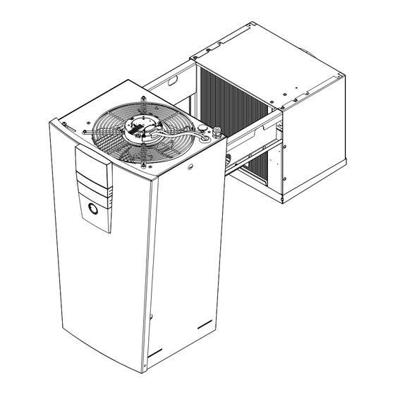
Page 6: Installation Of A Evo-Cool® In A Viessmann Coldroom
Installation of a EVO-COOL® in a Viessmann coldroom Sufficient free space must be provided for the intake and discharge openings on the left side of the refrigeration unit in order to warrant a good air flow: - at least 250 mm from all ventilation openings. - Page 7 Hang the unit on the storage cell wall while pushing against it from the outside. Slide the holding angle against the inside cell wall and tighten it securely with one or two bolts. Loosen the locking screws (2 ea.) on the front access cover.
- Page 8 Slide the enclosed plastic collar (D) over the defrost water drain hose (B). Guide the defrost water drain heater (A) completely through the defrost water drain hose (B), and in this pro- cess, for easier insertion, the defrost water drain hose (B) must be pulled as much in a straight line as possible.
- Page 9 Push the enclosed defrost water tray with the side clips (P) in the lower guide up to the end of the evaporator line to the back. Then push the tray upwards and ca. 10 mm to the back, again. The defrost water tray is correctly positioned if the side clips (P) on the defrost water tray are positioned on the metal clips (Q).
-
Page 10: Electrical Power Supply Cold Room
Electrical power supply cold room Mains connection 230V AC A 4-pole socket outlet is located on the intake-side of the Refri- via multi-pin connector geration evaporator unit for the electrical power supply to the loads attached to the coldroom, with a total power capacity of max. -
Page 11: Power Supply Connection And Commissioning
Power supply connection and commissioning Attention! The electrical power supply should first be connected at commissioning - Risk of life! Work on the power supply connector and protection devices must be carried out by a specialist company, in accordance with IEC 364, local regulations and the connection conditions of the respective energy supply company! Insert the mains plug into a properly grounded outlet with personal protection measures (fault current circuit breaker) -
Page 12: Defrosting
Defrosting Relay Defrosting process When the defrost function activates, the compressor and the Compressor fan are switched off and the heater for the defrost water hose is switched on. Solenoid valve Bypass Once the defrost water hose lead time has passed, the com- pressor switches on and the bypass valve opens. -
Page 13: Defrosting Options
Defrosting options - The air flow should not be directed at the doors and pressure compensation valves. Pressure compensation Defrosting cycle valves must always be installed in a position where The defrosting process is continually triggered at set they are barely influenced by the air flow. intervals. -
Page 14: Cooling Mode
Cooling mode How the cooling mode works Relay After switching on the unit (Standby => No; see Point 8 Compressor ‘First steps’), the cooling mode activates. If the unit was Solenoid valve only recently connected to the mains, the compressor Bypass standstill time (usually three minutes) passes. -
Page 15: First Steps Evo-Cool
First steps EVO-COOL® Check the intactness of the refrigeration unit. If the EVO-COOL® is in order, it can be connected to the network according to the specifi cation plate. The control unit comprises the functional units of a display, a rotary knob, a push button, the USB interface (concealed behind the cover over the display) and the mains connection. -
Page 16: Operation Of The Regulation
9. Operation of the regulation Menu Enabling A 5-digit code can be used for log in. The unit must be released for all operation, including Standby mode or temperature changes. This provides protection against accidental changes. In the original state, the passwords for the user 12345 the service 90210 If the access rights are to be modifi ed or for specifi c users they are inaccessible, the... -
Page 17: Menu Settings
9.3 Menu Settings Presetting Submenu 1 Submenu 2 Values Description CS Cooler FS Freezer German After changing the language setting, the unit must be Language Up to 8 diff erent languages can be stored. The restarted. English standard languages are German, English and French. In French order to activate the changeover to another language, Turkish... - Page 18 Presetting Submenu 1 Submenu 2 Values Description CS Cooler FS Freezer Wall-han- Wall-hanging unit: in the case of redundancy, all units in the bus ging system simultaneously begin defrosting. unit Wall- Wall-hanging Type hanging Ceiling unit: units begin defrosting separately. unit Ceiling- unit...
- Page 19 Presetting Submenu 1 Submenu 2 Values Description CS Cooler FS Freezer After the defrosting process, a waiting time is applied until the normal operating mode (cool- ing) is returned. In the case of Drain down 0 min to 10 min 3 min 3 min hot gas defrosting, the compres-...
- Page 20 Presetting Submenu 1 Submenu 2 Values Description CS Cooler FS Freezer Limiting Mute time off 0 min to 99 min 60 min 60 min Duration for which a confi rmed error is suppressed. values/ alarm Alarm delay Time interval after which the upper or lower tem- time for tem- 0 min to 99 min 60 min...
- Page 21 Presetting Submenu 1 Submenu 2 Values Description CS Cooler FS Freezer Time Time Time setting. Date Date Date setting. Opera- The system number is displayed in the upper line. If ting field the data logger is activated, the licence number also number in Data logger appears in the second line.
-
Page 22: Menu Information
9.4 Menu Information This menu item can be viewed without approval. All statuses that can be registered by the control unit are dis- played. The brief description on the right is repeated again on the lower edge using clearer names. Submenu 1 Submenü... -
Page 23: Menu Logbook
Menu LogBook 9.5.1 Mode of operation All recordable faults are documented in the log book and stored in a continuously updated ring memory. Depending on the volume, the faults are stored for at least three months and then overwritten. The data can be exported and evaluated (*txt for- mat). -
Page 24: Menu Program
9.6 Menu Program Submenu 1 Submenu 2 Values CS Cooler FS Freezer Description Cooling range -5°C to +20°C Setting value +5°C Temperature +5°C -20°C Target temperature input. Freezing range -5°C to -25°C Setting value -20°C Switching from standby to Standby Yes / No cooling. -
Page 25: Menu Change Board
Data access via USB connection Update Software A software update is possible USB port The current software status is shown on the homepage of the Viessmann Kühlsysteme GmbH (www.viessmann.de/kuehlsysteme). For the download, the e-mail address and the Knob company must be specifi ed. -
Page 26: Bus Operation Faults
Bus mode 10.1 Connection of the units and the display Emergency The units are connected together using a CAT5E data switchoff lower Switch for bus address cable and an RJ45 plug connector. The display must "Off" always be connected using the upper socket (see circuit Display and bus diagram). -
Page 27: Fault Rectification
11. Fault rectification Attention: Before working on electrical components and on the unit the equipment must always be disconnected from mains! Risk through electrical power and rotating (fan) and hot parts (pipes, condenser, heat exchanger)! Problem Description / Reason Correction Refrigeration unit is not Power plug is not Connect the power plug and check the mains fuse. -
Page 28: Cold Room Temperature Too High
Problem Description / Reason Correction Cold room temperature too The upper alarm If the temperature continues to be above the alarm limit after acknowledg- high. limit for temperature ment of the fault, the delay time will start over. monitoring was ex- Check whether the doors are closed and the machine is cooling. -
Page 29: Refrigeration Circulation Schematic
12. Refrigeration circulation schematic P> Compressor Pressure line Hot gas line / dripping tray Air cooled condenser High pressure switch (low pressure switch) Inside heat exchanger Collector - drier Thermal expansion valve Evaporator 10 Suction line 11 Coldroom 12 Magnetic valve, fluid line 13 Magnetic valve, hot gas defrosting 14 Schrader-test connectors 15 Solenoid valve pressure line... -
Page 30: Electrical Circuit Diagram For 230V / 1~ / 50Hz
13. Electrical circuit diagram for 230V / 1~ / 50Hz Power board (Part number 00173920) F 6,3A tr Alarm contact potential free GEYE Electric supply 4-pole 230 V AC 50 Hz multi-contact 16 A K-characteristic plug Magnetic Magnetic personal protection Oil sump valve valve... - Page 31 12V+ 12V+ 12V+ 12V+ 12V+ 12V+ 12V+ 12V+ 12V+ ϑ ϑ ϑ ϑ +12V X5 /11 X5 / 11 Optional for emergency switch X5 /12 9 Volt Display (Part number 00173921) USB port for data exchange Ethernet interface RJ 45 DIP switch Adresse conductor coloring...
-
Page 32: Electrical Circuit Diagram For 400V /3~ /50Hz
14. Electrical circuit diagram for 400V /3~ /50Hz Power board (Part number 00173920) F 6,3A tr Alarm contact potential free GEYE 4-pole multi-contact plug Magnetic Magnetic Oil sump Condenser Condenser Heating in Evaporator fan valve valve heating fan A fan B the defrost 230V 1~ Hot gas... - Page 33 12V+ 12V+ 12V+ 12V+ 12V+ 12V+ 12V+ 12V+ 12V+ ϑ ϑ ϑ ϑ Optional for emergency switch 9 Volt +12V X5 / 11 X5 /11 X5 /12 Display (Part number 00173921) USB port for data exchange Ethernet interface RJ 45 Wiring in the case of HD/ND combination switch (optional)
-
Page 34: Technical Data
15. Technical data EVO-COOL® refrigeration units Description CS 500 CS 900 CS 1300 CS 1500 CS 2000 CS 2500 CS 3000 Coldroom temperature adjustment -5°C to +20°C range Admissible ambient temperature +1°C to +43°C Size Cooling capacity 634 W 1050 W 1350 W 1505 W 2035 W... -
Page 35: Explanation Of Conformance Ce
16. Explanation of Conformance CE Engines-rule 2006/42/EG EMV-rule 2004/108/EG Product Refrigeration and deep-freeze units Viessmann Type EVO-COOL® CS 0500, CS 0900, CS 1300, CS 1500, CS 2000, CS 2500, CS 3000 EVO-COOL® FS 0900, FS 1200, FS 1400, FS 2000, FS 2500, FS 3000 is developed, constructed and manufactured according to the EC-rules as meutioned above by sole responsibility of Viessmann Kühlsysteme GmbH... - Page 36 Viessmann Kühlsysteme GmbH Schleizer Straße 100 95030 Hof/Saale Telefon +49 9281 814-0 Telefax +49 9281 814-269 kuehlsysteme@viessmann.de www.viessmann.de/kuehlsysteme Your responsible refrigeration service: General notice (liability): the details of this technical documents serve for description. Consents regarding the availability of certain features or regarding a certain purpose always require a special written agreement.
Need help?
Do you have a question about the EVO-COOL Series and is the answer not in the manual?
Questions and answers