Viessmann Vitocrossal Installation Instructions For Contractors
Hide thumbs
Also See for Vitocrossal:
- Service instructions manual (112 pages) ,
- Installation instructions manual (44 pages) ,
- Installation instructions manual (40 pages)

Related Manuals for Viessmann Vitocrossal


Summary of Contents for Viessmann Vitocrossal
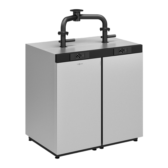
- Page 1 VIESMANN Installation instructions for contractors Vitocrossal Type CRU, 800 to 1000 kW Gas condensing boiler VITOCROSSAL Dispose after installation. 5816716 GB 1/2018...
- Page 2 Safety instructions Please follow these safety instructions closely to prevent accidents and material losses. Safety instructions explained Danger Note This symbol warns against the risk of injury. Details identified by the word "Note" contain additional information. Please note This symbol warns against the risk of material losses and environmental pollution.
-
Page 3: Table Of Contents
Index Information Disposal of packaging ................Symbols ....................Intended use ..................Preparing for installation Clearance dimensions ................Thermal insulation components ............. Thermal insulation pack 1 ..............■ Thermal insulation pack 2 ..............■ Installation sequence Siting the boiler ..................10 Assembling the heat exchanger and combustion chamber module .. -
Page 4: Information Disposal Of Packaging
Disposal of packaging Disposal of packaging DE: Use the disposal system organised by Viessmann. Please dispose of packaging waste in line with statu- AT: Use the ARA statutory disposal system (Altstoff tory regulations. Recycling Austria AG, licence number 5766). CH: Packaging waste is disposed of by the HVAC contractor. - Page 5 Intended use (cont.) Every other use will be deemed to be inappropriate. Any usage beyond this must be approved by the man- Any resulting losses are excluded from the manufac- ufacturer for the individual case. turer's liability. Intended use also includes the adherence to mainte- nance and inspection intervals.
-
Page 6: Preparing For Installation Clearance Dimensions
Clearance dimensions Note The hinge pins can be repositioned so that the boiler door opens to the left. 200 (100) Fig. 3 500 (50) Anti-vibration boiler supports Permissible load 2970 c front, length/number mm/pce 125/2 c back, length/number mm/pce 667/2 500 (50) (300) d front/back... -
Page 7: Thermal Insulation Pack 1
Side panel, front left 0035 Control unit cover 0027 Front panel 0036 Back panel, centre 0028 Control unit panel 0037 Back panel, bottom 0029 Top panel, front 0038 Viessmann logo 0030 Top panel, left 0039 Vitocrossal logo 0031 Top panel, right... -
Page 8: Thermal Insulation Pack 2
Thermal insulation components (cont.) Thermal insulation pack 2 0011 0009 0013 0014 0013 0013 0012 0008 0013 0007 0010 0006 0005 0008 0021 0020 0007 0006 0022 0005 0017 0002 0025 0015 0024 0026 0001 0023 0040 0016 0018 Fig. 5 Pos. - Page 9 Thermal insulation components (cont.) Pos. Part 0025 Centre side panel 2, right 0026 Side panel, back right 0040 Fixings: Spring hooks, edge protection, vari- ous screws and washers, ball studs, joints and gas struts...
-
Page 10: Installation Sequence Siting The Boiler
Siting the boiler Fig. 6 Installation without anti-vibration boiler supports Position a plate, e.g. a flat steel strip, underneath the adjusting screws to distribute the load evenly. Installation with anti-vibration boiler supports Position the boiler supports underneath the boiler by placing them centrally under the base rails. -
Page 11: Assembling The Heat Exchanger And Combustion Chamber Module
Assembling the heat exchanger and combustion chamber module Fig. 7 Combustion chamber module Heat exchanger module Gaskets are included. Please note 2. Insert the gaskets at the upper and lower flange. Scratches on parts that come into contact with Tighten the screws and nuts diagonally. flue gas can corrode. -
Page 12: Mounting The Foot Supports
Assembling the heat exchanger and combustion… (cont.) Mounting the foot supports Note Foot supports and adjustable feet are supplied with the boiler. 1. Screw the adjustable feet fully onto the foot sup- ports. 2. Secure the foot supports with screws. 3. -
Page 13: Connections On The Heating Water Side
Connections on the heating water side Fig. 9 Female connection for control equipment: R Boiler return 2: PN 6 DN 100 ½ Boiler flow: PN 6 DN 100 with sensor well for boiler Boiler return 1: PN 6 DN 100 water temperature sensor Drain outlet: R 1 ¼... -
Page 14: Fitting The Thermal Insulation
Connections on the heating water side (cont.) Please note Unsuitable water quality can damage the boiler body. Only fill the boiler with water that complies with the "Water quality requirements" (see service instructions). Fitting the thermal insulation Fig. 10 Black side outwards Note 3. -
Page 15: Mounting The Burner
Mounting the burner Fig. 11 Danger Please note The burner weighs 120 kg and may cause inju- Mechanical damage to delicate components will ries if handled incorrectly. impair the burner function. Use suitable equipment, e.g. a crane, to move Carefully insert the burner into the combustion the burner. -
Page 16: Fitting The Intake Extension To The Burner
Mounting the burner (cont.) Fitting the intake extension to the burner Fig. 12 3. Secure the intake extension in place with the Please note mounting plate. Mechanically loaded supply air pipes lead to leaks and appliance damage. Ensure the intake extension on the burner is free of load and torque stress. -
Page 17: Attaching The Top And Bottom Rails
Attaching the top and bottom rails Fig. 13 Rail, top (long) Rail, bottom (long) Rail, top (short) Rail, bottom (short) Note 4. Attach the rail to the screws of the boiler base rail. Use M 6 screws. Tighten the screws. 2. -
Page 18: Routing Electric Cables Along The Rails
Routing electric cables along the rails Fig. 14 ∼ 230/400 V cables LV leads 4. Push the boiler water temperature sensor into the Please note sensor well as far as it will go and secure with clip. Incorrect wiring can lead to serious injury from electrical current and result in appliance dam- Please note age. -
Page 19: Fitting The Crossbars
Fitting the crossbars Fig. 15 1. Place 4 crossbars on the rails. 3. Secure the power supply box to the distribution Fasten each to the rails with 4 screws ( 4.8). panel with 4 screws ( 3.5). 2. Attach the distribution panel to the rear crossbar with 2 screws ( 4.8). -
Page 20: Burner Electrical Connection
Burner electrical connection Routing electrical cables to the burner Fig. 16 Note Danger Attach the cables to the front crossbar using cable Incorrect wiring can lead to serious injury from retainers. electrical current and result in appliance dam- Do not tighten the cable retainers until the burner age. -
Page 21: Connecting The Burner Cables
Burner electrical connection (cont.) Connecting the burner cables Fig. 17... -
Page 22: Fitting The Side Panels
Fitting the side panels Fig. 18 Note Use self-tapping screws 7 4.8. -
Page 23: Attaching The Control Unit Panel To The Front Top Panel
Attaching the control unit panel to the front top panel Fig. 19 Note Use self-tapping screws 7 4.8. -
Page 24: Attaching The Front Top Panel With Programming Unit
Attaching the front top panel with programming unit Fig. 20 2. Only screw in the ball studs. Note Joints and gas struts are included in thermal insulation pack 2. - Page 25 Attaching the front top panel with programming… (cont.) Fig. 21 4. Screw in the ball studs. 5. Push the gas struts with joint capsule onto the ball studs, taking care not to remove any spring clips in the process.
- Page 26 Attaching the front top panel with programming… (cont.) Fig. 22 LAN cable Data cable to the control unit 230 V cable...
-
Page 27: Attaching The Control Unit To The Upper Back Panels
Attaching the control unit to the upper back panels 1. Edge protection is included in thermal insulation pack 2. Fig. 23... -
Page 28: Attaching The Back Panels
Attaching the back panels Fig. 24 1. Connect the flue gas temperature sensor. 6. Insert the LAN socket from the rear. Fasten with 2 screws ( 3.5). 5. Insert the plug for the flue gas dampers through the hole from the rear. Turn plug by 90°. -
Page 29: Connecting The Control Module
Connecting the control module Fig. 25 Control unit power supply 400 V power cable to external power supply Note Danger Route any surplus lengths of cable neatly behind the Incorrect wiring can lead to serious injury from back panel. electrical current and result in appliance dam- age. - Page 30 Connecting the control module (cont.) Connection diagram for burner control unit Fig. 26 Burner control unit VUC 310 Air pressure switch 1 Flame monitor (ionisation current) Gas pressure switch GDW1 Vitotronic control unit Air pressure switch 2 Servomotor for rotary damper or 2/2-way solenoid Flue gas temperature sensor 1 valve Flue gas temperature sensor 2...
-
Page 31: Plug-In Connection Diagram For The Power Supply Box
Connecting the control module (cont.) Plug-in connection diagram for the power supply box Grid 400 V 3~ PE PE PE L1 L1 L2 L3 4 N N N 100A 100A Base I Fig. 27... -
Page 32: Fitting The Top Panels And Control Unit Cover
Fitting the top panels and control unit cover Fig. 28 3. Screw the distribution panel with distribution box to the centre top panel. Fitting the trap 1. Seal the trap onto the condensate drain of the flue gas collector and tighten by hand. 2. -
Page 33: Connecting The Neutralising System
Connecting the neutralising system Neutralising system installation instructions 1. Site the neutralising system either behind or adja- cent to the boiler. 2. Trim the plastic hose supplied to the required length. Connect the hose to the trap and the neu- tralising system. -
Page 34: Fitting The Front Side Panels
Fitting the front side panels Fig. 32... -
Page 35: Connections On The Gas Side
Connections on the gas side Fig. 33 Note 4. Carry out a tightness test. The boiler's gas and air connections should be free of load and torque stress. Please note Excessive test pressure will damage the 1. Knock out the perforated panel in the left or right burner and gas train. -
Page 36: Fitting The Front Panel
Fitting the front panel 1. 2x Fig. 34 1. Insert 2 location studs into the front panel and 4. Pivot the front panel closed and click it into place. secure. 5. Affix the type plate. 2. Hook in the front panel at the bottom. Pivot up the front panel, ensuring that the holes at the top are still accessible. -
Page 37: Commissioning
Commissioning "Vitocrossal, type CRU" service instructions... - Page 40 Viessmann Werke GmbH & Co. KG Viessmann Limited D-35107 Allendorf Hortonwood 30, Telford Telephone: +49 6452 70-0 Shropshire, TF1 7YP, GB Fax: +49 6452 70-2780 Telephone: +44 1952 675000 www.viessmann.com Fax: +44 1952 675040 E-mail: info-uk@viessmann.com...
Need help?
Do you have a question about the Vitocrossal and is the answer not in the manual?
Questions and answers