Table of Contents
Advertisement
Quick Links
Advertisement
Table of Contents

Related Manuals for ADJ HYDRO WASH X19


Summary of Contents for ADJ HYDRO WASH X19
- Page 1 HYDRO WASH X19 User Manual USA# HYD190 1237000302 UPC# 818651028232...
- Page 2 Products, LLC brands and product names are trademarks or registered trademarks of their respective companies. ADJ Products, LLC and all affiliated companies hereby disclaim any and all liabilities for property, equipment, building, and electrical damages, injuries to any persons, and direct or indirect economic...
-
Page 3: Table Of Contents
TABLE OF CONTENTS Introduction Features | Warranty Returns IP Notice Safety Guidelines Overview Torque Settings & IP Tester Torque Screw Locations Fixture Installation Connections DMX Set Up DMX Addressing DMX Channel Modes Color Macro Chart Color Temperature Chart Pixel Zones System Menu WiFly Control Target Modes... -
Page 4: Introduction
INTRODUCTION Unpacking: Thank you for purchasing the Hydro Wash X19 by ADJ Products, LLC. Every Hydro Wash X19 has been thoroughly tested and has been shipped in perfect operating condition. Carefully check the shipping carton for damage that may have occurred during shipping. If the carton appears to be damaged, carefully inspect your fixture for any damage and be sure all accessories necessary to oper- ate the unit has arrived intact. -
Page 5: Features | Warranty Returns
Omega Brackets (x2) WARRANTY RETURNS The Hydro Wash X19 carries a 2 year limited warranty. Please fill out the enclosed warranty card to validate your purchase. All returned service items whether under warranty or not, must be freight pre- paid and accompanied by a return authorization (R.A.) number. The R.A. number must be clearly writ- ten on the outside of the return package. -
Page 6: Ip Notice
IP NOTICE IP65 RATED An IP rated lighting fixture is one, which is commonly installed in outdoor environments and has been designed with an enclosure that effectively protects the ingress (entry) of external foreign ob- jects such as dust and water. The International Protection (IP) rating system is commonly expressed as “IP”... -
Page 7: Safety Guidelines
SAFETY GUIDELINES For Your Own Personal Safety, Please Read and Understand This Manual Completely Before You Attempt To Install Or Operate This Unit! • THERE ARE NO USER SERVICEABLE PARTS INSIDE THIS UNIT. DO NOT ATTEMPT ANY REPAIRS YOURSELF, AS DOING SO WILL VOID YOUR MANUFACTURER’S WARRANTY. DAMAGES RESULTING FROM MODIFICATIONS TO THIS FIXTURE AND/OR THE DISREGARD OF SAFETY INSTRUCTIONS AND GUIDELINES IN THIS MANUAL VOID THE MANUFACTURER’S WARRANTY AND ARE NOT SUBJECT TO ANY WARRANTY CLAIMS... - Page 8 To guarantee smooth operation, it is important to follow all instructions and guidelines in this manual. ADJ Products, LLC is not responsible for injury and/or damages resulting from the misuse of this fixture due to the disregard of the information printed in this manual. Only qualified and/or certified personnel should perform installation of this fixture, and only the original rigging parts included with this fixture should be used for installation.
- Page 9 SAFETY GUIDELINES DO NOT TOUCH the fixture housing during operation. Turn OFF the power and allow approximately 15 minutes for the fixture to cool down before servicing. DO NOT shake fixture, and avoid brute force when installing and/or operating fixture. DO NOT operate fixture if the power cord has become frayed, crimped, damaged and/or if any of the power cord connectors are damaged and do not insert into the fixture securely with ease.
-
Page 10: Overview
OVERVIEW 1. MENU Button 2. ENTER Button 3. LCD Menu Control Display 4. DOWN Button 5. UP Button 6. RJ45 Port 7. IP65, 5-Pin XLR, Data Locking In/Out 8. Gore Valve 9. Fuse 10. IP65 Locking Power In/Out... -
Page 11: Torque Settings & Ip Tester
TORQUE SETTINGS & IP TESTER TORQUE SETTINGS FOR SCREWS: ALL SCREWS MUST BE TIGHTENED WITH A TORQUE DRIVER. All screws are Allen Head screws. Please see below for screw locations, screw quantity and torque settings. The number listed in the “#” column corresponds to the location on the fixture. See the fixture diagram and number on the next page for SCREW LOCATION depictions. -
Page 12: Torque Screw Locations
TORQUE SCREW LOCATIONS... -
Page 13: Fixture Installation
FIXTURE INSTALLATION FLAMMABLE MATERIAL WARNING Keep fixture at least 0.7 feet (0.2m) away from any flammable materials, decora- tions, pyrotechnics, etc. ELECTRICAL CONNECTIONS A qualified electrician should be used for all electrical connections and/or installa- tions. MINIMIM ALLOWABLE DISTANCE TO OBJECTS/SURFACES IS 1.6 FEET (0.5 METERS) EXTERNAL SURFACE MAY REACH TEMPERATURES OF UP TO 167°F (75°C) DO NOT INSTALL THE FIXTURE IF YOU ARE NOT QUALIFIED TO DO SO! - Page 14 FIXTURE INSTALLATION Screw one clamp via an M12 screw and nut into the Omega Bracket. Insert the quick-lock fasteners of the Omega Bracket into the respective holes of the fixture base plate. NOTE: The clamp must be attached to the Omega Bracket before attaching the bracket to the fixture. Tighten the quick- lock fasteners fully clockwise.
- Page 15 The installation should be checked by a skilled person once a year. The Hydro Wash X19 is fully operational in three different mounting positions: hanging upside-down, mounted sideways on trussing, or set on a flat level surface. Always use and install a safety cable as a safety measure to prevent accidental damage and/or injury in the event the clamp fails.
- Page 16 LEDs. This issue is not specific to ADJ lighting fixtures, and is common with lighting fixtures from all manu- facturers. Although there is no true way to fully prevent this issue from happening, the guidelines below can minimize the risk of potential damage if followed.
-
Page 17: Connections
CONNECTIONS ENSURE ALL CONNECTIONS AND END CAPS ARE PROPERLY SEALED WITH A DIELECTRIC GREASE (AVAILABLE AT MOST ELECTRICAL SUPPLIERS) TO PREVENT WATER CORROSION AND/OR ELECTRICAL SHORT CIRCUIT. TO MAINTAIN IP65 RATING INTEGRITY AND PREVENT WATER FROM ENTERING THE FIXTURE, ALL UNUSED CONNECTION RUBBER CAPS MUST BE SEALED. -
Page 18: Dmx Set Up
DMX chain. Data Cable (DMX Cable) Requirements (For DMX Operation): The Hydro Wash X19 can be con- trolled via DMX-512 protocol. Your unit and your DMX controller require a 5-pin XLR connector for data input and data output. -
Page 19: Dmx Addressing
DMX ADDRESSING DMX ADDRESSING All fixtures should be given a DMX starting address when using a DMX controller, so the correct fix- ture responds to the correct control signal. This digital starting address is the channel number from which the fixture starts to “listen” to the digital control signal sent out from the DMX controller. The assignment of this starting DMX address is achieved by setting the correct DMX address on the digi- tal control display on the fixture. -
Page 20: Dmx Channel Modes
DMX CHANNEL MODES CHANNEL VALUES FUNCTION 16-CH 26-CH 88-CH 90-CH Pan Movement 000 - 255 Pan Fine 000 - 255 Tilt Movement 000 - 255 Tilt Fine 000 - 255 Colors 000 - 002 Open 003 - 004 Color 1 005 - 006 Color 2 007 - 008... - Page 21 DMX CHANNEL MODES CHANNEL VALUES FUNCTION 16-CH 26-CH 88-CH 90-CH Colors (continued) 053 - 054 Color 25 055 - 056 Color 26 057 - 058 Color 27 059 - 060 Color 28 061 - 063 Color 29 064 - 127 Color Indexing 128 - 189 Clockwise Rotation, fast to slow...
- Page 22 DMX CHANNEL MODES CHANNEL VALUES FUNCTION 16-CH 26-CH 88-CH 90-CH Green (4), 0% - 100% 000 - 255 Blue (4), 0% - 100% 000 - 255 White (4), 0% - 100% 000 - 255 Red (5), 0% - 100% 000 - 255 Green (5), 0% - 100% 000 - 255 Blue (5), 0% - 100%...
- Page 23 DMX CHANNEL MODES CHANNEL VALUES FUNCTION 16-CH 26-CH 88-CH 90-CH White (11), 0% - 100% 000 - 255 Red (12), 0% - 100% 000 - 255 Green (12), 0% - 100% 000 - 255 Blue (12), 0% - 100% 000 - 255 White (12), 0% - 100% 000 - 255 Red (13), 0% - 100%...
- Page 24 DMX CHANNEL MODES CHANNEL VALUES FUNCTION 16-CH 26-CH 88-CH 90-CH Green (19), 0% - 100% 000 - 255 Blue (19), 0% - 100% 000 - 255 White (19), 0% - 100% 000 - 255 Red Zone 1, 0% - 100% 000 - 255 Green Zone 1, 0% - 100% 000 - 255...
- Page 25 DMX CHANNEL MODES CHANNEL VALUES FUNCTION 16-CH 26-CH 88-CH 90-CH Dimmer Modes 000 - 020 Standard 021 - 040 Stage 041 - 060 061 - 080 Architectural 081 - 100 Theatre 101 - 120 Stage 2 Dimmer Delay Time 0.1 Sec 0.2 Sec 0.3 Sec 0.4 Sec...
- Page 26 DMX CHANNEL MODES CHANNEL VALUES FUNCTION 16-CH 26-CH 88-CH 90-CH Special Functions 000 - 010 Default LED Refresh Rate (1200 Hz) 900 Hz 1000 Hz 1100 Hz 1300 Hz 1400 Hz 1500 Hz 2500 Hz 4000 Hz 5000 Hz 6000 Hz 10,000 Hz 15,000 Hz Default to unit setting...
-
Page 27: Color Macro Chart
COLOR MACRO CHART Color No. DMX Value Green Blue White Color1 001 - 004 Color2 005 - 008 Color3 009 - 012 Color4 013 - 016 Color5 017 - 020 Color6 021 - 024 Color7 025 - 028 Color8 029 - 032 Color9 033 - 036 Color10... - Page 28 COLOR MACRO CHART Color No. DMX Value Green Blue White Color33 129 - 132 Color34 133 - 136 Color35 137 - 140 Color36 141 - 144 Color37 145 - 148 Color38 149 - 152 Color39 153 - 156 Color40 157 - 160 Color41 161 - 164 Color42...
-
Page 29: Color Temperature Chart
COLOR TEMPERATURE CHART DMX VALUES TEMPERATURE DMX VALUES TEMPERATURE 000 - 035 146 - 150 4900K 036 - 040 2700K 151 - 155 5000K 041 - 045 2800K 156 - 160 5100K 046 - 050 2900K 161 - 165 5200K 051 - 055 3000K 166 - 170... -
Page 30: Pixel Zones
PIXEL ZONES 26-CHANNEL MODE: 88-CHANNEL MODE / 91-CHANNEL MODE:... -
Page 31: System Menu
SYSTEM MENU The fixture includes an easy to navigate system menu control panel where all necessary settings and adjustments are made. (See image below) During normal operation, pressing the MENU button once will access the fixture’s main menu. Once in the main menu, you can navigate through the different functions and access the sub-menus with the UP and DOWN buttons. - Page 32 SYSTEM MENU 001 - 512 DMX Address 16 Ch 26 Ch DMX Channel Mode 88 Ch DMX SETTINGS 90 Ch Hold Last Blackout No DMX Status Int Programs Manual Has priority over DMX and E-Fly when ArtNet enabled Has priority over DMX and E-Fly when sACN Protocol enabled...
- Page 33 SYSTEM MENU Set WiFly Channel 0 - 14 WiFly Settings Enable WiFly / Disable WiFly Auto Head High Silent (Low) Fan Settings Auto Base High Silent (Low) Standard Stage Dim Modes Architectural Theatre PERSONALITY Stage2 (continued) Dim Speed 0.1 - 0.9 s, 1 - 10s 900 Hz 1000 Hz 1100 Hz...
- Page 34 SYSTEM MENU Gamma Yes / No Reset All Motor Yes / No Reset Motors Pan/Tilt Reset Yes / No Zoom Reset 1 - 10 Intensity Yes / No Display Invert PERSONALITY Display (continued) Screen Saver Off - 10m Delay On / Off Lock On/Off Pan: -128 - 127 Tilt: -128 - 127...
- Page 35 SYSTEM MENU Shutter 000 - 255 Dimmer 000 - 255 Mode 1 (continued) Zoom 000 - 255 Special Function 000 - 255 000 - 255 Tilt 000 - 255 Color 000 - 255 MANUAL CONTROL All Red 000 - 255 (continued) All Green 000 - 255...
- Page 36 SYSTEM MENU Total hours fixture has been powered Power On Time on. Cannot be reset. Current hours that fixture has been Fixture Life Time P-On Time-R powered on. Resettable back to 0. Select to reset power on time. Pass- P-On Time-Reset code = 050.
- Page 37 SYSTEM MENU LED Fan 1 LED Fan 2 Head Fan 1 Head Fan 2 Fan Info (RPM) Head Fan 3 Base Fan 1 Base Fan 2 Arm Fan 1 Arm Fan 2 INFORMATION Pan Fine (continued) Tilt DMX Values* P/T Sp. Spe.
- Page 38 SYSTEM MENU DMX SETTINGS - The submenus listed under DMX SETTINGS are as follows: DMX Address, DMX Channel Mode, and No DMX Status. • DMX ADDRESS - In this submenu you can find and set your desired DMX address. • DMX CHANNEL MODE - In this submenu you can find and set your desired DMX channel mode. • NO DMX STATUS - This submenu setting determines how the device will behave in the event that the DMX signal is lost or interrupted.
- Page 39 SYSTEM MENU MANUAL CONTROL - This menu is for manual testing and manual control. Under MANUAL CONTROL the fixture has two control modes; “MODE 1” and “MODE 2”. NOTE: NO DMX STATUS must be set to “Manual” when using Manual Control. INTERNAL PROGRAMS - This menu allows you to select 1 of 4 internal programs to run.
- Page 40 SYSTEM MENU INFORMATION (continued) - The submenus listed under INFORMATION are as follows: Fixture Life Time, Total LED Time, Fixture Temps, Humidity, Fan Info. (RPM), DMX Values, Error Logs, Max Temp LED ON, High Temp LED OFF, and Software Version. • FIXTURE TEMPS - LED’s - Current - Current temperature of the LED’s is displayed.
-
Page 41: Wifly Control
With this feature you are able to control the unit with DMX without the use of XLR cables. Your DMX controller must be connected to a ADJ WiFly Transceiver to use this function. Effective range is up to 2500 feet/760 meters (open line of sight). - Page 42 WIFLY CONTROL WIRELESS WIFLY INSTALLATION LOCATION GUIDELINES For best results, position the fixture so that the display screen is oriented in the direction of the transmitter device or remote. Wireless DMX signal can penetrate walls, glass, metal, and most objects. However, there are many factors that can affect and/or interrupt the wireless DMX signal, one of which is people.
-
Page 43: Target Modes
TARGET MODES This fixture features a Target Mode function that limits operation to a restricted range of movement. Target Mode can be activated and selected using the Target Mode Menu in the main System Menu. Movement ranges of each Target Mode are illustrated in the images below. TARGET MODE 0: TARGET MODE 1: TARGET MODE 2:... - Page 44 TARGET MODES TARGET MODE 3: TARGET MODE 4:...
-
Page 45: Dimmer Curve Chart
DIMMER CURVE CHART... -
Page 46: Error Codes
ERROR CODES... -
Page 47: Dimensional Drawings
DIMENSIONAL DRAWINGS... -
Page 48: Multiple Unit Power Linking | Cleaning
MULTIPLE UNIT POWER LINKING With this feature you can connect the fixtures to one another using the power cable input and output sockets. NOTE: USE CAUTION WHEN POWER LINKING OTHER FIXTURES AS THE POWER CONSUMPTION OF OTHER MODEL FIXTURES MAY EXCEED THE MAX POWER OUTPUT ON THIS FIXTURE! CHECK SILK SCREEN FOR MAX AMPS. -
Page 49: Limited Warranty (Usa Only)
LIMITED WARRANTY (USA ONLY) MANUFACTURER’S LIMITED WARRANTY A. A. ADJ Products, LLC hereby warrants, to the original purchaser, ADJ Products, LLC products to be free of manufacturing defects in material and workmanship for a prescribed period from the date of purchase (see specific warranty period on reverse). -
Page 50: Technical Specifications
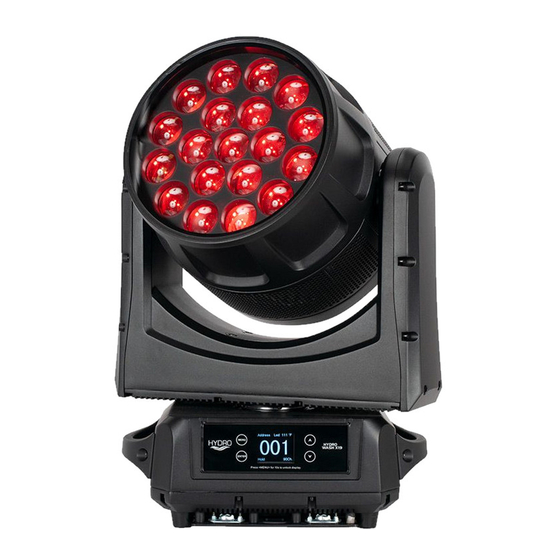
TECHNICAL SPECIFICATIONS Light Source: • 19x Osram 40W RGBW (4-IN-1) LEDs Features: • IP65 outdoor rated – protects fixture from dust, sand, moisture and liquid • Motorized Zoom: 6 ~ 40-degrees • Antenna Range: 98.42 ft (30m) Construction: • Color display with touch buttons •... -
Page 51: Fcc Statement
FCC STATEMENT This device complies with Part 15 of the FCC Rules. Operation is subject to the following two conditions: (1) this device may not cause harmful interference, and (2) this device must accept any interference received, including interference that may cause undesired operation. FCC RADIO FREQUENCY INTERFERENCE WARNINGS &...
Need help?
Do you have a question about the HYDRO WASH X19 and is the answer not in the manual?
Questions and answers