Table of Contents
Advertisement
Quick Links
Advertisement
Table of Contents

Related Manuals for ADJ HYDRO BEAM X12


Summary of Contents for ADJ HYDRO BEAM X12
- Page 1 HYDRO BEAM X12 User Instructions...
- Page 2 ©2022 ADJ Products, LLC all rights reserved. Information, specifications, diagrams, images, and instructions herein are subject to change without notice. ADJ Products, LLC logo and identifying product names and numbers herein are trademarks of ADJ Products, LLC. Copyright protection claimed includes all forms and matters of copyrightable materials and information now allowed by statutory or judicial law or hereinafter granted.
-
Page 3: Table Of Contents
C O N T E N T S General Information Limited Warranty (USA Only) IP65 Notice Safety Guidelines Overview Discharge Lamp Warning Lamp Installation Torque Settings for Screws Torque Screw Locations Color Wheel Gobo Wheel Fixture Installation Connections DMX Set Up DMX Addressing System Menu DMX Traits: Channel Functions &... -
Page 4: General Information
G E N E R A L I N F O R M AT I O N INTRODUCTION Please read and understand all instructions in this manual carefully and thoroughly before attempting to operate these products. These instructions contain important safety and use information. UNPACKING The products in this kit have been thoroughly tested and have been shipped in perfect operating condition. -
Page 5: Limited Warranty (Usa Only)
All shipping charges must be pre-paid. If the requested repairs or service (including parts replacement) are within the terms of this warranty, ADJ Products, LLC will pay return shipping charges only to a designated point within the United States. If the entire instrument is sent, it must be shipped in its original package. No accessories should be shipped with the product. -
Page 6: Ip65 Notice
I P 6 5 R AT E D An IP rated lighting fixture is one, which is commonly installed in outdoor environments and has been designed with an enclosure that effectively protects the ingress (entry) of external foreign objects such as dust and water. -
Page 7: Safety Guidelines
S A F E T Y G U I D E L I N E S FOR YOUR OWN PERSONAL SAFETY, PLEASE READ AND UNDERSTAND THIS MANUAL COMPLETELY BEFORE YOU ATTEMPT TO INSTALL OR OPERATE THIS UNIT! • THERE ARE NO USER SERVICEABLE PARTS INSIDE THIS UNIT. DO NOT ATTEMPT ANY REPAIRS YOURSELF;... - Page 8 To guarantee a smooth operation, it is important to follow all instructions and guidelines in this manual. ADJ Products, LLC is not responsible for injury and/or damages resulting from the misuse of this fixture due to the disregard of the information printed in this manual. Only qualified and/or certified personnel should perform installation of this fixture and only the original rigging parts included with this fixture should be used for installation.
- Page 9 S A F E T Y G U I D E L I N E S RISK GROUP 3 - RISK OF EXPOSURE TO ULTRAVIOLET UV RADIATION! FIXTURE EMITS HIGH INTENSITY WAVELENGTH OF ULTRAVIOLET UV LIGHT FROM THE UV COLOR FILTER. WEAR PROPER EYE AND SKIN PROTECTION.
- Page 10 LEDs. This issue is not specific only to ADJ lighting fixtures, it is a common issue with lighting fixtures from all manufacturers. Although there is no true way to fully prevent this issue from happening, the guidelines below can prevent any potential damage from occurring if followed.
-
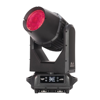
Page 11: Overview
OVERVIEW LENS SERVICE PORT UP Button IP65 Locking MENU Button IP65 Locking Power Connector 5-Pin DMX In/Out DOWN Button ENTER Button In/Out Fuse: T 10A Gore Valve LCD Menu Control Display... -
Page 12: Discharge Lamp Warning
DISCHARGE LAMP WARNING This fixture is fitted with a DISCHARGE LAMP, which is highly susceptible to damage if improperly handled. NEVER touch the lamp with your bare hands as the oil from your hands will shorten the life of the lamp. Also, NEVER move the fixture until the lamp has had ample time to cool. -
Page 13: Lamp Installation
LAMP INSTALLATION WARNING! LAMP REPLACEMENT SHOULD ONLY BE DONE BY A TRAINED TECHNICIAN. 2. Loosen the screws on the head of the fixture 1. Turn OFF power and allow approximately 15 and open the fixture head covers. Unplug the minutes for the fixture to cool down. fan and loosen the screw that secures the safety cable. -
Page 14: Torque Settings For Screws
T O R Q U E S E T T I N G S F O R S C R E W S A L L S C R E W S M U S T B E T I G H T E N E D W I T H A T O R Q U E D R I V E R . A l l s c r e w s a r e A l l e n H e a d s c r e w s . -
Page 15: Torque Screw Locations
T O R Q U E S C R E W S L O C AT I O N S... -
Page 16: Color Wheel
COLOR WHEEL... -
Page 17: Gobo Wheel
STATIC GOBO WHEEL... -
Page 18: Fixture Installation
FIXTURE INSTALLATION FLAMMABLE MATERIAL WARNING Keep fixture at least 7.9in. (0.2m) away from any flammable materials, decorations, pyrotechnics, etc. ELECTRICAL CONNECTIONS A qualified electrician should be used for all electrical connections and/or installations. MINIMUM DISTANCE TO OBJECTS/SURFACES MUST BE 40 FEET (12 METERS) MAXIMUM TEMPERATURE OF EXTERNAL SURFACE 167°F (75°C) DO NOT INSTALL THE FIXTURE IF YOU ARE NOT QUALIFIED TO DO SO! Fixture MUST be installed following all local, national, and country commercial electrical and construction... - Page 19 FIXTURE INSTALLATION NOTICE: The suitable environmental temperature for this lighting fixture is between -20˚ C to 40˚ C. Do not place this lighting fixture in an environment where the temperatures are under or above the temperatures stated above. This will allow the fixture to run at its best and help prolong the fixture life. Screw one clamp via a M12 screw and nut into the Omega holder.
- Page 20 CLAMP FAILS. AROUND CABLE CONNECTIONS. The Hydro Beam X12 is fully operational in three different mounting positions, hanging upside-down, mounted sideways on trussing, or set on a flat level surface. Be sure this fixture is kept at least 0.2m (7.9in.) away from any flammable materials (decoration etc.). Always use and install the supplied safety cable as a safety measure to prevent accidental damage and/or injury in the event the clamp fails (see next page).
-
Page 21: Connections
CONNECTIONS ENSURE ALL CONNECTIONS AND END CAPS ARE PROPERLY SEALED WITH A DIELECTRIC GREASE (AVAILABLE AT MOST ELECTRICAL SUPPLIERS) TO PREVENT WATER CORROSION AND/OR ELECTRICAL SHORT CIRCUIT. TO MAINTAIN IP65 RATING INTEGRITY AND PREVENT WATER FROM ENTERING THE FIXTURE, ALL UNUSED CONNECTION RUBBER CAPS MUST BE SEALED. -
Page 22: Dmx Set Up
XLR connector of the last unit in your daisy chain to terminate the line. Using a cable terminator (ADJ part number Z-DMX/T) will decrease the possibilities of erratic behavior. TO MAINTAIN IP65 RATING INTEGRITY AND PREVENT WATER FROM ENTERING THE FIXTURE, ALL UNUSED CONNECTION RUBBER CAPS MUST BE SEALED AND ONLY IP65 RATED POWER AND DATE CABLES MUST BE USED. -
Page 23: Dmx Addressing
DMX channels of each fixture. That means changing the settings of one channel will only affect the selected fixture. In the case of the Hydro Beam X12, when in 14 Channel mode, you should set the starting DMX address of the first unit to 1, the second unit to 15 (14 + 1), the third unit to 29 (15 + 14), and so on. -
Page 24: System Menu
SYSTEM MENU The fixture includes an easy to navigate system menu control panel display where all necessary settings and adjustments are made. Turn the unit on, press the MENU button to access the menu mode, and press the UP/DOWN button until the required function is displayed on the monitor. Select the function by pressing the ENTER button. - Page 25 SYSTEM MENU Menu Submenu Options Description DMX Address 001-512 DMX Addressing DMX Settings DMX Channel Mode Mode1(14)/Mode2(18) DMX Channel Mode Selection Hold Last / Blackout / Manual No DMX Status DMX Lost Status DMX: Yes / No Control via DMX WiFly: Yes / No Control via WiFly Select Signal...
- Page 26 SYSTEM MENU Menu Submenu Options Description Power On Time: XXXXXX Hours Total Running Time (Not Resettable) P On Time-R: XXXXXX Hours Total Running Time (Resettable) Fixture Life Time Reset P-On Time-R (Total Running P-On Time Reset: Pass Code = 050 Time) Lamp On Time - XXXXXX Hours Lamp On Time (Not Resettable)
- Page 27 SYSTEM MENU DMX Settings Select DMX Settings, and press the ENTER button to confirm. Use the UP/DOWN button to select DMX Address, DMX Channel Mode, or No DMX Status. DMX Address Select DMX Address, press the ENTER button to confirm. Use the UP/DOWN button to adjust the address from 001 to 499/495, press the ENTER button to store.
- Page 28 SYSTEM MENU WiFly Select WiFly, and press the ENTER button to confirm. Use the UP/DOWN button to select No or Yes and press the ENTER button to store. To select WiFly and DMX on, use the UP/DOWN button to select No or Yes and press the ENTER button to store. With the WiFly and DMX on, you can control the unit via wifly, and send a DMX signal via DMX cable to a nearby device that does not have WiFly capabilities.
- Page 29 Information, and use the UP/DOWN button to select Software. For the latest software, please contact ADJ Service Department (Email: support@adj.com, Phone (323) 582-2650). Once received, the software can be loaded to a USB Flash Drive (32 GB max., formatted to FAT32 if possible).
- Page 30 SYSTEM MENU Fixture Life Time Select Fixture Life Time, and press the ENTER button to confirm. Use the UP/DOWN button to select Power On Time, P‐On Time‐R, or P‐On Time Reset, and press the ENTER button to store. Press the MENU button to go back to the last menu, or let the unit idle 30 seconds to exit menu mode.
- Page 31 WIFLY There are many factors that affect and/or interrupt a wireless signal such as walls, glass, metal, objects, and people. Therefore, it is highly recommended to: • Install devices a minimum of 9.8 ft. (3m) above audiences and/or ground level •...
-
Page 32: Dmx Traits: Channel Functions & Values
DMX TRAITS: CHANNEL FUNCTIONS & VALUES (14/18 DMX Channels) 14 Channels 18 Channels Values Functions PAN MOVEMENT 8-BIT: 000-255 Pan Movement (0° - 540°) PAN FINE 16-BIT: 000-255 Fine Control of Pan Movement TILT MOVEMENT 8-BIT: 000-255 Tilt Movement (0° - 270°) TILT FINE 16-BIT: 000-255 Fine Control of Tilt Movement... - Page 33 14 Channels 18 Channels Values Functions Static Gobo 000-007 White 008-010 Gobo1 011-013 Gobo2 014-016 Gobo3 017-019 Gobo4 020-022 Gobo5 023-025 Gobo6 026-028 Gobo7 029-031 Gobo8 032-034 Gobo9 035-037 Gobo10 038-040 Gobo11 041-043 Gobo12 044-046 Gobo13 047-049 Gobo14 050-052 Gobo15 053-055 Gobo16 056-059...
- Page 34 14 Channels 18 Channels Values Functions Prism 2 Rotation 000-127 0-100% 128-189 Clockwise Rotation Fast to Slow 190-193 Stop 194-255 Counter-Clockwise Rotation Slow to Fast Strobe 000-031 Close 032-063 Open 064-095 Strobe From Slow to Fast 096-127 Open 128-159 Pulse Effect in Sequence 160-191 Open 192-223...
-
Page 35: Error Codes
ERROR CODES Print Error Message Description CPU-B Error CPU-B Error CPU-C Error CPU-C Error CPU-D Error CPU-D Error CPU-E Error CPU-E Error CPU-F Error CPU-F Error Pan Reset Error Pan: Reset Error Pan Encode Error Pan: Encoder Error Tilt Reset Error Tilt: Reset Error Tilt Encode Error Tilt: Encoder Error... - Page 36 CODES Print Error Message Description ArmFan2 Start Err Arm Fan 2 Cannot Start ArmFan2 Stop Err Arm Fan 2 Cannot Stop ArmFan2 Too Low Arm Fan 2 Speed Too Low ArmFan2 Too High Arm Fan 2 Speed Too High headFan1 Start Err Head Fan 1 Cannot Start HeadFan1 Stop Err Head Fan 1 Cannot Stop...
-
Page 37: Power Linking | Cleaning
MULTIPLE POWER LINKING With this feature you can connect the fixtures to one another using the power cable input and output sockets. NOTE: USE CAUTION WHEN POWER LINKING OTHER FIXTURES AS THE POWER CONSUMPTION OF OTHER MODEL FIXTURES MAY EXCEED THE MAX POWER OUTPUT ON THIS FIXTURE! CHECK SILK SCREEN FOR MAX AMPS. -
Page 38: Technical Specifications
S P E C I F I C AT I O N S Light Source: Control: • Configurable via RDM • Philips, 260W, MSD Platinum 12R LL Discharge • Controllable via DMX512 Lamp (6,000 hours) • 2 DMX Channel Modes: 14/18 Channels •... - Page 39 DIMENSIONS...
- Page 40 FCC STATEMENT This device complies with Part 15 of the FCC Rules. Operation is subject to the following two conditions: (1) this device may not cause harmful interference, and (2) this device must accept any interference received, including interference that may cause undesired operation. FCC RADIO FREQUENCY INTERFERENCE WARNINGS &...
Need help?
Do you have a question about the HYDRO BEAM X12 and is the answer not in the manual?
Questions and answers