Table of Contents
Advertisement
Quick Links
Advertisement
Table of Contents

Related Manuals for Peak PCAN-ExpressCard


Summary of Contents for Peak PCAN-ExpressCard
- Page 1 PCAN-ExpressCard ExpressCard to CAN Interface User Manual V2.1.0...
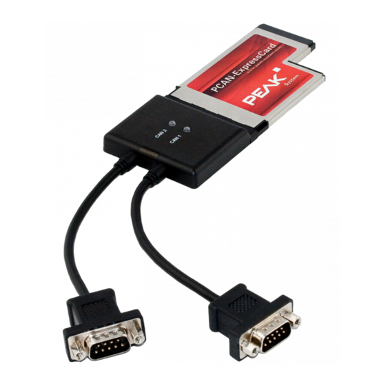
- Page 2 IPEH-003003 Channel galvanically decoupled isolation for CAN connections The cover picture shows the product PCAN-ExpressCard Dual Channel. Other product models have an identical form factor but vary in the number of CAN connectors according to the model. CANopen® and CiA® are registered community trade marks of CAN in Automation e.V.
-
Page 3: Table Of Contents
PCAN-ExpressCard – User Manual Contents Introduction Properties at a Glance Prerequisites for Operation Scope of Supply Installing the Software and the Card Connecting the CAN Bus D-Sub Connector Supplying External Devices via the CAN Connector Cabling 3.3.1 Termination 3.3.2 Example of a Connection 3.3.3... - Page 4 PCAN-ExpressCard – User Manual Technical Specifications PCAN-ExpressCard Appendix A CE Certificate Appendix B Dimension Drawing Appendix C Quick Reference...
-
Page 5: Introduction
PCAN-ExpressCard – User Manual Introduction The PCAN-ExpressCard provides one or two CAN channels for notebooks and computers with ExpressCard slots. Device drivers and programming interfaces exist for different operating systems, so programs can easily access a connected CAN bus. Tip: At the end of this manual (Appendix C) you can find a... -
Page 6: Prerequisites For Operation
PCAN-ExpressCard – User Manual Prerequisites for Operation ExpressCard slot in the computer, type ExpressCard/54 Operating system Windows 7/Vista/XP (32/64-bit) or Linux (32/64-bit) Scope of Supply PCAN-ExpressCard CAN interface Device drivers for Windows 7/Vista/XP (32/64-bit) and Linux (32/64-bit) PCAN-View CAN monitor for Windows... -
Page 7: Installing The Software And The Card
PCAN-ExpressCard – User Manual Installing the Software and the Card This chapter covers the software setup for the PCAN-ExpressCard under Windows and the installation in the computer. Setup the driver before connecting the PCAN-ExpressCard for the first time. Do the following to install the driver:... - Page 8 After the initialization process for the driver for the CAN interface is finished successfully an LED is on for each CAN connection of the PCAN-ExpressCard. Furthermore, you can find the entry “PCAN-ExpressCard” in the branch “CAN-Hardware” of the Windows Device Manager.
-
Page 9: Connecting The Can Bus
PCAN-ExpressCard – User Manual Connecting the CAN Bus D-Sub Connector A High-speed CAN bus (ISO 11898-2) is connected to the 9-pin D- Sub connector. The pin assignment corresponds to the specification CiA® 102. Figure 1: Pin assignment High-speed CAN Supplying External Devices via the CAN... -
Page 10: Cabling
CAN cables or peripheral systems (e.g. bus converters) to or from the PCAN-ExpressCard while it is de-energized (the card is not connected to the computer). Consider that some computers still supply the ExpressCard slot with power even when they are turned off (standby operation). -
Page 11: Maximum Bus Length
PCAN-ExpressCard – User Manual 3.3.3 Maximum Bus Length High-speed CAN networks may have bit rates of up to 1 Mbit/s, where all CAN nodes must be able to process messages simultaneously. The maximum bus length depends primarily on the bit rate. -
Page 12: Operation
PCAN-ExpressCard – User Manual Operation Status LED The PCAN-ExpressCard has a status LED for each existing CAN channel which may be in one of the following conditions: Status LED Meaning There's a connection to a driver of the operating system. -
Page 13: Using The Software
PCAN-ExpressCard – User Manual Using the Software This chapter covers the provided software PCAN-View and the programming interface PCAN-Basic. CAN Monitor PCAN-View for Windows PCAN-View for Windows is a simple CAN monitor for viewing, transmitting, and logging CAN messages. Figure 3: PCAN-View for Windows... - Page 14 PCAN-ExpressCard – User Manual If you haven't installed PCAN-View together with the device driver, you can start the program directly from the supplied CD. In the navigation program (Intro.exe) go to English > Tools, and under PCAN-View for Windows select the link Start.
-
Page 15: Receive/Transmit Tab
PCAN-ExpressCard – User Manual 5.1.1 Receive/Transmit Tab Figure 5: Receive/Transmit tab The Receive/Transmit tab is the main element of PCAN-View. It contains two lists, one for received messages and one for the transmit messages. Representation of CAN data is in hexadecimal format. - Page 16 PCAN-ExpressCard – User Manual Figure 6: Dialog box New transmit message Enter the ID and the data for the new CAN message. The field Cycle Time indicates if the message shall be transmitted manually or periodically. If you want to transmit the message periodically, you must enter a value greater than 0.
-
Page 17: Trace Tab
PCAN-ExpressCard – User Manual 5.1.2 Trace Tab Figure 7: Trace tab On the Trace tab the data tracer of PCAN-View is used for logging the communication on a CAN bus. During this process the CAN messages are cached in the working memory of the PC. Afterwards they can be saved to a file. -
Page 18: Pcan-Expresscard Tab
5.1.3 PCAN-ExpressCard Tab Figure 8: PCAN-ExpressCard tab On the PCAN-ExpressCard tab the 5-Volts supply on pin 1 of the D-Sub CAN connector is enabled or disabled. For the Dual Channel model the setting is valid for both CAN connectors simultaneously. -
Page 19: Status Bar
PCAN-ExpressCard – User Manual 5.1.4 Status Bar Figure 9: Example of the status bar The status bar shows information about the current CAN connection, about error counters (Overruns, QXmtFull), and shows error messages. You can find further information about the use of PCAN-View in the help which you can invoke in the program via the Help menu or with the F1 key. -
Page 20: Linking Own Programs With Pcan-Basic
On the provided CD you can find files of the programming interface PCAN-Basic in the directory branch Develop. This API provides basic functions for linking own programs to CAN interfaces by PEAK-System and can be used for the following operating systems: Windows 7/Vista/XP (32/64-bit) Windows CE 6.x (x86/ARMv4) The API is designed for cross-platform use. -
Page 21: Features Of Pcan-Basic
PCAN-ExpressCard – User Manual 5.2.1 Features of PCAN-Basic Multiple PEAK-System applications and a single one of your own can be used on a physical CAN channel at the same time A single DLL for all supported hardware types Use of up to 8 channels for each hardware unit (depending on... -
Page 22: Principle Description Of The Api
PCAN-ExpressCard – User Manual 5.2.2 Principle Description of the API The PCAN-Basic API is the interface between the user application and device driver. In Windows operating systems this is a DLL (Dynamic Link Library). The sequence of accessing the CAN interface is divided into three phases: 1. -
Page 23: Notes About The License
Notes about the License Device drivers, the interface DLL, and further files needed for linking are property of the PEAK-System Technik GmbH and may be used only in connection with a hardware component purchased from PEAK-System or one of its partners. If a CAN hardware component... - Page 24 PCAN-ExpressCard opto: Galvanic isolation up to 300 V (separate for each CAN channel) Supplying external PCAN-ExpressCard: D-Sub pin 1; 5 V, max. 100 mA devices PCAN-ExpressCard opto: D-Sub pin 1; 5 V, max. 50 mA Switched off at delivery Termination none Power supply Current consumption on 1.5-V pin...
- Page 25 PCAN-ExpressCard – User Manual Measures Size (without cables) 130 x 54 x 10 mm (L x W x D) See also dimension drawing in Appendix B on page 27 Weight Product model Single Channel: 60 g Dual Channel: 80 g...
- Page 26 PCAN-ExpressCard – User Manual Appendix A CE Certificate...
- Page 27 PCAN-ExpressCard – User Manual Appendix B Dimension Drawing Figure 11: Side view and top view of the PCAN-ExpressCard The figure does not show the actual size of the product.
- Page 28 Appendix C Quick Reference Software/Hardware Installation under Windows Before connecting the PCAN-ExpressCard to the computer set up the corresponding software package from the supplied CD (with administrator privileges). Afterwards insert the card into a ExpressCard slot of the computer. The card is recognized by Windows and the driver is initialized.
Need help?
Do you have a question about the PCAN-ExpressCard and is the answer not in the manual?
Questions and answers