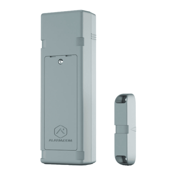
Alarm.Com Flex IO Installation Manual
Pull-apart
Hide thumbs
Also See for Flex IO:
- Installation manual (11 pages) ,
- Led patterns and troubleshooting (2 pages)
Advertisement
Flex IO - Pull-Apart Installation Guide
In addition to the standard contact functionality, the Flex IO can be integrated with third-party devices using the built-in
loop input. This guide covers the basics of setting up and mounting your Flex IO with a compatible pull-apart sensor.
Important: The Flex IO is a monitoring device that is not intended for life safety use cases. For more information about
use cases, see
Flex IO - Use
Equipment
In the box:
• Flex IO
• Magnet
• 4x AA 1.5V lithium batteries
• 300 kΩ resistor (optional)
Recommended tools and supplies (not included):
• Compatible pull-apart sensor (See
• 18-22 AWG wire
• Phillips head screwdriver
• Zip ties (if used for mounting; up to 3 recommended: 2 for Flex IO and 1 for magnet)
• #8 Phillips screws (if used for mounting; 4x)
• Paper clip (to press Flex IO diagnostic button; see
• ADC-FLEX-100-WRC Wire Retention Clip (optional)
Step 1: Determine location
Before installing your device, it is important to consider the following:
• Mounting options
• Loop Input wiring
• Cellular signal strength
https://answers.alarm.com/ADC/Partner/Installation_and_Troubleshooting/Cellular_Sensors/Flex_IO/Flex_IO_-_Pull-Apart_In...
Cases.
Which pull-apart sensors are recommended for the Flex
Cellular signal
strength)
IO?)
Updated: Sun, 11 Apr 2021 14:46:03 GMT
1
Advertisement
Table of Contents

Summary of Contents for Alarm.Com Flex IO
- Page 1 This guide covers the basics of setting up and mounting your Flex IO with a compatible pull-apart sensor. Important: The Flex IO is a monitoring device that is not intended for life safety use cases. For more information about...
-
Page 2: Mounting Options
Step 4: Mount the Flex • Using screws: Holes are located in the battery compartment. • Using zip ties: Use cutouts at the top and bottom of the device to make sure Flex IO is mounted flush to the installation surface. - Page 3 Step 2: Add the Flex IO to an Account 1. Log into the Partner Portal or MobileTech app. 2. Find the customer account. 3. In Cellular Sensors, verify at least one Flex IO has been added to their service package. 4. Click Equipment.
- Page 4 Step 3: Pull Apart Sensor Install Access Screw Terminals Remove the weatherproof gasket at the bottom of the Flex IO to access the screw terminals. Identify Necessary Screw Terminals • L-L: Both pins of the input loop • C: Common pin for relay control •...
- Page 5 Thread wires through the newly created holes (from the outside-facing side of the gasket inward) before securing them to the terminal block. This allows you to maintain the Flex IO's weatherproof seal. https://answers.alarm.com/ADC/Partner/Installation_and_Troubleshooting/Cellular_Sensors/Flex_IO/Flex_IO_-_Pull-Apart_In… Updated: Sun, 11 Apr 2021 14:46:03 GMT...
- Page 6 Ensure that the wired device performs as expected and that the waterproof gasket is inserted correctly. Attach the wire retention add-on by first clipping the front two sides and then pushing the clip in place. Secure on the back side of the https://answers.alarm.com/ADC/Partner/Installation_and_Troubleshooting/Cellular_Sensors/Flex_IO/Flex_IO_-_Pull-Apart_In… Updated: Sun, 11 Apr 2021 14:46:03 GMT...
- Page 7 Flex IO unit with the provided screw. Create a service loop with the installed wires and secure with a zip tie. Step 4: Mount the Flex IO The Flex IO can be mounted using either screws or zip ties. https://answers.alarm.com/ADC/Partner/Installation_and_Troubleshooting/Cellular_Sensors/Flex_IO/Flex_IO_-_Pull-Apart_In…...
- Page 8 • Zip ties should have a maximum width of 0.34 inches. UV resistant zip ties are recommended. • Use the zip tie grooves at the top and bottom of the Flex IO to ensure a secure installation. The magnet also has a zip tie groove across the center. https://answers.alarm.com/ADC/Partner/Installation_and_Troubleshooting/Cellular_Sensors/Flex_IO/Flex_IO_-_Pull-Apart_In…...
-
Page 9: Step 5: Insert The Batteries
Mounting tamper A mounting tamper is located on the back of the Flex IO. This tamper button must be fully pressed (until you hear a clicking sound) to avoid reporting a mounting tamper malfunction, as indicated by an alternating single Red and Yellow LED pattern. -
Page 10: Post-Installation Checklist
Flex IO - LED Patterns and Troubleshooting. Post-Installation Checklist • The Flex IO is installed flush to the mounting surface. If the mounting tamper is enabled, the tamper button on the back of the device should be pressed in. • LED is not blinking.


Need help?
Do you have a question about the Flex IO and is the answer not in the manual?
Questions and answers