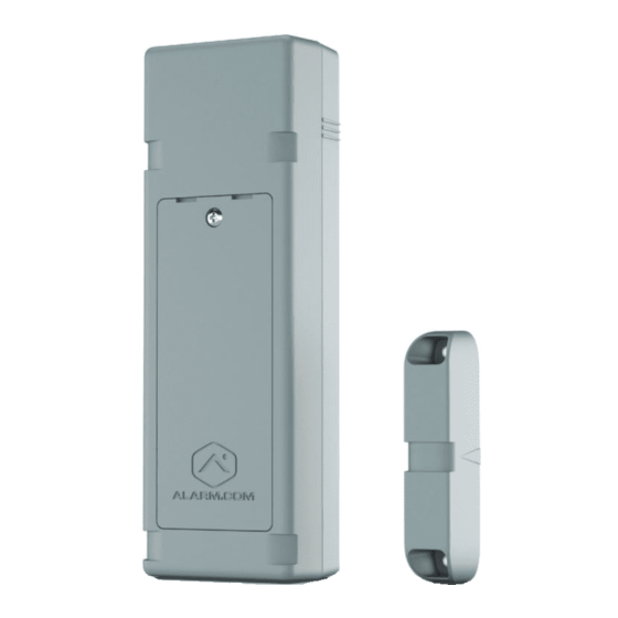
Alarm.Com Flex IO Installation Manual
Hide thumbs
Also See for Flex IO:
- Installation manual (10 pages) ,
- Led patterns and troubleshooting (2 pages)
Table of Contents
Advertisement
Quick Links
Advertisement
Table of Contents

Summary of Contents for Alarm.Com Flex IO
- Page 1 Flex IO Installation Guide ADC-FLEX-100...
-
Page 2: Table Of Contents
Table of contents Overview Equipment Step 1: Determine location Step 2: Add the Flex IO to an account Step 3: Mount the Flex IO Step 4: Insert the batteries Step 5: Confirm communication Post-installation checklist Specifications Regulatory information... -
Page 3: Overview
300 kΩ resistor (optional) LTE connectivity is available. Recommended tools and supplies Whether used with a backyard gate (not included) or a remote storage unit, the Flex IO • Phillips head screwdriver • Zip ties (up to 3 recommended: empowers users to keep an eye on 2 for Flex IO and 1 for magnet) •... -
Page 4: Step 1: Determine Location
• Using zip ties: Use cutouts at the top and bottom of the • Contact (reed switch) position device to make sure Flex IO is mounted flush to the • Mounting options install surface. • Input and output wiring •... - Page 5 DC power requirements Signal strength LED pattern In addition to battery power, the Flex IO can be powered with Pending a DC converter. DC power is required for relay installations due to increased power demands. 0 bars every 8 seconds DC power is optional for reed switch or input installations.
-
Page 6: Step 2: Add The Flex Io To An Account
After you have completed Step 1 and identified your Alarm.com Knowledge Base for more information. installation location (including power and wiring considerations), proceed with adding the device to The Flex IO can be mounted using either screws or zip ties. an account. Using screws ❶... -
Page 7: Step 4: Insert The Batteries
Mounting tamper A mounting tamper is located on the back of the Battery Flex IO. This tamper button must be fully pressed compartment (until you hear a clicking sound) to avoid reporting a mounting tamper malfunction, as indicated by an alternating single Red &... -
Page 8: Step 5: Confirm Communication
Step 5: Post-installation checklist Confirm communication ✓ The Flex IO is installed flush to the mounting surface. If the mounting tamper is enabled, the tamper button on the back Confirm device communication of the device should be pressed in. ✓... -
Page 9: Specifications
If this equipment • Flex IO can be powered by battery or external power does cause harmful interference to radio or television reception, which can be determined by turning the equipment off and on, the user is encouraged to try to •... - Page 10 Notes...
- Page 11 8281 Greensboro Drive Suite 100 200923 Tysons, VA 22102 © 2020 Alarm.com. All rights reserved.


Need help?
Do you have a question about the Flex IO and is the answer not in the manual?
Questions and answers