Advertisement
Quick Links
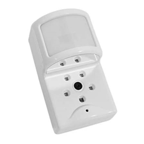
2GIG part number: 2GIG-IMAGE1
Alarm.com Image Sensor for 2GIG Go!Control
PRODUCT SUMMARY
The Image Sensor is a pet immune PIR (passive infrared) motion detector with a built-in
camera. The sensor is designed to capture images during alarm or non-alarm events.
Users can also initiate image capture on-demand to Peek-In on their property. Images are
stored locally and uploaded either automatically when motion is captured during alarm
events or manually when requested by the user. Once uploaded, images are available for
viewing on the Alarm.com Website or an Alarm.com Smart phone app. The sensor is
battery powered, all wireless and simple to install and operate. A system with a 2GIG Cell
Radio Module connected to an Alarm.com account with service plan subscription is
required. For additional information on product features, functionality and service plan
options, visit the Alarm.com Dealer Site (www.alarm.com/dealer).
Highlighted Features
Battery operated
Communicates wirelessly to the security control panel
35 feet by 40 feet detection coverage area
Configurable PIR sensitivity and pet immunity settings
Image: QVGA 320x240 pixels
Color Images (except in night vision)
Night vision image capture with infrared flash (black & white)
Tamper detection, walk test mode, supervision
HARDWARE COMPATIBILITY & REQUIREMENTS
Security Control Panel: 2GIG Go!Control with software 1.10 & up
Communication Module: 2GIG Cell Radio Module
Required Radio: 2GIG-XCVR2-345
Available Zones: One zone per Image Sensor installed (Up to 3 Image Sensors per
system)
HARDWARE INSTALLATION
IMPORTANT: For smoothest installation, learn in one Image Sensor at a time. Insert
batteries only after initiating learn mode at the panel. (See 4-f)
1. Create Alarm.com Customer Account
number, create an Alarm.com customer account on the Alarm.com Dealer Site
(www.alarm.com/dealer) with an Image Sensor capable service plan.
2. Verify module & XCVR2 radio installation- Ensure that the communication module
and XCVR2 radio are connected and installed properly inside the control panel.
3. Register Module and Test- Power up the panel and initiate a cell phone test to ensure
the communication module is properly installed and communicating with Alarm.com.
4. Enroll Sensor in Panel-
Enter the "system configuration" menu in the "installer toolbox".
a.
b.
Under Q1, select the RF sensor #. (Unused zone 01 to 48)
c.
Select the RF sensor type. (Recommended: 04- Interior Follower, 10-
Interior w/ Delay, 23- No Response Type)
d.
Select RF sensor equipment type. ((2) Motion)
e.
Select RF sensor equipment code. (9999 Alarm.com Image Sensor)
f.
Register the RF Sensor Serial Number: Power up the Image Sensor by
inserting the batteries. Click "learn" to initiate learn mode on the panel
and XCVR2 radio. Use a paper clip to hold the sensor's reset button until
the LED flashes rapidly for at least two seconds. It will take at least 10
seconds for this to occur. Note that a 1 second fast blink may occur
during the reset attempt. This just signals that the sensor is not enrolled
in a network. The reset button must be held for at least a full 10 seconds.
g.
Select RF sensor equipment age.
h.
Select RF sensor loop number. (Recommended: Loop 1)
i.
Select RF sensor dialer delay.
j.
Construct RF sensor voice descriptor. (Recommended shortcuts: 147-
Motion Detector, 120- IS)
k.
Select RF sensor reports. (Recommended: (1) Enabled)
l.
Select RF sensor supervised. (Recommended: (1) Enabled)
m.
Select RF sensor chime.
n.
Continue to edit next sensor or select skip, end and exit to save
changes.
1
Using the 2GIG Cell Radio Module serial
-
Copyright © 2014 Alarm.com. All rights reserved.
o.
Perform a cell phone test to ensure that the updated equipment list is
sent to Alarm.com.
The sensor is now learned into the panel. After enrollment, be sure to keep the sensor
and panel powered so the sensor can complete an initialization process with the
Alarm.com Network Operations Center. This process will take several minutes. Images
cannot be captured until initialization is complete. To verify that this process is
complete, enter the "Image Sensors" menu in the "installer toolbox". Select the Image
Sensor of interest and verify "rules status: complete".
5. Choose Sensor Location and Mount
a. Determine sensor mounting location based on installation scenario and criteria
noted in the "Installation Guidelines." For best image capture, the target capture
areas should be centered in the frame. (e.g. If customer wants to capture people
coming through door, the doorway should be centered in camera/PIR view.)
b. Verify RF communication prior to mounting- To verify that the Image Sensor
communicates with the control panel in its mounting location, enter "system test"
through the "installer toolbox" and trigger the Image Sensor.
c. Determine desired mounting angle for customer scenario; attach mounting arm to
sensor-back and re-attach sensor to sensor-back. The mounting arm attaches to the
back of the sensor enabling the sensor angle to vary based on the application. To
obtain the full 35' x 40' coverage area, mount the sensor at a 6˚
downward angle. This corresponds to a "teeth up" orientation of the mounting arm.
For most smaller areas in residential installations, mount the arm with the "teeth
down" for a deeper angle (18˚). Secure the back of the sensor to the mounting arm
with the provided screw. If the camera will be mounted perpendicular to the wall, the
mount the sensor without the mounting arm/bracket directly on the wall, at a 12°
angle.
Mounting Arm Orientation
Attach Mounting Arm to Sensor-Back
(Top: Teeth Up, Bottom: Teeth Down)
d. Choose applicable mounting bracket for customer scenario. The sensor
hardware packet contains 2 mounting brackets for different mounting scenarios.
Use the provided large screws and anchors to attach the bracket to the wall.
Flat Wall Mount
Mark location of bracket holes on mounting surface at a height of 8 feet for maximum
coverage area. (Leave at least 3 inches of clearance above the sensor to allow for
battery replacement without uninstalling the mounting bracket.)
e. Place sensor with arm on mounting bracket. Adjust the horizontal positioning of
the sensor to point towards the desired coverage area. To adjust positioning, lift the
mounting arm at least 1/3 of the way off the bracket and rotate the arm.
f. Secure the mounting arm location by sliding lock pin into the hole. Use the washer
and remaining small screw to secure the lock pin by screwing upwards through the
bottom of the hole in the mounting bracket. (Note: To make it easier to adjust
PIR/camera field of view in step 10, complete this step after horizontal sensor
positioning is finalized.)
6. Complete PIR Testing
Verify that PIR coverage adequately covers area by performing a walk test. (See "Pro-
gramming" section for more details.)
7. Test Image Capture
To conserve the customer's monthly image upload quota, automatic alarm uploads are
disabled for the first four hours after any new sensor (Image Sensor or other) is installed
into the system. Installers can verify sensor positioning and test image captures on
installed sensors on Alarm.com's Mobile Tech website (www.alarm.com/MobileTech),
Alarm.com part number: ADC-IS-100-GC
Installation Guide
Attach Sensor to
Sensor-Back
Corner Wall Mount
Rev 1.1
Advertisement

Related Manuals for Alarm.Com ADC-IS-100-GC


Summary of Contents for Alarm.Com ADC-IS-100-GC
- Page 1 Once uploaded, images are available for through the “installer toolbox” and trigger the Image Sensor. viewing on the Alarm.com Website or an Alarm.com Smart phone app. The sensor is battery powered, all wireless and simple to install and operate. A system with a 2GIG Cell c.
- Page 2 By default, the image sensor LED does not illuminate when activated by motion unless the sensor is in test mode. The LED can be enabled via the Alarm.com Dealer Website for each Image Sensor on a customer’s account. When enabled, the LED illuminates for 3 seconds upon motion activations (at most every 3 minutes while disarmed).
- Page 3 Enable Auto Uploads: During the first four hours after any sensor is enrolled onto the system, alarm images are not automatically uploaded to Alarm.com. Automatic FCC ID: YL6-143100ISGC IC: 9111A-143100ISGC uploads are automatically enabled after four hours. Enable uploads sooner from the Dealer Website.
Need help?
Do you have a question about the ADC-IS-100-GC and is the answer not in the manual?
Questions and answers