Table of Contents
Advertisement
Quick Links
Advertisement
Table of Contents

Related Manuals for amiad Spin Klin Nova Series


Summary of Contents for amiad Spin Klin Nova Series
- Page 1 Installation, Operation & Maintenance Instructions Spin Klin Nova Plus Spin Klin Nova Plus Dual Spin Klin Nova Plus Trio 910101-001091 / 01.2021 NOTE: This Document Contains Amiad Confidential Information. Copying and Distributing This Document are Strictly Prohibited.
- Page 2 Amiad or consult Amiad experts or its authorized representatives if you have any questions. Amiad Water Systems Ltd. D.N. Galil Elyon 1, 1233500, Israel Tel: 972 4 690 9500 | Fax: 972 4 814 1159 Email: info@amiad.com Installation &...
-
Page 3: Table Of Contents
Winterization…………..........................77 11.1. Filter Disassemble for Water Draining ..................79 11.2. Assembly After Water Draining ....................83 Bill of Materials………..........................88 Troubleshooting………......................... 100 Amiad Limited Warranty ........................102 Installation & Operation Manual Spin Klin™ Nova 910101-001009 | 01.2021... -
Page 4: Spin Klin Tm Nova Series
Spin Klin Nova Series 3'' Spin Klin Nova On-line 3'' Spin Klin Nova In-line 3'' Spin Klin Nova Angle 3'' Spin Klin Nova Reverse Angle Installation & Operation Manual Spin Klin™ Nova 910101-001009 | 01.2021... -
Page 5: Spin Klin Tm Nova Plus Series
Spin Klin Nova Plus Series 4'' Spin Klin Nova Plus On-line 4'' Spin Klin Nova Plus In-line 4'' Spin Klin Nova Plus Angle 4'' Spin Klin Nova Plus Reverse Angle Installation & Operation Manual Spin Klin™ Nova 910101-001009 | 01.2021... -
Page 6: Spin Klin Tm Nova Dual Series
Spin Klin Nova Dual Series 4" Spin Klin Nova Dual 6" Spin Klin Nova Plus Dual Installation & Operation Manual Spin Klin™ Nova 910101-001009 | 01.2021... -
Page 7: Spin Klin Tm Nova Trio Series
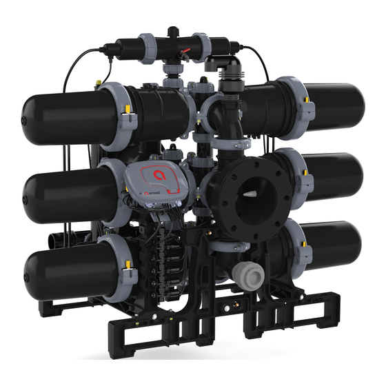
Spin Klin Nova Trio Series 6" Spin Klin Nova Trio 8" Spin Klin Nova Plus Trio Installation & Operation Manual Spin Klin™ Nova 910101-001009 | 01.2021... -
Page 8: Product Overview
Product Overview Single Installation & Operation Manual Spin Klin™ Nova 910101-001009 | 01.2021... - Page 9 Battery Installation & Operation Manual Spin Klin™ Nova 910101-001009 | 01.2021...
-
Page 10: Dimensional Drawings
Dimensional Drawings 3” Spin Klin Nova Single In-line 3” Spin Klin Nova Single On-line 3” Spin Klin Nova Single Angle Installation & Operation Manual Spin Klin™ Nova 910101-001009 | 01.2021... - Page 11 3” Spin Klin Nova Single Reverse Angle 3” Spin Klin Nova Plus Single In-line 3” Spin Klin Nova Plus Single On-line Installation & Operation Manual Spin Klin™ Nova 910101-001009 | 01.2021...
- Page 12 3” Spin Klin Nova Plus Single Angle 3” Spin Klin Nova Plus Single Reverse Angle 4” Spin Klin Nova Plus Single In-line Installation & Operation Manual Spin Klin™ Nova 910101-001009 | 01.2021...
- Page 13 4” Spin Klin Nova Plus Single On-line 4” Spin Klin Nova Plus Single Angle 4” Spin Klin Nova Plus Single Reverse Angle Installation & Operation Manual Spin Klin™ Nova 910101-001009 | 01.2021...
- Page 14 4" Spin Klin Nova Dual 6" Spin Klin Nova Plus Dual Installation & Operation Manual Spin Klin™ Nova 910101-001009 | 01.2021...
- Page 15 6" Spin Klin Nova Trio 8" Spin Klin Nova Plus Trio Installation & Operation Manual Spin Klin™ Nova 910101-001009 | 01.2021...
-
Page 16: Technical Specifications - Spin Klin Tm Nova
54 kg (118 lb) 115 kg (253 lb) 156 kg (344 lb) * Consult Amiad for optimum flow depending on filtration degree and water quality. ELECTRONIC CONTROL (ADI-P, SINGLE UNITS ONLY) ELECTRONIC CONTROL (ADI-X) 4 x AA type 1.5V batteries / External 7- 4 x D type 1.5V batteries /... -
Page 17: Technical Specifications - Spin Klin Tm Nova Plus
58 kg (129 lb) 127 kg (279 lb) 182 kg (401 lb) * Consult Amiad for optimum flow depending on filtration degree and water quality. ELECTRONIC CONTROL (ADI-P, SINGLE UNITS ONLY) ELECTRONIC CONTROL (ADI-X) 4 x AA type 1.5V batteries / External 7- 4 x D type 1.5V batteries /... -
Page 18: Introduction
• Always observe standard safety instructions and good engineering practices whilst working in the filter’s vicinity. • Use the filter only for its intended purpose as designed by Amiad Water Systems. Any misuse of the filter may lead to damage and may affect your warranty coverage. - Page 19 2.3. Safe Installation • Install the filter according to the detailed Installation Instructions provided with the filter by the manufacturer and according to the description given in this manual. • Make sure to leave enough clearance to enable easy access for safe maintenance operations.
- Page 20 2.5. Electricity • Electric wiring must be performed by an authorized electrician only, using standardized and approved components. • Install a lockable main power cut-off switch close to the control panel. • If due to site constraints, the control panel is installed without a clear line of vision to the filter, an additional lockable power disconnect cut-off switch should be installed near each filter unit.
- Page 21 2.9. Mechanical • Use only appropriate standard tools when working on the filter. • Always open and close valves slowly and gradually. • Remove grease and oily material residues to avoid slipping. • Before disconnecting the filter from the water supply, electricity and pneumatics and before releasing the filter’s residual pressure DO NOT: ▪...
-
Page 22: Spin Klin Tm Disc Technology
3. Spin Klin Disc Technology Amiad Water Systems uses a specially designed disc filtration technology. Thin, color-coded polypropylene/nylon discs are diagonally grooved on both sides to a specific micron size. A series of these discs are then stacked and compressed on a specially designed spine. When stacked, the groove on top runs opposite to the groove below, creating a filtration element with a statistically significant series of valleys and traps for solids. - Page 23 3.1. Spin Klin Spine – The Core of the Spin Klin Filtration System The Spin Klin discs are stacked on the Spin Klin spine. The discs are color-coded according to micron size and are assembled to suit the water filtration requirements. The spine assembly has a spring compression unit and an internal piston, which operate during alternate filtration or back-flush modes.
- Page 24 3.3. Nova Spin Klin Filtration Process 3.4. Nova Spin Klin Backwash Process Installation & Operation Manual Spin Klin™ Nova 910101-001009 | 01.2021...
-
Page 25: Unpacking Single
4. Unpacking Single 1. Remove the 12 lockers, rotate each one clockwise using your fingers in the designated grooves. 2. Open the top of the carton box and remove the filter. Note: Inside the carton box you will find: • Multifunction tool •... - Page 26 3. Place the Spin Klin Nova on a flat surface to extract the product from the supporting bridges. 4. Prior to installation, cut the plastic strips and lift the supporting bridge to release the product. Repeat this procedure on the other side to release the product completely. Installation &...
- Page 27 Note: In the On-line configuration, the command filter is disconnected during shipment Install the command filter Installation & Operation Manual Spin Klin™ Nova 910101-001009 | 01.2021...
-
Page 28: Unpacking Battery Filter
5. Unpacking Battery Filter 1. Remove the plastic shrink wrap that covers the filter. 2. Place the Spin Klin Nova on a flat surface in its final installation position. 3. Disconnect the three screws and separate the horizontal beams. Installation & Operation Manual Spin Klin™... - Page 29 4. Disconnect the vertical beams by releasing the bottom screws on each corner. Installation & Operation Manual Spin Klin™ Nova 910101-001009 | 01.2021...
- Page 30 Note: The command filter is disconnected during shipment. 5. Connect the command filter. Installation & Operation Manual Spin Klin™ Nova 910101-001009 | 01.2021...
- Page 31 Note: The air release valve is removed during shipment and needs to be reinstalled after the Spin Klin Nova is in its final position. 6. Remove the air release cap. Installation & Operation Manual Spin Klin™ Nova 910101-001009 | 01.2021...
- Page 32 7. Install the air release valve. Installation & Operation Manual Spin Klin™ Nova 910101-001009 | 01.2021...
-
Page 33: Spin Klin Tm Nova Multi-Tool
Spin Klin Nova Multi-tool A multifunction tool is provided with each Spin Klin™ Nova unit. See below various usage options: Finger filter servicing Universal nut Command filter cover nut System clamp joining bolts (M8 bolts – eq.13mm (½") spanner) Main clamp joining bolts (M10 bolts –... -
Page 34: Installation & Initial Operation
6. Installation & Initial Operation Prior to installation, flush the main line thoroughly to remove large objects that may damage the filter’s internal mechanism. 6.1. Inlet and Outlet Installation Connect the inlet and outlet ports according to the installation configurations described below, keep the service clearance from both sides, as shown: Note: Ensure that the direction of the flow is aligned with the arrows marked on the filter housing. - Page 35 Single On-line Battery Installation & Operation Manual Spin Klin™ Nova 910101-001009 | 01.2021...
- Page 36 6.2. Initial Operation For initial operation or operation after maintenance, follow these steps: 1. Retighten the system's universal nuts. 2. Open the outlet valve. 3. Open the inlet valve slowly. 4. Make sure there are no leaks in the filter. 5.
- Page 37 Note: Check that the back pressure in the drain manifold during flushing does not exceed 0.5 bar (7.5 psi). If it does, disconnect the accelerator’s drain tubes to ensure optimal performance. See instructions below. The filter is supplied with disconnected drain tubes. Single Battery Installation &...
- Page 38 6.3. Booster Drain Tubes Disconnection Single Disconnect the booster drain tubes and keep the tube ends open to the atmosphere. Plug in the two open connection ports with the supplied caps. Initiate a manual flush and listen for correct operation. Installation &...
- Page 39 Battery a. Disconnect the booster drain tubes and keep the tube ends open to the atmosphere. Plug in the two open connection ports with the supplied caps. Initiate a manual flush and listen for correct operation. Installation & Operation Manual Spin Klin™...
-
Page 40: Control Schematic
7. Control Schematic 7.1. ADI-P 7.2. ADI-X Installation & Operation Manual Spin Klin™ Nova 910101-001009 | 01.2021... -
Page 41: Maintenance Procedures
• Inspect the flushing valve seals, apply silicon grease periodically, and replace the seals if needed. • Visually inspect the discs, and in cases of non-washed sediments clean the discs according to Amiad's recommendations (see page 74). • Initiate one flushing cycle by manually operating the controller. Installation & Operation Manual Spin Klin™... -
Page 42: Filter Disassembly / Assembly
9. Filter Disassembly / Assembly A multifunction tool is provided with each Spin Klin™ Nova unit (see page 32). 9.1. Flushing Valve Disassembly Note: Before any maintenance procedure, please depressurize and empty the filter. 1. Close the inlet & outlet valves. 2. - Page 43 Battery Installation & Operation Manual Spin Klin™ Nova 910101-001009 | 01.2021...
- Page 44 5. Open the drain valve located at the bottom of the filter. 6. Open the command filter drain valve, in the On-line configuration the drain is located at the bottom. Installation & Operation Manual Spin Klin™ Nova 910101-001009 | 01.2021...
- Page 45 Note: For an overview of the location of the Supply, Drain and Command tubes, please refer to the diagram located on top of the booster cylinder cover Installation & Operation Manual Spin Klin™ Nova 910101-001009 | 01.2021...
- Page 46 7. Disconnect the tubes of the water supply (S), water drainage (D) & command tube (C) from the booster cylinder (the location of the connection may be different in other configurations). In-line On-line Installation & Operation Manual Spin Klin™ Nova 910101-001009 | 01.2021...
- Page 47 8. Unscrew the two bolts that join the system clamps using a 13mm (½") spanner and remove them. 9. Remove the clamps (you may need to use a flat screwdriver to separate them). Installation & Operation Manual Spin Klin™ Nova 910101-001009 | 01.2021...
- Page 48 10. Remove the booster cylinder by pulling it backwards. 11. For removing the valve assembly please, use both hands on the valve piston. Installation & Operation Manual Spin Klin™ Nova 910101-001009 | 01.2021...
- Page 49 12. Push the piston valve forward and pull it back rapidly, until released. Installation & Operation Manual Spin Klin™ Nova 910101-001009 | 01.2021...
- Page 50 13. Visually inspect the valve for damage, paying close attention to the seals. Caution: Do not insert your finger into the marked area. The valve is spring-loaded. 14. Apply silicon grease (catalog number: 760190-000127) at the specific locations as shown. Installation &...
-
Page 51: Flushing Valve Assembly
9.2. Flushing Valve Assembly 15. Insert the piston valve by pushing the marked area. Please make sure that the orientation grooves are aligned and the valve sits properly. 16. Place the booster cylinder on the flush valve. Installation & Operation Manual Spin Klin™... - Page 52 17. Place the system clamps. 18. Tighten the system clamps by using the two bolts with a 13mm (½") spanner. Installation & Operation Manual Spin Klin™ Nova 910101-001009 | 01.2021...
- Page 53 19. Connect the tubes of the water supply (S), water drainage (D) & command tube (C) to the booster cylinder. In-line On-line 20. Close drain valve and command filter drain valve. 21. Initiate a manual flushing procedure in order to test the system. Installation &...
-
Page 54: Main Cover And Filter Element
9.3. Main Cover and Filter Element 9.3.1. Disassembly Note: Before any maintenance procedure, please depressurize and empty the filter (see page 42). 1. Release the two hex nuts (17mm (1 ") spanner) that join the main clamps. Do not release them all the way, one side is acting as a hinge as shown. Installation &... - Page 55 2. Remove the connection from the slot using the connection as a lever to release the clamps by pulling it upwards. One side is acting as a hinge as shown. Installation & Operation Manual Spin Klin™ Nova 910101-001009 | 01.2021...
- Page 56 3. Push the bottom part of the main clamp downwards . Make sure to support the cover while doing this procedure. 4. Keep pushing until the bottom clamp is fully released. Installation & Operation Manual Spin Klin™ Nova 910101-001009 | 01.2021...
- Page 57 5. Remove the main clamps. 6. Remove the main cover. Note: Cover disassembly procedure is identical for Spin Klin Nova & Spin Klin Nova Plus Installation & Operation Manual Spin Klin™ Nova 910101-001009 | 01.2021...
- Page 58 Perform the following steps to extract the discs for the cleaning procedure. 7. Open the butterfly nut by rotating it counterclockwise. 8. Remove the butterfly nut. Installation & Operation Manual Spin Klin™ Nova 910101-001009 | 01.2021...
- Page 59 9. Remove the spine's cylinder on top of the spine. 10. Remove the discs. Pull out the disc holder (4" discs only) Installation & Operation Manual Spin Klin™ Nova 910101-001009 | 01.2021...
- Page 60 9.3.2. Assembly 1. For disc reassembly, please follow these steps according to your designated system: 2. Insert the discs onto the spine. 3. Place the spine cylinder on top of the spine. Installation & Operation Manual Spin Klin™ Nova 910101-001009 | 01.2021...
- Page 61 4. Place the butterfly nut on top of the cylinder. Installation & Operation Manual Spin Klin™ Nova 910101-001009 | 01.2021...
- Page 62 5. Tighten the butterfly nut clockwise, using the provided tool. 6. Reassemble the filter cover. Installation & Operation Manual Spin Klin™ Nova 910101-001009 | 01.2021...
- Page 63 7. Reassemble the main clamps. 8. Keep pushing the cover while placing the upper clamp and then place the bottom clamp. 9. Place the tie bar back to the slot. Installation & Operation Manual Spin Klin™ Nova 910101-001009 | 01.2021...
- Page 64 10. Tighten the two hex nuts (17mm (1 ") spanner) that join the main clamps. Installation & Operation Manual Spin Klin™ Nova 910101-001009 | 01.2021...
-
Page 65: Command Filter
9.4. Command Filter 9.4.1. Disassembly (both sides) Note: For an overview of the command filter cleaning procedure, please refer to the diagram located on the side of the command filter body. For each step you will find a designated number on the command filter body. - Page 66 2. Open the drain valve. 3. Release and open the cover nut (both sides). Installation & Operation Manual Spin Klin™ Nova 910101-001009 | 01.2021...
- Page 67 4. Extract the 1" spine. 5. Wash the discs thoroughly under running water (make sure the discs are separated and spinning during the cleaning process). Installation & Operation Manual Spin Klin™ Nova 910101-001009 | 01.2021...
- Page 68 9.4.2. Assembly (both sides) 1. Insert the disc spine into the command filter body. 2. Close the command filter and tighten the cover nuts. Installation & Operation Manual Spin Klin™ Nova 910101-001009 | 01.2021...
- Page 69 3. Close the drain valve. 4. Open the supply valve and initiate a manual flushing procedure in order to test the system. Installation & Operation Manual Spin Klin™ Nova 910101-001009 | 01.2021...
-
Page 70: Finger Filter
9.5. Finger Filter 9.5.1. Disassembly Note: Before any maintenance procedure, please depressurize and empty the filter (see page 42). 1. Disconnect the 8mm tube from the finger filter connection. 2. Release the finger filter counterclockwise (eq.30mm (1 ") spanner). Installation & Operation Manual Spin Klin™... - Page 71 3. Open the finger filter counterclockwise (eq.30mm (1 ") spanner). 4. Wash the filter thoroughly under running water. Installation & Operation Manual Spin Klin™ Nova 910101-001009 | 01.2021...
- Page 72 9.5.2. Assembly 1. Close the finger filter clockwise (eq.30mm (1 ") spanner). 2. Attach the finger filter clockwise (eq.30mm (1 ") spanner). 3. Reconnect the 8mm tube from the finger filter connection. Initiate a manual flushing procedure in order to test the system and open the inlet valve. Installation &...
-
Page 73: Disc Cleaning Procedure
10. Disc Cleaning Procedure 10.1. Seasonal Maintenance - Discs To guarantee thorough cleaning the following steps should be taken: Attention: When carrying out any of the following seasonal maintenance, service, or cleaning the discs – after backwashing the system and after closing the water inlet, make sure that there is no pressure in the system! 10.2. - Page 74 Attention! While working with chemicals protect yourself with the necessary safety equipment: • Safety glasses, gloves, protective clothing • Work in a well-ventilated area • Follow the manufacturer’s instructions • Store and discard chemicals according to local law. 10.4. Cleaning organic and biological deposits – with sodium hypochlorite (NaClO) 1.
- Page 75 1. Open the filter and remove the dirty discs. 2. Arrange the discs loosely on the plastic rope. 3. Prepare a 5% solution of hydrochloric acid (amount per disc set): Pour 25 liters (4”) or 10 liters (2”) of water into one of the large containers. Carefully add 5 (4”) or 2 (2”) liters of hydrochloric acid (30%) into the water.
- Page 76 10.8. Cleaning complex deposits If the composition of the deposit is not known, perform the following test: 1. Take 5 discs for the test. 2. Soak 2 discs in a 5% sodium hypochlorite solution. Preparation of the solution: Pour 1 cup of water into a small container, then add 1 cup of sodium hypochlorite (10% NaOCl).
-
Page 77: Winterization
11. Winterization In order to prevent the filter battery from becoming damaged during water freezing – drain all the water from the filter and the command filter and leave the drain valve open. To avoid damage or breakage, the filter, solenoid and command tubes must be drained prior to frost periods. - Page 78 3. Initiate an additional manual flush to release the pressure inside the filter. 4. Open the drain valve located at the bottom of the filter. Installation & Operation Manual Spin Klin™ Nova 910101-001009 | 01.2021...
-
Page 79: Filter Disassemble For Water Draining
11.1. Filter Disassembly for Water Draining 1. Open the command filter drain valve. 2. Disconnect the tubes of the water supply (S), water drainage (D) & command tube (C) from the booster cylinder. In-line Installation & Operation Manual Spin Klin™ Nova 910101-001009 | 01.2021... - Page 80 On-line Installation & Operation Manual Spin Klin™ Nova 910101-001009 | 01.2021...
- Page 81 3. Unscrew the two bolts that join the system clamps and remove them. 4. Remove the clamps (you may need to use a flat screwdriver to separate them). Installation & Operation Manual Spin Klin™ Nova 910101-001009 | 01.2021...
- Page 82 5. Remove the booster cylinder by pulling it backwards. Drain the booster cylinder from water residue. Ensure the filter is empty. Installation & Operation Manual Spin Klin™ Nova 910101-001009 | 01.2021...
-
Page 83: Assembly After Water Draining
11.2. Assembly After Water Draining 1. Reassemble the booster cylinder on the flush valve. 2. Reassemble the system clamps. Installation & Operation Manual Spin Klin™ Nova 910101-001009 | 01.2021... - Page 84 3. Tighten the system clamps by using the 2 bolts, with a 13mm (½") spanner. 4. Connect the tubes of the water supply (S), water drainage (D) & command tube (C) to the booster cylinder. In-line Installation & Operation Manual Spin Klin™...
- Page 85 On-line Installation & Operation Manual Spin Klin™ Nova 910101-001009 | 01.2021...
- Page 86 5. Disconnect the low & high sensor pressure 8mm connection from the ADI-P as shown, and leave unassembled until next season. Installation & Operation Manual Spin Klin™ Nova 910101-001009 | 01.2021...
- Page 87 6. Disconnect the tubes that supply water to the solenoid, and leave unassembled until next season. New Irrigation Season Prior to a new irrigation season, perform the following steps: 1. Connect the tubes that supply water to the solenoid and the booster. 2.
-
Page 88: Bill Of Materials
12. Bill of Materials 12.1. 3” Spin Klin Nova Single – Parts Schedule Installation & Operation Manual Spin Klin™ Nova 910101-001009 | 01.2021... - Page 89 12.2. 3” Spin Klin Nova Single – Parts List ITEM PART NUMBER DESCRIPTION QTY. 700190-006164 NOVA SINGLE ON-LINE FILTER ASSEMBLY 700190-005750 NOVA SINGLE IN-LINE FILTER ASSEMBLY 700190-006186 NOVA SINGLE ANGLE FILTER ASSEMBLY 700190-006187 NOVA SINGLE REVERSE ANGLE FILTER ASSEMBLY 710101-001492 NOVA DIVERTER RPA BLACK 700190-005740 NOVA DIVERTER CONNECTOR ASSEMBLY...
- Page 90 12.3. 3" / 4” Spin Klin Nova Plus Single – Parts Schedule Installation & Operation Manual Spin Klin™ Nova 910101-001009 | 01.2021...
- Page 91 12.4. 3" / 4” Spina Klin Nova Plus Single – Part List ITEM PARTNUMBER DESCRIPTION QTY. 700190-006164 NOVA SINGLE ON-LINE FILTER ASSEMBLY 700190-005750 NOVA SINGLE IN-LINE FILTER ASSEMBLY 700190-006186 NOVA SINGLE ANGLE FILTER ASSEMBLY 700190-006187 NOVA SINGLE REVERSE ANGLE FILTER ASSEMBLY 710101-001492 NOVA DIVERTER RPA BLACK 700190-005740...
- Page 92 12.5. 4” Spin Klin Nova Dual – Part Schedule Installation & Operation Manual Spin Klin™ Nova 910101-001009 | 01.2021...
- Page 93 12.6. 4” Spin Klin Nova Dual – Part List ITEM PART NUMBER DESCRIPTION QTY. 700104-001303 NOVA SINGLE IN-LINE RPA BLACK 130MIC 8MM TEFFEN 700190-005752 NOVA PLUG ASSEMBLY 700190-006330 HYDRAULIC SEAL+O-RING F/NOVA ASSY 700190-005749 NOVA SYSTEM CLAMP ASSEMBLY 760101-001441 HEX BOLT FULL THRD M8 50MM S/ST304 DIN933 760103-000096 FLAT WASHER M8 DIN125 S/ST316 710101-001676...
- Page 94 12.7. 6” Spin Klin Nova Plus Dual – Part Schedule Installation & Operation Manual Spin Klin™ Nova 910101-001009 | 01.2021...
- Page 95 12.8. 6” Spin Klin Nova Plus Dual – Part List ITEM PART NUMBER DESCRIPTION QTY. 700104-001304 NOVA PLUS SINGLE IN-LINE RPA BLACK 130MIC 8MM TEFFEN 700190-005752 NOVA PLUG ASSEMBLY 700190-006330 HYDRAULIC SEAL+O-RING F/NOVA ASSY 700190-005749 NOVA SYSTEM CLAMP ASSEMBLY 760101-001441 HEX BOLT FULL THRD M8 50MM S/ST304 DIN933 760103-000096 FLAT WASHER M8 DIN125 S/ST316...
- Page 96 12.9. 6” Spin Klin Nova Trio – Part Schedule Installation & Operation Manual Spin Klin™ Nova 910101-001009 | 01.2021...
- Page 97 12.10. 6” Spin Klin Nova Trio – Part List ITEM PART NUMBER DESCRIPTION QTY. 700104-001303 NOVA SINGLE IN-LINE RPA BLACK 130MIC 8MM TEFFEN 700190-005752 NOVA PLUG ASSEMBLY 700190-006330 HYDRAULIC SEAL+O-RING F/NOVA ASSY 700190-005749 NOVA SYSTEM CLAMP ASSEMBLY 760101-001441 HEX BOLT FULL THRD M8 50MM S/ST304 DIN933 760103-000096 FLAT WASHER M8 DIN125 S/ST316 710101-001676...
- Page 98 12.11. 8” Spin Klin Nova Plus Trio – Part Schedule Installation & Operation Manual Spin Klin™ Nova 910101-001009 | 01.2021...
- Page 99 12.12. 8” Spin Klin Nova Plus Trio – Part List ITEM PART NUMBER DESCRIPTION QTY. 700104-001304 NOVA PLUS SINGLE IN-LINE RPA BLACK 130MIC 8MM TEFFEN 700190-005752 NOVA PLUG ASSEMBLY 700190-006330 HYDRAULIC SEAL+O-RING F/NOVA ASSY 700190-005749 NOVA SYSTEM CLAMP ASSEMBLY 760101-001441 HEX BOLT FULL THRD M8 50MM S/ST304 DIN933 760103-000096 FLAT WASHER M8 DIN125 S/ST316...
-
Page 100: Troubleshooting
13. Troubleshooting No Backwash Symptom Possible causes Required actions Exceeded high flow rate drop down the Check the irrigation system flow rate. No hydraulic command transfer inlet pressure. Check the irrigation controller. Command filter is blocked. Manually clean the command filter. No electricity. - Page 101 Non-Stop Backwash Symptom Possible causes Required actions High flow rate exceeds planned Check the irrigation flow rate. irrigation Check the inlet / outlet and DP pressure during filtration mode. High DP remains after a backwash The flushing pressure is below the cycle required minimum.
-
Page 102: Amiad Limited Warranty
In no event shall Amiad be liable to the Buyer or any third party for any damages to property, or for any intangible or economic loss, including loss of profits, loss of customers or damage to reputation, for any damages, including... - Page 103 Manufacturer Amiad Water Systems Ltd. D.N. Galil Elyon 1, 1233500, Israel . Tel: +972 4690 9500 | Fax: +972 48141159 | Email: info@amiad.com European Authorised Representative for CE Obelis s.a. Bd Général Wahis 53, 1030 Brussels, Belgium. Tel: +(32) 2732 5954 | Fax: +(32) 27326003 | Email: mail@obelis.net...
Need help?
Do you have a question about the Spin Klin Nova Series and is the answer not in the manual?
Questions and answers