
Related Manuals for Avnet COM Express MSC C6B-SLH


Summary of Contents for Avnet COM Express MSC C6B-SLH
- Page 1 User Manual ® COM Express Basic Module MSC C6B-SLH Type 6 Pinout ® 6th Generation Intel Core Processor Family ® Intel 100 Series Chipset Rev. 1.1 2021-04-29...
- Page 2 Preface Copyright Notice EMC Rules Copyright © 2021 MSC Technologies GmbH. All rights This unit has to be installed in a shielded housing. If not reserved. installed in a properly shielded enclosure, and used in accordance with the instruction manual, this product may Copying of this document, and providing to others and the cause radio interference in which case the user may be use or communication of the contents thereof, is forbidden...
- Page 3 Product Support MSC engineers and technicians are committed to provide support to our customers whenever needed. Before contacting Avnet Integrated /MSC Technical Support please consult the respective pages on our web site at www.msc-technologies.eu for the latest documentation, drivers and software downloads.
-
Page 4: Table Of Contents
Contents 2.13.13 Power and System Management .......... 39 User Information ............. 8 2.13.14 General Purpose I/O ............. 40 About this Manual ......8 2.13.15 SPI Interface ................. 41 Symbols and Signal Words ......8 2.13.16 Module Type Definition ............42 2.13.17 Power and GND .............. - Page 5 6.8.9 View/Configure CPU Lock Options ........72 6.9.8 PCIe Root Port x ..............104 6.8.10 GT - Power Management Control .......... 72 6.9.9 SATA & Intel RST (RAID) Configuration ......106 6.8.11 PCH FW Configuration ............72 6.9.10 Software Feature Mask Selection ........107 6.8.12 AMT Configuration ..............
- Page 6 Revision History Rev. Date Description 2021-03-09 First Release 2021-04-29 Updated Bios chapter / legacy Raid not supported anymore ) MSC C6B-SLH MSC C6B-SLH User Manual 6 / 144...
- Page 7 Reference Documents ® COM Express Module Base Specification ® COM Express Revision 2.1 Last update: April 10 , 2012 PCI Local Bus Specification Rev. 2.1 PCI21.PDF Last update: June 1 , 1995 http://www.pcisig.com ATA/ATAPI-6 Specification d1410r3b.pdf http://www.t13.org/ Serial ATA Specification Serial ATA 1.0 gold.pdf Last update: August 29 , 2002 Rev.1.0...
-
Page 8: User Information
1 User Information 1.1 About this Manual This user’s guide provides information about the components, features All safety messages have a safety alert symbol and are structured as ® and connectors available on the MSC C6B-SLH COM Express follows: Compact Module. Danger, Warning or Caution Type of hazard 1.2 Symbols and Signal Words... -
Page 9: Intended Use
1.4 Intended Use 1.6 Electrostatic Sensitive Device The MSC high performance modules can be used in a variety of applications such as industrial control, robotics, HMI, transport and passenger information terminals. The MSC C6B-SLH module is based The MSC COM Express ®... -
Page 10: Technical Description
2 Technical Description 2.1 Introduction ® ® COM Express is an open specification from PICMG (PCI Industrial Currently four module sizes are defined in the COM Express Computer Manufacturer Group). It is a module concept to bring PCI Specification 2.1: the Mini Module, the Compact Module, the Basic ®... -
Page 11: Module Photos
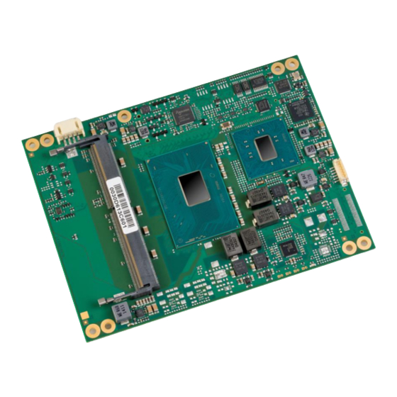
2.2 Module Photos Top side memory socket MAC address label Layout revision Board Identification number (BID) Fan connector Top Side View MSC C6B-SLH MSC C6B-SLH User Manual 11 / 144... - Page 12 Bottom side memory socket ® COM Express connector BIOS label Board identification label Bottom Side View MSC C6B-SLH MSC C6B-SLH User Manual 12 / 144...
-
Page 13: Key Features
2.3 Key Features ® ® The MSC C6B-SLH COM Express module is designed as a type 6 module according to COM Express Module Base Specification Revision 2.1. Key features include: ▪ ▪ Module size: 125 mm x 95 mm Four GPI pins ▪... -
Page 14: Block Diagram
2.4 Block Diagram MSC C6B-SLH MSC C6B-SLH User Manual 14 / 144... -
Page 15: Com Express ® Implementation
® 2.5 COM Express Implementation ® COM Express required and optional features for pin-out type 6 are summarized in the following table. The features identified as Minimum (Min.) shall be implemented by all modules. Features identified up to Maximum (Max) may be additionally implemented by a module. The column MSC C6B-SLH shows the features implemented by the MSC module. - Page 16 A-B General Purpose Outputs 4 / 4 A-B SMBus 1 / 1 A-B I 1 / 1 Standard mode up to 100kb/s, Fast Mode up to 400kb/s A-B Watchdog Timer 0 / 1 A-B Speaker Out 1 / 1 A-B External BIOS ROM support 0 / 2 A-B Reset Functions 1 / 1...
-
Page 17: Functional Units
2.6 Functional Units ® ® CPUs Intel Celeron G3902E, DC, 1.60GHz, 25W, 2ch DDR4 ® ® (SKL-H BGA 1440 Intel Celeron G3900E, DC, 1.90GHz, 35W, 2ch DDR4 package) ® ® Intel Core i3-6102E, DC, 1.90GHz, 3MB Intel Smart Cache, 25W, 2ch DDR4 ®... - Page 18 Digital Display Digital Display Interfaces (DDI) Ports DP 1.2 (4096x2304@60Hz) HDMI 1.4 (4096x2304@24Hz) DVI (1920x1200@60Hz) eDP 1.3 (4096x2304@60Hz) (Only available on modules with eDP mounting option.) ® Ethernet 10/100/1000Base-TX (Intel Ethernet Controller I219-LM) Serial Interface Two High Speed UARTs. (Functionality based on the 16550 industry standards. SIR mode, dual clock and external read enable signal for RAM wake up when using external RAMs is not supported.
-
Page 19: Power Supply
2.7 Power Supply ▪ +12V primary power supply input ▪ +5V standby Option, is not required for module operation. Voltage Input range Power Consumption If not present, customer must ensure that the supply voltages which are generated on the carrier board are switched off during suspend +12V +11.4V - 12.6 V states, so that no current from the carrier board’s signal lines can... - Page 20 Win 10 TAT! BurnInTest Module / CPU Win 10 Idle average peak ® ® C6B-SLH-102 (Intel Celeron G3900E, DC, 1.90GHz, 35W, 2ch DDR4, PCH: CM236) TAT package power 21W when workload set 5.3 W 23.4 W 24.2 W 14.1 W to 100% CPU-All 100% Gfx ®...
-
Page 21: Power Dissipation (Standby Modes)
2.8.2 Power Dissipation (Standby Modes) 1. System is shut down into “Suspend to RAM” (S3) by Windows 10 Enterprise 64-bit with Wake on LAN enabled. 2. System is shut down into “Soft Off” (S5) or “Suspend to Disk” (S4) by Windows 10 Enterprise 64-bit with Wake on LAN enabled. S4 / S5 Module / CPU Input Power... -
Page 22: System Memory
2.9 System Memory The MSC C6B-SLH CPU module provides two sockets for memory modules which have to meet the following demands: • 260 pin unbuffered DDR4 SO-DIMM. • 1.2V Supply Voltage • PC4-1866/2133, DDR4/ -RS SDRAM (DDR4 1866/2133) • Maximum module height: 1250mil = 31.75mm. •... -
Page 23: Mechanical Dimensions
2.10 Mechanical Dimensions 2.10.1 Basic Module ® There are two height options defined in the COM Express specification: 5mm and 8mm. The height option is defined by the connectors on the baseboard. MSC C6B-SLH MSC C6B-SLH User Manual 23 / 144... -
Page 24: Thermal Specifications
2.11 Thermal Specifications ® The cooling solution of a COM Express module is based on a heat- Humidity: 5 ... 95% (operating, non-condensing) spreader concept. 5 ... 95% (storage, non-condensing) A heat-spreader is a metal plate (typically aluminum) mounted on the top of the module. -
Page 25: Use Conditions
Certain Use Conditions may have an effect on the lifetime of the product. Please consult Avnet Integrated /MSC Technical Support if there are questions concerning specific Use Conditions when using the selected MSC module for the target application. -
Page 26: High Definition Audio
2.13.1 High Definition Audio Signal Signal Power Remark / PU/PD/SR Description Source / Target Type Level Rail Tolerance eSR = 22 Ω HDA_RST# CMOS 3.3V Sus Reset output to CODEC, active low. eSR = 22 Ω HDA_SYNC CMOS 3.3V Sus 48kHz fixed-rate, sample-synchronization signal to the CODEC(s), iPD = 20 KΩ... -
Page 27: Serial Ata
2.13.3 Serial ATA Signal Signal Power Remark / PU/PD/SR Description Source / Target Type Level Rail Tolerance SATA0_TX+ SATA 1.0V AC coupled Serial ATA Channel 0 transmit differential pair SATA0_TX- on module SATA0_RX+ SATA 1.0V AC coupled Serial ATA Channel 0 receive differential pair SATA0_RX- on module SATA1_TX+... -
Page 28: Pci Express Lanes
2.13.4 PCI Express Lanes Signal Signal Power Remark / PU/PD/SR Description Source / Target Type Level Rail Tolerance PCIE_TX[0:7]+ PCIe 1.0V AC coupled PCI Express Differential Transmit Pairs 0 through 7 PCIE_TX[0:7]- on module PCIE_RX[0:7]+ PCIe 1.0V AC coupled PCI Express Differential Receive Pairs 0 through 7 off module PCIE_RX[0:7]- PCIE_CLK_REF+... -
Page 29: Express Card Support
2.13.6 Express Card Support Signal Signal Power Remark / PU/PD Description Source / Target Type Level Rail Tolerance ePU = 10 KΩ EXCD[0]_CPPE# CMOS 3.3V 3.3V ExpressCard card request, active low ePU = 10 KΩ EXCD[1]_CPPE# CMOS 3.3V 3.3V ExpressCard card request, active low ePU = 10 KΩ... -
Page 30: Usb
2.13.7 USB Signal Signal Power Remark / PU/PD/SR Description Source / Type Level Rail Tolerance Target iPD = 14.25 kΩ - USB[0:7]+ 3.3V Sus 3.3V USB differential pairs, channels 0 through 7 24.8 kΩ USB[0:7]- iSR = 45 Ω ePU = 10 KΩ USB_0_1_OC# CMOS 3.3V Sus 3.3V USB channels 0 and 1 over-current sense. -
Page 31: Lpc Bus
2.13.8 LPC Bus Signal Signal Power Remark / PU/PD/SR Description Source / Target Type Level Rail Tolerance iPU = 15 – 40 KΩ LPC_AD[0:3] CMOS 3.3V 3.3V LPC multiplexed address, command and data bus LPC_FRAME# CMOS 3.3V LPC frame indicates the start of an LPC cycle LPC_DRQ0# CMOS 3.3V 3.3V... -
Page 32: Lvds / Edp
2.13.9 LVDS / eDP Signal Name LVDS Pin Number Signal Name eDP (Option) LVDS_A0+ eDP_TX2+ LVDS_A0- eDP_TX2- LVDS_A1+ eDP_TX1+ LVDS_A1- eDP_TX1- LVDS_A2+ eDP_TX0+ LVDS_A2- eDP_TX0- LVDS_A_CK+ eDP_TX3+ LVDS_A_CK- eDP_TX3- LVDS_VDD_EN eDP_VDD_EN LVDS_BKLT_EN eDP_BKLT_EN LVDS_BKLT_CTRL eDP_BKLT_CTRL LVDS_I2C_CK eDP_AUX+ LVDS_I2C_DAT eDP_AUX- RSVD eDP_HPD MSC C6B-SLH MSC C6B-SLH User Manual... - Page 33 2.13.9.1 LVDS Flat Panel (mounting option, only available on modules with LVDS mounting option) Signal Signal Power Remark / PU/PD/SR Description Source / Target Type Level Rail Tolerance LVDS_A[0:3]+ LVDS LVDS Channel A differential pairs ANX1122 LVDS_A[0:3]- LVDS_A_CK+ LVDS LVDS Channel A differential clock ANX1122 LVDS_A_CK- LVDS_B[0:3]+...
- Page 34 2.13.9.2 eDP (mounting option, only available on modules with eDP mounting option) Signal Signal Power Remark / PU/PD/SR Description Source / Target Type Level Rail Tolerance eDP_TX[0:3]+ PCIe AC coupled eDP differential pairs off module eDP_TX[0:3]- eDP_VDD_EN CMOS 3.3V 3.3V eDP power enable eDP_BKLT_EN CMOS 3.3V...
-
Page 35: Digital Display Interfaces
2.13.10 Digital Display Interfaces 2.13.10.1 Overview Type6 DDI Video Type Mapping Signal HDMI/DVI (TMDS Signaling) DDI1_PAIR0+/- DP1_LANE0+/- TMDS1_DATA2+/- DDI1_PAIR1+/- DP1_LANE1+/- TMDS1_DATA1+/- DDI1_PAIR2+/- DP1_LANE2+/- TMDS1_DATA0+/- DDI1 DDI1_PAIR3+/- DP1_LANE3+/- TMDS1_DATACLK+/- DDI1_HPD DP1_HPD HDMI1_HPD DDI1_CTRLCLK/DATA_AUX+/- DP1_AUX+/- HDMI1_CTRLCLK/DATA DDI1_DDC_AUX_SEL DDI2_PAIR0+/- DP2_LANE0+/- TMDS2_DATA2+/- DDI2_PAIR1+/- DP2_LANE1+/- TMDS2_DATA1+/- DDI2_PAIR2+/- DP2_LANE2+/-... - Page 36 2.13.10.2 DisplayPort Signal Signal Power Remark / PU/PD/SR Description Source / Target Type Level Rail Tolerance DP1_LANE[0:3]+ AC coupled DisplayPort Lane [0:3] differential pairs. DP1_LANE[0:3]- off module ePD = 100 KΩ DP1_AUX+ AC coupled DisplayPort Aux control channel differential pair on module ePU = 100 KΩ...
- Page 37 2.13.10.3 HDMI / DVI Signal Signal Power Remark / PU/PD/SR Description Source / Target Type Level Rail Tolerance TMDS1_DATA[0:2]+ TMDS AC coupled HDMI/DVI TMDS Data [0:3] output differential pairs. TMDS1_DATA[0:2]- off module TMDS1_DATACLK+ TMDS AC coupled HDMI/DVI TMDS Clock differential pairs. TMDS1_DATACLK- off module ePD = 100 KΩ...
-
Page 38: Serial Interface Signals
2.13.11 Serial Interface Signals Signal Signal Power Remark / PU/PD/SR Description Source / Type Level Rail Tolerance Target ePU = 49.9 KΩ SER0_TX CMOS 3.3V 12V, 3mA General purpose serial port transmitter (output) ePU = 49.9 KΩ SER0_RX CMOS 3.3V General purpose serial port receiver (input) ePU = 49.9 KΩ... -
Page 39: Power And System Management
2.13.13 Power and System Management Signal Signal Power Remark / PU/PD/SR Description Source / Target Type Level Rail Tolerance ePU = 10 KΩ PWRBTN# CMOS 3.3V Sus Power button to bring system out of or into Suspend states. Board Controller Reset button input. -
Page 40: General Purpose I/O
Signal Signal Power Remark / PU/PD/SR Description Source / Target Type Level Rail Tolerance ePU = 10 KΩ THRM# CMOS 3.3V 3.3V Input from off-module temperature sensor indicating an over-temp PCH, Board situation. Not supported. Controller ePU = 300 Ω THERMTRIP# CMOS 3.3V 3.3V,... -
Page 41: Spi Interface
2.13.15 SPI Interface Signal Signal Power Rem. PU/PD/SR Description Source / Type Level Rail / Tol. Target ePU = 10 KΩ Chip select for Carrier Board SPI - may be sourced from chipset SPI0 or SPI1. SPI_CS# CMOS 3.3V Sus 3.3V eSR = 33 Ω... -
Page 42: Module Type Definition
2.13.16 Module Type Definition Signal Signal Power Remark / PU/PD/SR Description Source / Target Type Level Rail Tolerance TYPE[0:2]# Type 6 module The TYPE pins indicate to the Carrier Board the Pin-out Type that is Carrier board logic implemented on the module. The pins are tied on the module to either ground (GND) or are no-connects (NC). -
Page 43: Power And Gnd
2.13.17 Power and GND Signal Signal Power Remark / PU/PD/SR Description Source / Target Type Level Rail Tolerance VCC_12V Power 12V (±5%) Primary power input: +12V (±5%) Voltage Regulators VCC_5V_SBY Power 5V (±5%) Standby power input: +5.0V (±5%) VCC3.3V SUS regulator If VCC5_SBY is used, all available VCC_5V_SBY pins on the connector(s) shall be used. -
Page 44: Pin List
2.14 Pin List MSC C6B-SLH Module (Type 6) Pin List: GND (FIXED) GND (FIXED) GND (FIXED) GND (FIXED) GBE0_MDI3- GBE0_ACT# GBE0_MDI3+ LPC_FRAME# USB_SSRX0- USB_SSTX0- GBE0_LINK100# LPC_AD0 USB_SSRX0+ USB_SSTX0+ GBE0_LINK1000# LPC_AD1 GBE0_MDI2- LPC_AD2 USB_SSRX1- USB_SSTX1- GBE0_MDI2+ LPC_AD3 USB_SSRX1+ USB_SSTX1+ GBE0_LINK# LPC_DRQ0# GBE0_MDI1- LPC_DRQ1# USB_SSRX2-... - Page 45 SATA0_RX- SATA1_RX- PCIE_RX6- PCIE_TX6- GND (FIXED) GND (FIXED) GND (FIXED) GND (FIXED) SATA2_TX+ SATA3_TX+ PCIE_RX7+ PCIE_TX7+ SATA2_TX- SATA3_TX- PCIE_RX7- PCIE_TX7- SUS_S5# PWR_OK DDI1_HPD RSVD SATA2_RX+ SATA3_RX+ DDI1_PAIR4+ RSVD SATA2_RX- SATA3_RX- DDI1_PAIR4- DDI1_PAIR0+ BATLOW# RSVD DDI1_PAIR0- (S)ATA_ACT# AC/HDA_SDIN2 RSVD RSVD AC/HDA_SYNC AC/HDA_SDIN1 DDI1_PAIR5+ DDI1_PAIR1+...
- Page 46 GND (FIXED) GND (FIXED) GND (FIXED) GND (FIXED) USB2- USB3- DDI3_PAIR1+ DDI2_PAIR1+ USB2+ USB3+ DDI3_PAIR1- DDI2_PAIR1- USB_2_3_OC# USB_0_1_OC# DDI3_HPD DDI2_HPD USB0- USB1- RSVD RSVD USB0+ USB1+ DDI3_PAIR2+ DDI2_PAIR2+ VCC_RTC EXCD1_PERST# DDI3_PAIR2- DDI2_PAIR2- EXCD0_PERST# EXCD1_CPPE# RSVD RSVD EXCD0_CPPE# SYS_RESET# DDI3_PAIR3+ DDI2_PAIR3+ LPC_SERIRQ CB_RESET# DDI3_PAIR3-...
- Page 47 PCIE_TX2- PCIE_RX2- PEG_RX3- PEG_TX3- GPI1 GPO3 RSVD RSVD PCIE_TX1+ PCIE_RX1+ RSVD RSVD PCIE_TX1- PCIE_RX1- PEG_RX4+ PEG_TX4+ WAKE0# PEG_RX4- PEG_TX4- GPI2 WAKE1# RSVD PCIE_TX0+ PCIE_RX0+ PEG_RX5+ PEG_TX5+ PCIE_TX0- PCIE_RX0- PEG_RX5- PEG_TX5- GND (FIXED) GND (FIXED) GND (FIXED) GND (FIXED) LVDS_A0+ LVDS_B0+ PEG_RX6+ PEG_TX6+ LVDS_A0-...
- Page 48 LVDS_I2C_CK LVDS_BKLT_CTRL RSVD RSVD LVDS_I2C_DAT VCC_5V_SBY GPI3 VCC_5V_SBY PEG_RX10+ PEG_TX10+ RSVD VCC_5V_SBY PEG_RX10- PEG_TX10- eDP_HPD VCC_5V_SBY PCIE0_CK_REF+ BIOS_DIS1# PEG_RX11+ PEG_TX11+ PCIE0_CK_REF- VGA_RED PEG_RX11- PEG_TX11- GND (FIXED) GND (FIXED) GND (FIXED) GND (FIXED) SPI_POWER VGA_GRN PEG_RX12+ PEG_TX12+ SPI_MISO VGA_BLU PEG_RX12- PEG_TX12- GPO0 VGA_HSYNC SPI_CLK...
- Page 49 A104 VCC_12V B104 VCC_12V C104 VCC_12V D104 VCC_12V A105 VCC_12V B105 VCC_12V C105 VCC_12V D105 VCC_12V A106 VCC_12V B106 VCC_12V C106 VCC_12V D106 VCC_12V A107 VCC_12V B107 VCC_12V C107 VCC_12V D107 VCC_12V A108 VCC_12V B108 VCC_12V C108 VCC_12V D108 VCC_12V A109 VCC_12V B109...
-
Page 50: Jumpers And Connectors
3 Jumpers and Connectors 3.1 Jumpers There are three jumpers available on the module: BIOS Default: By shorting the pins of this jumper during boot, the values of the BIOS setup will be reset to default values. BIOS Recovery: By shorting the pins of this jumper during boot the system is forced into crisis recovery mode. -
Page 51: Fan Connector
3.2 Fan Connector 4 Watchdog The connector of the fan is located at top side of the CPU module: The following connector type is used: • JST S4B-PH-SM4-TB The C6B-SLH board has a watchdog function implemented by an The fan itself should be equipped with a JST PHR-4 connector and one embedded controller. -
Page 52: System Resources
5 System Resources 5.1 PCI IRQ Routing Interrupts of Controller Dev / PIRQ 0 PIRQ 1 PIRQ 2 PIRQ 3 PIRQ 4 PIRQ 5 PIRQ 6 PIRQ 7 Slot Number Bus # (or Onboard Device) Function (INT A) (INT B) (INT C) (INT D) (INT E) -
Page 53: Smb Address Map
NOTE: x means that this Interrupt is used by an internal chipset ® device, e.g. the Intel Graphics Device is connected to PIRQ4 and uses NOTE: The assignment of the Chipset Pcie Lanes to the Com Interrupt A. ®... -
Page 54: Bios
6 BIOS 6.1 Introduction This guide describes the AMI Aptio Setup Startup screen and contains information on how to access Aptio setup to modify the settings which control AMI pre-OS (operating system) functions. 6.2 Startup Screen Overview The AMI Aptio Startup screen is a graphical user interface (GUI) that is included in AMI Aptio products. The default bios behavior is to show an informational text screen during bios POST phase, but the graphical boot screen can be enabled in the bios setup. -
Page 55: Bios Menu Structure
6.6 BIOS Menu Structure The BIOS Menu is structured in the following way: Main Advanced Chipset Security Boot Save & Exit MSC Board Info CPU Configuration System Agent (SA) Administrator Password Boot Configuration Save Options Configuration Boot Device Priorities Boot Override Hardware Monitoring Power &... -
Page 56: Menu Bar
6.6.1 Menu Bar The Menu Bar at the top of the window lists these selections: Menu Items Description Main Use this menu for basic system information. Use this menu to set the Advanced Features available on your system’s chipset. Advanced Chipset Use this menu to set Chipset Features. -
Page 57: Legend Bar
6.6.2 Legend Bar Use the keys listed in the legend bar on the right side of the screen to make your selections, or to exit the current menu. The following table describes the legend keys and their alternates: Function Exit submenu / Exit Setup utility without saving Left and right arrow keys Select Screen Up and down arrow keys... -
Page 58: Main Menu
6.7 Main Menu You can make the following selections on the Main Menu itself. Use the sub menus for other selections. Feature Options Description Bios Vendor Informative Shows the Bios Vendor Core Version Informative Shows the Aptio Core Version Compliancy Informative Shows the UEFI Compliance Version Project Version... -
Page 59: Msc Board Info
6.7.1 MSC Board Info Feature Options Description Manufacturer MSC Technologies GmbH Board Name Informative Shows the board name Board Revision Informative Shows the board revision Bios Version Informative Shows the bios version Serial Number Informative Shows the boards serial number Boot Counter Informative Shows the amount of boots... -
Page 60: Hardware Monitoring Measurement
6.7.2 Hardware Monitoring Measurement NOTE The value shown in the BIOS and EAPI for the temperatures, is the temperature read by the Board controller from a sensor mounted on the board. Feature Options Description CPU Temperature Informative Shows CPU Temperature Also supported in EAPI ... -
Page 61: System Information
6.7.3 System Information Feature Options Description Processor Information Informative Shows Processor Information IGFX VBIOS Version Informative Shows IGFX VBIOS Version PCH Information Informative Shows PCH Information ME FW Version Informative Shows ME FW Version ME Firmware SKU Informative Shows ME Firmware SKU SPI Clock Frequency Informative Shows SPI Clock Frequency... -
Page 62: Advanced Menu
6.8 Advanced Menu Feature Options Description CPU Configuration Submenu CPU Configuration Power & Performance Submenu Power & Performance Thermal Configuration Submenu Thermal Configuration Intel ICC Submenu Intel ICC Trusted Computing Submenu Trusted Computing ACPI Settings Submenu ACPI Settings SMART Settings Submenu SMART Settings Serial Port Console... -
Page 63: Cpu Configuration
6.8.1 CPU Configuration NOTE : Depending on type of CPU setup options can vary Feature Options Description SW Guard Extensions (SGX) Software Controlled, Enable/Disable Software Guard Extensions (SGX Enabled, Disabled Select Owner EPOCH input No Change in Owner There are three Owner EPOCH modes (Each EPOCH is 64bit): no type EPOCHs, Change to new change in owner epoch, change to new random owner epoch and... -
Page 64: Cpu Smm Enancement
Feature Options Description MachineCheck Enabled, Disabled Enable/Disable Machine Check MonitorMWait Enabled, Disabled Enable/Disable MonitorMWait Intel Trusted Execution Enabled, Disabled Enables utilization of additional hardware capabilities provided by Technology Intel (R) Trusted Execution Technology. Changes require a full power cycle to take effect. Reset AUX Content No, Yes Reset TPM Aux content. -
Page 65: Power & Performance
Feature Options Description SMM Use Block Indication Enabled, Disabled Enable/Disable usage of SMM_BLOCKED MSR for MP sync in SMI SMM Use SMM en-US Enabled, Disabled Enable/Disable usage of SMM_ENABLE MSR for MP sync in SMI Indication 6.8.3 Power & Performance Feature Options Description... - Page 66 Feature Options Description If native OS support is not available, BIOS will try to enable it using the OOB interface, if the interface is supported Turbo Mode Enabled, Disabled Enable/Disable processor Turbo Mode (requires EMTTM enabled too). AUTO means enabled, unless max turbo ratio is bigger than 16 - SKL A0 W/A View / Configure Turbo Submenu...
-
Page 67: View/Configure Turbo Options
Feature Options Description C10 ) Latency ( also for each C- 0-1023 Interrupt Response Time Limit value- bits [9:0], Enter 0-1023 state selectable ) Thermal Monitor Enabled, Disabled Enable/Disable Thermal Monitor Interrupt Redirection Mode Fixed Priority, Round robin, Interrupt Redirection Mode Select for Logical Interrupts Selection Hash vector, PAIR with Fixed Priority, PAIR with Round... - Page 68 Feature Options Description Limit 1 Time Window. Power Limit 1 Value Power Limit 1 in Milli Watts. BIOS will round to the nearest 1/8W when programming. 0 = no custom override. For 12.50W, enter 12500. Overclocking SKU: Value must be between Max and Min Power Limits (specified by PACKAGE_POWER_SKU_MSR).
-
Page 69: Tdp Configurations
6.8.6 TDP Configurations Feature Options Description Configurable TDP Boot Nominal, Down, Deactivate Configurable TDP Mode as Nominal/Up/Down/Deactivate TDP selection. Deactivate option will set MSR to Nominal and MMIO to Zero. Configurable TDP Lock Enabled, Disabled Configurable TDP Mode Lock sets the Lock bits on TURBO_ACTIVATION_RATIO and CONFIG_TDP_CONTROL. - Page 70 Feature Options Description Power Limit 2 Value Power Limit 2 value in Milli Watts. BIOS will round to the nearest 1/8W when programming. 0 = no custom override. For 12.50W, enter 12500. Processor applies control policies such that the package power does not exceed this limit. Power Limit 1 Time Window Value Power Limit 1 Time Window value in seconds.
-
Page 71: Custom P-State Table
6.8.7 Custom P-state Table Feature Options Description Number of P-States Value Sets the number of custom P-states. At least 2 states must be present. Max P-State Ratio Value Maximum P-state ratio to use in the custom P-state table. P-State Ratio Value P-state ratio for the given state in the custom P-state table. -
Page 72: View/Configure Cpu Lock Options
6.8.9 View/Configure CPU Lock Options Feature Options Description CFG Lock Enabled, Disabled Confgire MSR 0xE2[15], CFG Lock bit Overclocking Lock Enabled, Disabled Enable/Disable Overclocking Lock (BIT 20) in FLEX_RATIO(194) 6.8.10 GT - Power Management Control Feature Options Description RC6(Render Standby) Maximum GT frequency Check to enable render standby support. -
Page 73: Amt Configuration
Feature Options Description JHI Support Enabled, Disabled Enable/Disable Intel(R) DAL Host Interface Service (JHI) Core Bios Done Message Enabled, Disabled Enable/Disable Core Bios Done message sent to ME Firmware Update Submenu Firmware Update Configuration Configuration 6.8.12 AMT Configuration Feature Options Description ASF Support Enabled, Disabled... -
Page 74: Asf Configuration
Feature Options Description Setup. CIRA Timeout Value OEM defined timeout for MPS connection to be established. 0 - use the default timeout value of 60 seconds. 255 - MEBx waits until the connection succeeds 6.8.14 ASF Configuration Feature Options Description PET Progress Enabled, Disabled Enable/Disable PET Events Progress to receive PET Events. -
Page 75: Oem Flags Settings
6.8.16 OEM Flags Settings Feature Options Description MEBx hotkey Pressed Enabled, Disabled OEMFLag Bit 1: Enable automatic MEBx hotkey press. MEBx Selection Screen Enabled, Disabled OEMFLag Bit 2: Enable MEBx selection screen with 2 options: Press 1 to enter ME Configuration Screens Press 2 to initiate a remote connection ... -
Page 76: Mebx Resolution Settings
6.8.17 MEBx Resolution Settings Feature Options Description Non-UI Mode Resolution Auto, 80x25, 100x31 Resolution for non-UI text mode. UI Mode Resolution Auto, 80x25, 100x31 Resolution for UI text mode. Graphics Mode Resolution Auto, 640x480, 800x600, Resolution for graphics mode. 1024x768 6.8.18 Firmware Update Configuration Feature Options... -
Page 77: Cpu Thermal Configuration
6.8.20 CPU Thermal Configuration Feature Options Description DTS SMM Enabled, Disabled Disabled: ACPI thermal management uses EC reported temperature values. Enabled: ACPI thermal management uses DTS SMM mechanism to obtain CPU temperature values. Out of Spec: ACPI Thermal Management uses EC reported temperature values and DTS SMM is used to handle Out of Spec condition. -
Page 78: Platform Thermal Configuration
Feature Options Description PECI Reset Enabled, Disabled Enable/Disable PECI Reset during Sx. Enabling will trigger a PECI Reset during boot to resolve rare Sx PECI issue. Via pcode mailbox command 0x36. Default is disabled. PECI C10 Reset Enabled, Disabled Enable/Disable PECI C10 Reset command. Enables a mailbox command to resolve rare PECI related C10 issues. -
Page 79: Intel Rapid Storage Technology
Feature Options Description ICC Locks after EOP Default, All Locked, All Specifies the ICC registers that can be written after end-of-post. Unlocked Default - Dynamic registers for runtime clock adjustments are left writeable. All Locked - No clock register adjustments allowed after EOP. -
Page 80: Acpi Settings
6.8.25 ACPI Settings Feature Options Description Native PCIE Enable Enabled, Disabled PCI Express Native Support Enable/Disable. Hibernation Support Enabled, Disabled Enables or Disables System ability to Hibernate (OS/S4 Sleep State). This option may not be effective with some operating systems. ACPI Sleep State Disabled, S3 ( Suspend to Select the highest ACPI sleep state the system will enter when the... -
Page 81: Console Redirection Submenu
Feature Options Description Console Redirection settings Submenu The settings specify how the host computer and the remote Com 0-6 computer (which the user is using) will exchange data. Both computers should have the same or compatible settings. Legacy Console Redirection Submenu Legacy Console Redirection Settings Serial Port for Out-of Band... -
Page 82: Intel Txt Information
Feature Options Description Communication with slow devices may require more than 1 stop bit. Flow Control None, Hardware RTS/CTS, Flow control can prevent data loss from buffer overflow. When sending data, if the receiving buffers are full, a 'stop' signal can be sent to stop the data flow. -
Page 83: Ami Graphic Output Protocol Policy
Feature Options Description Error Code Informative This holds the Intel TXT shutdown error code. Class Code Informative Error code[9:4] Major Code Informative Error code[14:10] Minor Code Informative Error code[24:16] 6.8.30 AMI Graphic Output Protocol Policy Feature Options Description Output Select EDP1, DP1, DP 2, LFP , DVI, Select Output Interface during Boot HDMI 1, HDMI 2... -
Page 84: Csm Configuration
Feature Options Description IP6 Configuration Policy Atomatoc, Manual Set IP6 Configuration Policy PXE boot wait time Value Wait time to press ESC key to abort the PXE boot Media detect count Value Number of times presence of media will be checked 6.8.32 CSM Configuration Feature Options... -
Page 85: Nvme Configuration
6.8.33 NVMe Configuration Feature Options Description NVMe Devices Informative Shows NVMe Devices if installed 6.8.34 SDIO Configuration Feature Options Description SDIO Access Mode Auto, ADMA, SDMA, PIO Auto Option: Access SD device in DMA mode if controller supports it,otherwise in PIO mode.DMA Option: Access SD device in DMA mode.PIO Option: Access SD device in PIO mode. - Page 86 Feature Options Description EHCI Hand-off Enabled, Disabled This is a workaround for OSes without EHCI hand-off support. The EHCI ownership change should be claimed by EHCI driver. USB Mass Storage Driver Enabled, Disabled Enable/Disable USB Mass Storage Driver Support Support Port 60/64 Emulation Enabled, Disabled Enables I/O port 60h/64h emulation support.
-
Page 87: Sio Wb 627 / Sio Smsc311X Configuration
6.8.36 SIO WB 627 / SIO SMSC311X Configuration Feature Options Description COM A-D Enabled, Disabled Enable or disable COM A-D on Winbond SIO COM A-DSetting: Auto, Resource setting for COM A-D on Winbond SIO I/O 3F8h, IRQ 4 I/O 3F8h, IRQ 3, 4, 5, 6, 7, 10, 11, 12 I/O 2F8h, IRQ 3, 4, 5, 6, 7, 10, 11, 12... -
Page 88: Ec Hardware Monitoring
6.8.37 EC Hardware Monitoring Feature Options Description CPU Fan Control Manual, Temperature based Define how the fan should be controlled: manually set to a fixed duty cycle, or temperature based auto control. Fan Speed Off, 25%, 50%, 75%, 100% Setup the fan duty cycle for manual fan control. By CPU sensor Enabled, Disabled If enabled, the cpu fan will be controlled by this temperature sensor. - Page 89 Feature Options Description By Memory sensor Enabled, Disabled If enabled, the CPU throttling can be triggered by this temperature sensor. By Board sensor Enabled, Disabled If enabled, the CPU throttling can be triggered by this temperature sensor. CPU/System/Memory/Board 60°C, 70°C, 80°C, 90°C, Temperature threshold (in degrees Celsius) at which the fan should Temperature Limit T1 [°C] 100°C...
- Page 90 Up to 2 Fans are supported, either by manual mode with fixed duty cycles or by temperature based mode with dynamic duty cycles. The CPU fan is typically associated with the onboard CPU temperature sensor for automatic temperature control. The System fan is typically associated with one of the external temperature sensors and is set to manual mode per default.
- Page 91 PWM mid Fan running with medium speed (typically 50%) PWM max Fan running with maximum speed (typically 100%) Temperature zone T<T1, Fan stopped Temperature zone T1<T<T2, Fan running with minimum speed Temperature zone T2<T<T3, Fan running with medium speed Temperature zone T2<T<T3, Fan running with maximum speed Minimum temperature limit starting Fan (selectable by SETUP)
-
Page 92: Module-Specific Initialization
6.8.38 Module-specific Initialization Feature Options Description User I2C Support GPIO-based, Controller Select the type of user I2C support. Select GPIO-based for based Windows OS, and controller-based for Linux. Shutdown Support ATX Mode, AT Mode ATX Mode means that the system will be turned off after shutdown. In AT mode, Windows will not automatically turn off the system, but instead show an informative string. -
Page 93: Onboard Gpio Initialization
Feature Options Description POST Watchdog Enabled, Disabled Enable a watchdog during Bios Post. Attention: If this watchdog is configured with timeouts that are too aggressive, the board might not be able to boot anymore! 20s. - … POST Watchdog Timeout The time in seconds that is available for the bios to boot. - Page 94 Feature Options Description Interrupt Capabilities Both Edges, Rising Edge, Define the condition under which an interrupt is generated. Falling Edge GPIO 3 Capabilities Input EAPI GPIO 3 Capabilitie is input only Interrupt Capabilities Both Edges, Rising Edge, Define the condition under which an interrupt is generated. Falling Edge GPIO 4 Capabilities Input, Output...
-
Page 95: Chipset
6.9 Chipset Feature Options Description System Agent Configuration Submenu System Agent Configuration PCH-IO Configuration Submenu PCH-IO Configuration Flat Panel Configuration Submenu Flat Panel Configuration 6.9.1 System Agent Configuration Feature Options Description Memory Configuration Submenu Memory Configuration Submenu Graphics Configuration Submenu Graphics Configuration Submenu PEG Port Configuration Submenu... -
Page 96: Memory Configuration
6.9.2 Memory Configuration Feature Options Description MRC ULT Safe Config Enabled, Disabled MRC ULT Safe Config for PO Maximum Memory Auto, 1067-2400 Maximum Memory Frequency Selections in Mhz. Frequency HOB Buffer Size Auto, 1B, 1KB, Max Size to set HOB Buffer ECC Support Enabled, Disabled Enable/disable DDR Ecc Support... - Page 97 Feature Options Description Exit On Failure (MRC) Enabled, Disabled Exit On Failure for MRC training steps MC Lock Enabled, Disabled Enable/Disable capacity to lock or not MC registers Memory Trace Enabled, Disabled Enable Memory Trace of Ch 0 to Ch 1 using Stacked Mode. Both channels must be of equal size.
-
Page 98: Graphics Configuration
Feature Options Description Memory Remap Enabled, Disabled Enable/Disable Memory Remap above 4GB Time Measure Enabled, Disabled Enable/Disable printing of the time it takes to execute MRC. DLL Weak Lock Support Enabled, Disabled Enable/Disable Dll Weaklock support Pwr Down Idle Timer Value The minimum value should = to the worst case Roundtrip delay + Burst_Length. -
Page 99: Peg Port Configuration
Feature Options Description VDD Enable Enabled, Disabled Enable/Disable forcing of VDD in the BIOS PM Support Enabled, Disabled Enable/Disable PM Support PAVP Enable Enabled, Disabled Enable/Disable PAVP Cdynmax Clamping Enable Enabled, Disabled Enable/Disable Cdynmax Clamping Cd Clock Frequency 337,5MHz, 450 MHz, 540 Select the highest Cd Clock frequency supported by the platform MHz, 675 MHz 6.9.4 PEG Port Configuration... - Page 100 Feature Options Description Enabled, Disabled CPU PEG0 (0,1,0) Latency Reporting Enable/Disable PEG0 Slot Power Limit Value Sets the upper limit on power supplied by slot. Power limit (in Value Watts) is calculated by multiplying this value by the Slot Power Limit Scale.
-
Page 101: Pch-Io Configuration
Feature Options Description PCIe Spread Spectrum Enabled, Disabled Allows disableing Spread Spectrum Clocking for compliance testing Clocking 6.9.5 PCH-IO Configuration Feature Options Description PCI Express Configuration Submenu PCI Express Configuration Submenu SATA & Intel RST (RAID) Submenu Configuration USB Configuration Submenu USB Configuration Submenu Security Configuration... - Page 102 Feature Options Description Disable Energy Reporting False, True TRUE: Disable Energy Report. FALSE: Enable Energy Report. MUST set it as FALSE. This is only for test purpose. Enable TCO Timer Enabled, Disabled Enable/Disable TCO timer. When disabled, it disables PCH ACPI timer, and stops TCO timer.
-
Page 103: Pci Express Configuration
6.9.6 PCI Express Configuration Feature Options Description PCI Express Clock Gating Enabled, Disabled Enable or disable PCI Express Clock Gating for each root port. Legacy IO Low Latency Enabled, Disabled Set to enable low latenc of legacy IO. Some systems require lower IO latency irrespective of power. -
Page 104: Pcie Gen3 Eq Parameters
Feature Options Description PCIe Root Port 7 Submenu Submenu (COMExpress lane 6) PCIe Root Port 8 Submenu Submenu (COMExpress lane 7) PCIe Root Port 9 Submenu Submenu (COMExpress lane 0) PCIe Root Port 10 Submenu Submenu (COMExpress lane 1) PCIe Root Port 11 Submenu Submenu (COMExpress lane 2) - Page 105 Feature Options Description L1 Substates L1.1 & L1.2, L1.1, L1.2, PCI Express L1 Substates settings Disabled Gen3 Eq Phase3 Method Software Search, Hardware, PCIe Gen3 Equalization Phase 3 Method Static Coeff. UPTP Enabled, Disabled Upstream Port Transmitter Preset DPTP Enabled, Disabled Downstream Port Transmitter Preset Enabled, Disabled Enable/Disable Access Control Service Extended Capabilty.
-
Page 106: Sata & Intel Rst (Raid) Configuration
Feature Options Description Prefetchable Memory Value Prefetchable Memory (in MB) reserved for this Root BridgeHot Plug must be Enabled. 4k – 48k Reserved I/O I/O space (4K/8K/12K/16K/.../48K) reserved for this Root Bridge. NOTE: Hot Plug must be Enabled. PCIE LTR Enabled, Disabled PCIE Latency Reporting Enable/Disable. -
Page 107: Software Feature Mask Selection
Feature Options Description Aggressive LPM Support Enabled, Disabled Indicates the maximum speed the SATA controller can support. SATA Controller Speed Default, Gen1-3 Indicates the maximum speed the SATA controller can support. Serial ATA Port x Enabled, Disabled Enable or Disable SATA Port Hot Plug ( for Port x) Enabled, Disabled Designates this port as Hot Pluggable. - Page 108 Feature Options Description RAID1 Enabled, Disabled Enable Disable Raid 1 feature RAID10 Enabled, Disabled Enable Disable Raid 10 feature RAID5 Enabled, Disabled Enable Disable Raid 5 feature Intel Rapid Recovery Enabled, Disabled Enable Disable Rapid Recovery Feature NOTE: Intel® Rapid Recover Technology is a feature of Intel® Rapid Storage Technology (Intel®...
-
Page 109: Usb Configuration
6.9.11 USB Configuration Feature Options Description XHCI Disable Compliance No, Yes Option to disable Link Compliance Mode. Mode No: do not disable Compliance mode, the link can enter compliance state as per xHCI spec. Yes: disable Compliance Mode. USB 3.0 on Connector 0-3 Enabled, Disabled Select the USB port functionality on physical connector. -
Page 110: Hd Audio Configuration
6.9.13 HD Audio Configuration Feature Options Description HD Audio Auto, Enabled, Disabled Control Detection of the HD-Audio device. Disabled = HDA will be unconditionally disabled Enabled = HDA will be unconditionally enabled Auto = HDA will be enabled if present, disabled otherwise. iDisplay Audio Disconnect Enabled, Disabled Disconnects SDI2 signal to hide/disable iDisplay Audio Codec. -
Page 111: Chipset Lcd Control
Feature Options Description eDP/LVDS Color Depth 18bit, 24bit eDP/LVDS color depth selection. Adjust this according to the connected eDP display. When using LVDS, keep this setting consistent with the selected LVDS Mapping color depth Chipset LCD Control Submenu Chipset LCD Control Backlight Control Submenu Backlight Control... -
Page 112: Security
Feature Options Description PWM Control Chipset, EC EC means PWM will be controlled by the embedded controller. Chipset means PWM will be controlled by videobios. PWM Polarity High-active, low-active Define the polarity of the backlight PWM signal. PWM Brightness 0-100% Starting brightness level of the backlight PWM signal. -
Page 113: Secure Boot
6.10.1 Secure Boot Feature Options Description Attempt Secure Boot Enabled, Disabled Secure Boot activated when Platform Key(PK) is enrolled, System mode is User/Deployed, and CSM function is disabled NOTE: If Secure Boot will be enabled, System Bios is immediately configured without CSM. Secure Boot Mode Standard, Custom Secure Boot mode selector:... -
Page 114: Boot
Feature Options Description “Enter” Save all Secure Boot Save NVRAM content of Secure Boot policy variables to the files variables (EFI_SIGNATURE_LIST data format) in root folder on a target file system device Enter” Platform Key(PK) Enroll Factory Defaults or load certificates from a file: 1.Public Key Certificate in: Enter”... - Page 115 Feature Options Description USB Support Disabled, Full Initial, Partial If Disabled, all USB devices will NOT be available until after OS Initial boot. If Partial Initial, USB Mass Storage and specific USB port/device will NOT be available before OS boot. If Full Initial, all USB devices will be available in OS and Post.
- Page 116 Feature Options Description Boot Priority 4 None, SATA Ports (Internal), Define which boot device should have the fourth highest boot SATA 0, SATA 1, SATA 2, priority SATA 3, SATA RAID ( Internal ), USB Ports ( Internal ), USB Ports 0, 1, 2, …, Legacy LAN, UEFI LAN ( Internal), External Devices Allow other devices...
-
Page 117: Save & Exit
6.12 Save & Exit The following sections describe each of the options in this menu. Save Changes and Exit After making changes in the setup menus, always select "Exit Saving Changes". This procedure stores the selections displayed in the menus in a flash. The next time you boot your computer, the BIOS configures your system according to the setup selections stored in flash. - Page 118 Restore Defaults Restore/load default values for all the setup options Save as User Defaults Save changes done so far as User defaults. Restore User Defaults Restore the User defaults to all the setup options. Boot Override It will display all the available boot options from the Boot Option List. The user can select any of the options to select to the particular device and boot directly from it.
-
Page 119: Setup Controlled Update
Bios and Firmware Update 6.13 Setup Controlled Update Within BIOS Setup main menu a submenu “MSC Firmware Update” is integrated to define settings for BIOS updates and initially trigger the update Control flags define the section of FLASH which needs to be updated (BIOS only, complete FLASH, partial BIOS sections, etc.) and other options like screen output, preserving DMI data, etc. - Page 120 It is also possible to initiate the network update with AutoFlash from EFI, Windows or Linux by adding a config file with all network parameters. Here is an example of a simple .txt file which contains the network configuration data, it is loaded by Autflash with the switches : -net –nc [Filename] e.g AutoFlash.efi –u –e –net –fc configfile.txt Network Interface : 0 Config Mode...
-
Page 121: Bios Update From Efi Shell
6.14 Bios Update from EFI Shell BIOS Update - Batch Mode 1. Create an EFI shell bootable USB stick by copying the shell binary to target directory \EFI\boot\bootx64.efi 2. Copy the update file to \Recovery\FlashImg.bin 3. Copy the update script to root directory (if required add -e to AutoFLASH.efi commandline) 4. -
Page 122: Blind Restoration Of Bios Default Settings (No Display Available)
6.17 Blind Restoration of Bios default settings (no display available) 1. Power up the System [DEL] 2. Repeatedly press for several seconds [F3] [F2] 3. Press for default settings or for previous values. 4. Press [Enter] [F4] 5. Press [Enter] 6. -
Page 123: Msc Bios Editor
6.19 MSC Bios Editor MSC provides a sophisticated Windows GUI based BIOS Configurator tool. Following functions are provided − customization of default BIOS setup parameters − Hiding or removing access to setup nodes (newer APTIO 5 based AMI BIOS only) −... -
Page 124: Trusted Update
6.20 Trusted Update General Information The Trusted Update feature is a combination of bios-based features and external tools which provides security for the bios update process. The aim is to secure the bios against attacks that try to change the bios flash content, while still allowing trusted parties to update the bios. The following items are part of Trusted Update: Flash write-protection The bios will write-protect its own flash to prevent malicious applications from changing the bios code. - Page 125 Availability of easy to use tools Bios images can still be edited with the MSC bios editor, as the editor will automatically ensure that your bios checksum is updated. If customer keys are provided, the bios editor will be able to patch the public key into the bios and create a signature for the image. Required Tools for configuring Trusted Update: MSC Bios Editor (version V2.30 or later) One of the following for creating the required keys:...
- Page 126 Key Creation with MakeCert MakeCert -r -a sha256 -len 2048 -n "CN=<certificate name>" -sv key.pvk key.cer pvk2pfx -pvk key.pvk -spc key.cer -pfx key.pfx -pi <password> Since Trusted Update uses the same format as the Microsoft tools, those files can be used directly. The important files are the private key file “key.pfx”...
- Page 127 MSC Bios Editor Usage Standard usage for creating a bios image with active signature verification: Open up the bios editor and load your bios image file. Click on the “Trusted Update” tab. If there is no “Trusted Update” tab, the currently loaded bios image does not support Trusted Update yet. Use the public key certificate “Add…”...
-
Page 128: Jumpers
SRTC Reset: By shorting the pins of this jumper, the manageability register bits in the CMOS NV-RAM are reset. For more information see chapter 6.22 Post Codes For Post Code information please look on the MSC Technologies Support Website or contact Avnet Integrated /MSC Technical Support: Email: support.boards@avnet.eu... -
Page 129: Technotes
7 Technotes ® Intel Rapid Storage Technology ® With Intel Rapid Storage Technology you can make use of the advantages of AHCI and RAID. Through AHCI, storage performance is improved with Native Command Queuing (NCQ). AHCI also delivers longer battery life with Link Power Management (LPM), which can reduce the power consumption of the chipset and Serial ATA (SATA) hard drive. - Page 130 ® Intel Rapid Start Using this technology wakes your system from a S4 sleep state nearly as fast as from S3. If your system is in S0 and you enter S3, the system will wake up from S3 and saves all the memory to a special partition on a SSD and then the system will enter S4.
- Page 131 TXT (Trusted Execution Technology) Due to the complexity of this feature, please visit: http://www.intel.com/content/dam/www/public/us/en/documents/white-papers/trusted-execution-technology-security-paper.pdf Note: To use this feature VT, Vt-d, SMX and TPM must be enabled. ® IAMT (Intel Active Management Technology) Intel Active Management Technology (AMT) is a technology for remotely managing and securing PCs out-of-band. With AMT it is possible to remotely power up, power down, power cycle and reset the client computer.
- Page 132 Fast Boot Fast Boot supported by Aptio provides faster boot time by learning the system configuration on the first boot. On the Next boot system boots faster because the bios will only use the best boot path from the first OS boot. It configures only devices needed for the OS to boot.
-
Page 133: Eapi
MSC provides a tool for writing or change the Bios password under EFI shell, Win10 or Linux. The OS must be installed in UEFI mode. To obtain the tool please contact the Avnet Integrated /MSC Technical Support. 10 MSC DMI Edit Tool MSC provides a tool for editing specific DMI structures under EFI shell, Win10 or Linux. -
Page 134: Troubleshooting
11 Troubleshooting Issue 1: USB stick recognized as floppy Some USB sticks are recognized as floppies (show up as "A:" drive under DOS). If this is not wanted, there is a way to handle such an USB stick as a fixed disk (int13h device 8xh). Solution: Check in BIOS setup under Advanced ->... - Page 135 For additional help please contact Avnet Integrated /MSC Technical Support: Phone: +49 - 8165 906 - 200 Email: support.boards@avnet.eu MSC C6B-SLH MSC C6B-SLH User Manual 135 / 144...
- Page 136 LICENSE ISSUES OPenSSL ====================== The OpenSSL toolkit stays under a dual license, i.e. both the conditions of the OpenSSL License and the original SSLeay license apply to the toolkit. See below for the actual license texts. Actually both licenses are BSD-style Open Source licenses.
- Page 137 * 3. All advertising materials mentioning features or use of this software must display the following acknowledgment: "This product includes software developed by the OpenSSL Project for use in the OpenSSL Toolkit. (http://www.openssl.org/)" * 4. The names "OpenSSL Toolkit" and "OpenSSL Project" must not be used to endorse or promote products derived from this software without prior written permission.
- Page 138 * NOT LIMITED TO, PROCUREMENT OF SUBSTITUTE GOODS OR SERVICES; * LOSS OF USE, DATA, OR PROFITS; OR BUSINESS INTERRUPTION) * HOWEVER CAUSED AND ON ANY THEORY OF LIABILITY, WHETHER IN CONTRACT, * STRICT LIABILITY, OR TORT (INCLUDING NEGLIGENCE OR OTHERWISE) * ARISING IN ANY WAY OUT OF THE USE OF THIS SOFTWARE, EVEN IF ADVISED * OF THE POSSIBILITY OF SUCH DAMAGE.
- Page 139 * apply to all code found in this distribution, be it the RC4, RSA, * lhash, DES, etc., code; not just the SSL code. The SSL documentation * included with this distribution is covered by the same copyright terms * except that the holder is Tim Hudson (tjh@cryptsoft.com). * Copyright remains Eric Young's, and as such any Copyright notices in * the code are not to be removed.
- Page 140 * 4. If you include any Windows specific code (or a derivative thereof) from the apps directory (application code) you must include an acknowledgement: "This product includes software written by Tim Hudson (tjh@cryptsoft.com)" * THIS SOFTWARE IS PROVIDED BY ERIC YOUNG ``AS IS'' AND * ANY EXPRESS OR IMPLIED WARRANTIES, INCLUDING, BUT NOT LIMITED TO, THE * IMPLIED WARRANTIES OF MERCHANTABILITY AND FITNESS FOR A PARTICULAR PURPOSE * ARE DISCLAIMED.
- Page 141 ====================================================================== Copyright (c) 2003-2009, Jouni Malinen <j@w1.fi> and contributors All Rights Reserved. ====================================================================== License -------- This software may be distributed, used, and modified under the terms of BSD license: Redistribution and use in source and binary forms, with or without modification, are permitted provided that the following conditions are met: 1.
- Page 142 ============== THIS SOFTWARE IS PROVIDED BY THE COPYRIGHT HOLDERS AND CONTRIBUTORS "AS IS" AND ANY EXPRESS OR IMPLIED WARRANTIES, INCLUDING, BUT NOT LIMITED TO, THE IMPLIED WARRANTIES OF MERCHANTABILITY AND FITNESS FOR A PARTICULAR PURPOSE ARE DISCLAIMED. IN NO EVENT SHALL THE COPYRIGHT OWNER OR CONTRIBUTORS BE LIABLE FOR ANY DIRECT, INDIRECT, INCIDENTAL, SPECIAL, EXEMPLARY, OR CONSEQUENTIAL DAMAGES (INCLUDING, BUT NOT LIMITED TO, PROCUREMENT OF SUBSTITUTE GOODS OR SERVICES;...
- Page 143 TLSv1/X.509/ASN.1/RSA/bignum parts are about 25 kB on x86) Requirements ------------ wpa_supplicant was designed to be portable for different drivers and operating systems. Hopefully, support for more wlan cards and OSes will be added in the future. See developer's documentation (http://hostap.epitest.fi/wpa_supplicant/devel/) for more information about the design of wpa_supplicant and porting to other drivers.
- Page 144 Wi-Fi Alliance (http://www.wi-fi.org/) used a draft version of the IEEE 802.11i work (draft 3.0) to define a subset of the security enhancements that can be implemented with existing wlan hardware. This is called Wi-Fi Protected Access<TM> (WPA). This has now become a mandatory component of interoperability testing and certification done by Wi-Fi Alliance.
Need help?
Do you have a question about the COM Express MSC C6B-SLH and is the answer not in the manual?
Questions and answers