
Related Manuals for Avnet Qseven MSC Q7-BT


Summary of Contents for Avnet Qseven MSC Q7-BT
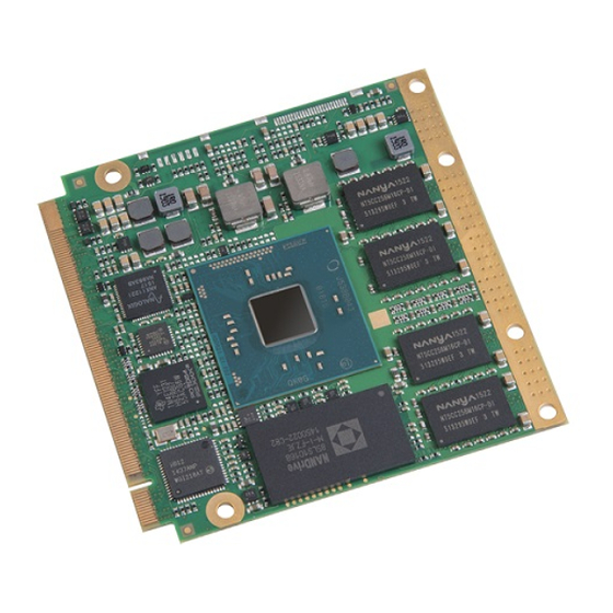
- Page 1 User Manual Qseven® Compact Module MSC Q7-BT Qseven® 2.0 Pinout Intel® Atom™ Series SOC Rev. 1.12 06/12/2020...
- Page 2 PREFACE Copyright Notice Copyright © 2015 MSC Technologies GmbH. All rights reserved. Copying of this document, and providing to others and the use or communication of the contents thereof, is forbidden without express authority of MSC Technologies GmbH. Offenders are liable to the payment of damages. All rights are reserved in the event of the grant of a patent or the registration of a utility model or design.
- Page 3 Certification MSC Technologies GmbH is certified according to DIN EN ISO 9001:2000 standards. Life-Cycle-Management MSC products are developed and manufactured according to high quality standards. Our life-cycle-management assures long term availability through permanent product maintenance. Technically necessary changes and improvements are introduced if applicable.
-
Page 4: Table Of Contents
CONTENTS INTRODUCTION ........................................11 Key Features ............................................11 Block Diagram ............................................16 Power Supply ............................................17 Power Dissipation ..........................................18 Mechanical Dimensions ........................................20 THERMAL SPECIFICATIONS....................................21 Heatspreader Concept ......................................... 21 Thermal Definitions ..........................................22 Thermal Management .......................................... 24 Power Management ..........................................25 Use Conditions ............................................. - Page 5 FUNCTIONS ON MODULE ....................................45 RTC ..............................................45 Solid State Drive (SSD) ........................................45 eMMC ..............................................46 SYSTEM RESOURCES......................................47 PCI Interrupt Routing ..........................................47 IRQ Lines ............................................. 48 6.2.1 Legacy IRQ Mode ............................................... 48 6.2.2 APIC Mode ................................................. 49 BIOS .............................................
- Page 6 7.8.21 I210 Gigabit Connection Settings ........................................77 Chipset ..............................................78 7.9.1 Flat Panel Configuration ............................................78 7.9.2 Backlight Control..............................................79 7.9.3 North Bridge ............................................... 80 ® 7.9.4 Intel IGD Configuration ............................................80 7.9.5 South Bridge............................................... 82 7.9.6 Azalia HD Audio ..............................................83 7.9.7 USB Configuration ..............................................
- Page 7 Table 1-1 Module Power Inputs ........................................ 17 Table 1-2 Power Dissipation ........................................19 Table 2-1 Temperature Range ........................................23 Table 3-1 Module Connector Pinout ......................................26 Table 4-1 HDA Signal Description ......................................29 Table 4-2 Ethernet Signal Description ....................................... 30 Table 4-3 SATA Signal Description ......................................
- Page 8 Table 7-13 BIOS CPU Menu ........................................63 Table 7-14 BIOS PPM Configuration......................................64 Table 7-15 BIOS IDE Configuration ......................................64 Table 7-16 BIOS Internal Devices Configuration ..................................65 Table 7-17 BIOS AMI Graphic Output Policy ....................................66 Table 7-18 BIOS CSM Configuration ......................................67 Table 7-19 BIOS NVMe ..........................................
- Page 9 Bios chapter Updated 21.03.2018 Bios chapter updated 26.03.2018 Bios chapter updated 10.10.2018 Bios Chapter updated 22.10.2018 Add WD Info 1.10 12.11.2019 Add comment, SSD, eMMC 1.11 14.05.2020 Changed to Avnet CI 1.12 12.06.2020 Minor corrections MSC Q7-BT MSC_Q7-BT_User_Manual.pdf 9 / 113...
- Page 10 REFERENCE DOCUMENTS ® Qseven Specification Revision 2.0 Last update: December 8th 2014 MSC Q7-BT MSC_Q7-BT_User_Manual.pdf 10 / 113...
-
Page 11: Introduction
1 Introduction ® Qseven modules are compact, highly integrated Single Board Due to the standardized mechanics and interfaces the system can be Computers. scaled arbitrarily. Despite the modular concept the system design is very flat and compact. ® Typically a Qseven module consists of a CPU, chipset, memory, ®... - Page 12 Audio: The MSC Q7-BT module provides a HDA link for audio codec connection. PCI Express Interface: 3x PCIe x1 Gen. 2.0 ports Ethernet: ® Gigabit Ethernet (Intel i210) , Vendor ID 8086, Device ID 1533 USB: 4x USB Host ports (USB1.1 and USB2.0) ...
- Page 13 SPI: Depending on the signal BIOS_DISABLE either SIO SPI or PCU SPI provided by the SoC is switched to the Q7 connector. PCU SPI is used during BIOS boot up phase, when starting from external BIOS flash on the carrier board. ...
- Page 14 Realtime Clock: SoC integrated RTC is used. Watchdog: Module provides a watchdog System Monitoring: Voltage monitoring supported for selected voltages on module. Temperature measurement at specifc points on the module. Fan speed monitoring for off module fan connector Power Management: ...
- Page 15 BIOS SuperIO support: Winbond 82627 HF SMSC SCH3112-NU SMSC SCH3114-NU EAPI support: The MSC Q7-BT supports the Embedded Application Programming Interface. EAPI drivers for various operating systems are available on the MSC technologies support website. (for details see chapter 10) For more information please contact MSC Technical Support +49 - 8165 906 –...
-
Page 16: Block Diagram
1.2 Block Diagram Figure 1-1 Block Diagram MSC Q7-BT MSC_Q7-BT_User_Manual.pdf 16 / 113... -
Page 17: Power Supply
1.3 Power Supply Table 1-1 Module Power Inputs Power Rail Description Primary power input Nominal Voltage Range +4.75V ... +5.25V Max. Input Ripple ±50mV Max. Voltage Rise rate < 250V/s VCC_5V_SB Standby power input Nominal All available VCC_5V_SB pins on the connector(s) shall Voltage Range +4.75V ... -
Page 18: Power Dissipation
1.4 Power Dissipation Benchmarks used: Passmark Burn-in Test : 100% CPU, 100% Memory, 100% Graphics 2D, 100% Graphics 3D Intel TAT stress tool for TDP (Thermal Design Power) and SDP (Scenario Design Power) The TDP is the maximal power dissipation for the package, this would in normal operation not be achieved, but the test can be used for profiling thermal solutions for cooling. - Page 19 Table 1-2 Power Dissipation Module S5 Soft off DOS prompt Win7-64b Win7-64b Burn-in test 100% state S3 suspend to idle 0.4W 3.4W 0.5W 2.7W 5.4W 8.7W 10.4W E3845 Quad Core 1.91GHz 0.4W 3.0W 0.5W 2.6W 4.0W 7.0W 7.7W E3826 Dual Core 1.46GHz 0.4W 3.2W...
-
Page 20: Mechanical Dimensions
1.5 Mechanical Dimensions Figure 1-2 Module Dimensions MSC Q7-BT MSC_Q7-BT_User_Manual.pdf 20 / 113... -
Page 21: Thermal Specifications
2 Thermal Specifications 2.1 Heatspreader Concept ® The cooling solution for a Qseven module is based on a heatspreader The heatspreader is not a heatsink! It is a defined thermal interface for concept. the system designer with fixed mechanical dimensions, so it should be possible to use different module types without problem. -
Page 22: Thermal Definitions
2.2 Thermal Definitions Tpcb This is the temperature of the outside surface of the module heat This is the temperature on the surface of the module PCB at point P spreader plate at point H (defined below). (defined below). Ths_max Tpcb_max This is the maximum temperature of the outside surface of the module The maximum temperature allowed for the surface of the module PCB... - Page 23 Figure 2-2 Measurement points for the thermal probe The stabilized temperature measured on the heat spreader and the module PCB during runtime mostly depends on the computing power demand from the application and the cooling solution implemented in the system. It is the responsibility of the system designer to provide a cooling solution in addition to the heat spreader that fulfils the requirements of the application.
-
Page 24: Thermal Management
2.3 Thermal Management The MSC Q7-BT modules have a number of mechanisms for regulating over temperature conditions, these are described below : 1. Critical shutdown If the Tcpu_junction temperature reaches 115°C (Atom E38xx), 110°C (Celeron J1900) or 105°C (Celeron N29xx) then the CPU will perform a system shutdown. -
Page 25: Power Management
2.4 Power Management The MSC Q7-BT modules have a number of mechanisms for regulating power. These are described shortly below and also in the BIOS section of this manual. In order make use of the power management features the operating system must be ACPI capable. The operating system th en adjusts the power consumption depending on the current load on the CPU and the power management settings configured in the BIOS and operating system. -
Page 26: Module Connector Pinout
3 Module Connector Pinout ® The pinout of the module connector is based on the Qseven specification [1]. Table 3-1 Module Connector Pinout Row A Row B Row A Row B SATA0_RX- SATA1_RX- GBE_MDI3- GBE_MDI2- GBE_MDI3+ GBE_MDI2+ BIOS_DISABLE# SDIO_CLK# GBE_LINK100# GBE_LINK1000# SDIO_CD# GBE_MDI1-... - Page 27 Row A Row B Row A Row B THRM# WDTRIG# eDP0_TX2- LVDS_B2- LVDS_A2- WDOUT (PU 10k 3.3V SUS) LVDS_PPEN LVDS_BLEN eDP0_TX3+ LVDS_B3+ LVDS_A3+ USB_SSTX0- USB_SSRX0- eDP0_TX3- LVDS_B3- USB_SSTX0+ USB_SSRX0+ LVDS_A3- USB_4_5_OC# USB_P5- USB_P4- eDP0_AUX+ LVDS_B_CLK+ USBDEV_SSTX1- USBDEV_SSRX1- LVDS_A_CLK+ USB_P5+ USB_P4+ eDP0_AUX- LVDS_B_CLK- USBDEV_SSTX1+...
- Page 28 Row A Row B Row A Row B DP_LANE2- LPC_AD2 LPC_AD3 TMDS_LANE0- LPC_CLK LPC_FRAME# SERIRQ DP_LANE0+ HDMI_CTRL_DAT (PU 10k 3.3V S0) TMDS_LANE2+ VCC_RTC SPKR DP_LANE0- HDMI_CTRL_CLK FAN_TACHOIN FAN_PWMOUT TMDS_LANE2- GP_TIMER_IN HDMI_HPD# DP_HPD# PCIE_CLK_REF+ PCIE_WAKE# SPI_MOSI SPI_CS0# PCIE_CLK_REF- PCIE_RST# SPI_MISO SPI_CS1# SPI_SCK VCC_5V_SB VCC_5V_SB...
-
Page 29: Module Connector Signal Description
4 Module Connector Signal Description An additional label, “SUS”, indicates that the pin is active during In the following tables signals are marked with the power rail associated with the pin, and for input and I/O pins, with the input suspend states (S3, S4, S5). -
Page 30: Ethernet
4.2 Ethernet Based on Intels i210 ethernet controller the module provides a 1Gb Ethernet MDI with twisted pair signals for an external transformer. The i210 includes a voltage mode line driver so it doesn’t require an analog powered center tap. Therefore Pin 15 GBE_CTREF specified in the ®... -
Page 31: Serial Ata
4.3 Serial ATA The Bay Trail-I SoC supports two SATA ports. If the SSD is populated on the module then this will use the second SATA interface (SATA1) otherwise both SATA ports are available. Table 4-3 SATA Signal Description Power Signal Pin Type Signal Level... -
Page 32: Pci Express
4.4 PCI Express The Bay Trail-I SoC supports four PCIe lanes. One PCIe lane is used for connecting the ethernet controller on the module. The remaining three PCIe x1 lanes are routed to the carrier board. On request a special BIOS version can be provided which combines PCIe lanes 0 and 1 into a x2 PCIe port. Table 4-4 PCIe Signal Description Power... -
Page 33: Usb
4.5 USB The USB controller on the module supports USB 3.0, USB 2.0 and USB 1.1. Depending on the BOM variant the different USB lanes on the Q7 connector are routed to different USB controllers or a USB hub on the module which designates the functionality for these USB lanes: ... - Page 34 Power Signal Pin Type Signal Level Available PU/PD Description Tolerance USB SS Suspend USBDEV_SSTX0- AC coupled USB 3.0 SuperSpeed transmit differential pair USBDEV_SSTX0+ on module USB 3.0 device USB SS Suspend USBDEV_SSRX0- USB 3.0 SuperSpeed receive differential pair USBDEV_SSRX0+ USB 3.0 device USB SS Suspend USB_SSTX0-...
-
Page 35: Lvds
4.6 LVDS The LVDS channel A signals are shared with the eDP signals. LVDS-Controller: Analogix ANX1122 Supported LVDS panels: Supported resolutions up to WQXGA (2560x1600, 60Hz, 24bpp) with pixel clock frequency up to 270MHz 18bpp and 24bpp Single and Dual Channels. - Page 36 Table 4-7 LVDS Signal Description Power Signal Pin Type Signal Level Available PU/PD Description Tolerance LVDS_A[0:3]+ LVDS Full On LVDS Channel A differential pairs LVDS_A[0:3]- LVDS_A_CK+ LVDS Full On LVDS Channel A differential clock LVDS_A_CK- LVDS_B[0:3]+ LVDS Full On LVDS Channel B differential pairs LVDS_B[0:3]- LVDS_B_CK+ LVDS...
-
Page 37: Edp
4.7 eDP The eDP signals shared with LVDS channel A. Table 4-8 eDP Signal Description Power Signal Pin Type Signal Level Available PU/PD Description Tolerance eDP0_LANE[0:3]+ Full On AC coupled Differential signal pair for DP lane [0:3] eDP0_LANE[0:3]- on module eDP0_AUX+ Full On AC coupled... -
Page 38: Spi Bus
Table 4-10 HDMI Signal Description Power Signal Pin Type Signal Level Available PU/PD Description Tolerance Full On TMDS differential signal pair [0:3] TMDS_LANE[0..3]+ AC coupled TMDS_LANE[0..3]- on module Full On TMDS differential clock TMDS_CLK+ AC coupled CLK+ PD 100k TMDS_CLK- on module CLK- PU 100k 3.3V HDMI_HPD#... -
Page 39: Off-Module Bios Implementation For Msc Q7-Bt
4.9.2 Off-module BIOS implementation for MSC Q7-BT ® Should the BIOS in the on-module SPI flash device be corrupted, the Qseven module can boot from an SPI flash device on the carrier board. This boot option may be used in case of emergency. It is not recommended to select the off-module BIOS flash as the preferred boot device in your application! ®... -
Page 40: Lpc Bus
4.10 LPC Bus Table 4-13 LPC Signal Description Power Signal Pin Type Signal Level Available PU/PD Description Tolerance LPC_AD[0:3] 3.3V CMOS Full On 3.3V PU 20k 3.3V LPC multiplexed address, command and data bus LPC_FRAME# 3.3V CMOS Full On 3.3V PU 20k 3.3V LPC frame indicates the start of an LPC cycle SERIRQ... -
Page 41: Uart
4.12 UART Table 4-15 UART Signal Description Power Signal Pin Type Signal Level Available PU/PD Description Tolerance UART0_TX O OD 3.3V CMOS Full On 3.3V PU 10k 3.3V UART transmit data UART0_RX 3.3V CMOS Full On 3.3V PU 10k 3.3V UART receive data 4.13 I²C Table 4-16... -
Page 42: Watchdog
4.14 Watchdog Table 4-17 Watchdog Signal Description Power Signal Pin Type Signal Level Available PU/PD Description Tolerance WDOUT O PP 3.3V CMOS Full On 3.3V PD 10k Output indicating that a watchdog time-out event has occurred. WDTRIG# 3.3V CMOS Full On 3.3V PU 1k 3.3V SUS Watchdog trigger input. -
Page 43: System Management
4.16 System Management Table 4-19 System Management Signal Description Power Signal Pin Type Signal Level Available PU/PD Description Tolerance PWRBTN# 3.3V CMOS Suspend 3.3V PU 10k 3.3V SUS Power button for powering system on or off. (Negative pulse) RSTBTN# 3.3V CMOS Suspend 3.3V PU 10k 3.3V SUS... -
Page 44: Sm Bus
4.17 SM Bus WARNING! It is strongly not recommended to use the SM Bus for communication with off-module devices! Table 4-20 SMB Signal Description Power Signal Pin Type Signal Level Available PU/PD Description Tolerance SMB_CLK I/O OD 3.3V CMOS Suspend 3.3V PU 10k 3.3V SUS System management clock line... -
Page 45: Functions On Module
5 Functions on Module 5.1 RTC BIOS SETUP data is stored in a non volatile Flash memory therefore all configuration data (except for time and date) will be retained during RTC- Power loss. 5.2 Solid State Drive (SSD) When using the on-module SSD SATA device, it should be taken into consideration that the lifetime of the device is affected by the number of read/write and erase cycles. -
Page 46: Emmc
5.3 eMMC When using the on-module eMMC storage device, it should be taken into consideration that the lifetime of the device is affected by the number of read/write and erase cycles. It is not recommended to use eMMC storage devices with applications which are continually storing large amounts of data. -
Page 47: System Resources
6 System Resources 6.1 PCI Interrupt Routing Table 6-1 PCI Interrupt Routing Table Slot Number IDSEL # or PIRQ 0 PIRQ 1 PIRQ 2 PIRQ 3 PIRQ 4 PIRQ 5 PIRQ 6 PIRQ 7 Bus # (or Onboard Device) DEV.# (INT A) (INT B) (INT C) -
Page 48: Irq Lines
6.2 IRQ Lines 6.2.1 Legacy IRQ Mode Table 6-2 IRQ Lines in Legacy IRQ Mode IRQ# Available Typical Interrupt Source Counter 0 Keyboard Cascade Interrupt from Slave PIC Limited In ACPI mode used for SCI Math coprocessor MSC Q7-BT MSC_Q7-BT_User_Manual.pdf 48 / 113... -
Page 49: Apic Mode
6.2.2 APIC Mode Table 6-3 IRQ Lines in Legacy APIC Mode IRQ# Available Typical Interrupt Source Connected to Pin Counter 0 Keyboard Cascade Interrupt from Slave PIC shared SCI Math processor PIRQA PIRQB PIRQC PIRQD MSC Q7-BT MSC_Q7-BT_User_Manual.pdf 49 / 113... - Page 50 IRQ# Available Typical Interrupt Source Connected to Pin MSC Q7-BT MSC_Q7-BT_User_Manual.pdf 50 / 113...
-
Page 51: Bios
7 BIOS 7.1 Introduction This guide describes the AMI Aptio Setup Startup screen and contains information on how to access Aptio setup to modify the s ettings which control AMI pre-OS (operating system) functions. 7.2 Startup Screen Overview The AMI Aptio Startup screen is a graphical user interface (GUI) that is included in AMI Aptio products. The default bios behavior is to show an informational text screen during bios POST phase, but the graphical boot screen can be enabled in the bios setup. -
Page 52: The Bios Menu Structure
7.6 The BIOS Menu Structure The BIOS Menu is structured in the following way: Table 7-1 BIOS Menu Structure Main Advanced Chipset Security Boot Save & Exit MSC Board Info Trusted Computing Flat Panel Configuration Admnistrator Password Boot Configuration Save Options Boot Device Priorities Boot Override Hardware Monitoring... -
Page 53: The Menu Bar
7.6.1 The Menu Bar The Menu Bar at the top of the window lists these selections: Table 7-2 BIOS Menu Bar Menu Items Description Main Use this menu for basic system information. Use this menu to set the Advanced Features available on your system’s chipset. Advanced Chipset Use this menu to set Chipset Features. -
Page 54: The Legend Bar
7.6.2 The Legend Bar Use the keys listed in the legend bar on the right side of the screen to make your selections, or to exit the current menu. The following table describes the legend keys and their alternates: Table 7-3 BIOS Legend Bar Function Exit submenu / Exit Setup utility without saving... -
Page 55: The Main Menu
7.7 The Main Menu You can make the following selections on the Main Menu itself. Use the sub menus for other selections. Table 7-4 BIOS Main Menu Feature Options Description Bios Vendor Informative Shows the Bios Vendor Core Version Informative Shows the Aptio Core Version Compliancy Informative... -
Page 56: Board Info
7.7.1 Board Info Table 7-5 BIOS MSC Board Info Feature Options Description Manufacturer MSC Technologies GmbH Board Name Informative Shows the board name Board Revision Informative Shows the board revision Bios Version Informative Shows the bios version Serial Number Informative Shows the boards serial number Boot Counter Informative... -
Page 57: Hardware Monitoring Measurement
7.7.2 Hardware Monitoring Measurement Note: The value shown in the BIOS and EAPI for the CPU temperature, is actually the temperature read by the Board controller from a sensor mounted on the board. At elevated temperatures the difference between the BIOS "CPU" temperature and the DTS temperature is 20°C (DTS is 20°C higher) Table 7-6 BIOS Hardware Monitoring Measurement Feature... -
Page 58: Firmware Update
7.7.3 Firmware Update Table 7-7 BIOS Hardware Monitoring Measurement Feature Options Description Configure Update Bios only, Entire Flash BIOS only: Update BIOS Region, Entire Flash: Update Entire Flash Preserve SMBIOS Variable Enabled, Disabled If Enabled, restore SMBIOS Variables (DMI Table) after Firmware Update. -
Page 59: The Advanced Menu
7.8 The Advanced Menu Table 7-8 BIOS Advanced Menu Feature Options Description Trusted Computing Submenu Trusted Computing ( TPM ) ACPI Settings Submenu System ACPI Parameters Serial Port Console Submenu Serial Port Console Redirection Redirection CPU Configuration Submenu CPU Configuration Parameters PPM Configuration Submenu CPU PPM Configuration settings... -
Page 60: Trusted Computing (Tpm 1.2)
7.8.1 Trusted Computing (TPM 1.2) Table 7-9 BIOS TPM Menu Feature Options Description TPM state Enabled Turn TPM Enable/Disable. NOTE: Your Computer will reboot during Disabled restart in order to change State of TPM. Pending Operation None Schedule an operation for the Security Device. Enable take ownership Note: Your computer will reboot during restart in order to change Disable take ownership... -
Page 61: Acpi Settings
7.8.3 ACPI Settings Table 7-11 BIOS ACPI Settings Feature Options Description Enable S4 Hibernation Enabled Enables or disables system ability to enter S4 state (Hibernate)). Disabled This option may not effective with some OS. Enable S3 Suspend Enabled Enables or Disabled System ability to enter S3 state (Suspend). Disabled This option may be not effective with some OS. -
Page 62: Console Redirection Submenu
7.8.5 Console Redirection Submenu Feature Options Description Terminal Type ANSI, VT100, VT100+, VT- Emulation: ANSI: Extended ASCII char set. VT100: ASCII char set. UTF8 VT100+: Extends VT100 to support color, function keys, etc. VT- UTF8: Uses UTF8 encoding to map Unicode chars onto 1 or more bytes. -
Page 63: Cpu Configuration
Feature Options Description Redirection after BIOS POST Always Enable, Bootloader The Settings specify if BootLoader is selected then Legacy console redirection is disabled before booting to Legacy OS. Default value is Always Enable which means Legaacy console Redirection is enabled for Legacy OS. 7.8.6 CPU Configuration Note: Dependent on used CPU, available setup options may vary!!! Table 7-13... -
Page 64: Ppm Configuration
Feature Options Description SW_ALL SW_ANY CPU C6 report Enabled Enable/Disable CPU C6(ACPI C3) report to OS Disabled Package C State limit Package C State limit No Limit 7.8.7 PPM Configuration Table 7-14 BIOS PPM Configuration Feature Options Description ® EIST Enabled Enable or disable Intel Speedstep... -
Page 65: Internal Devices Configuration
Feature Options Description Disabled SATA Speed Support Gen1 SATA Speed Support Gen1 or Gen2 Gen2 SATA Mode AHCI Mode Select IDE / AHCI IDE Mode SATA Port 0 Enabled Enable / Disable Serial ATA Port 0 Disabled SATA Port 0 HotPlug Enabled Enable / Disable Serial ATA Port 0 Hot Plug Disabled... -
Page 66: Ami Graphic Output Policy
Feature Options Description for drivers) 1.8V Support for SDcard Enabled Disable/Enable 1.8V Capability in SD Card controller Disabled Note: Windows 7 needs a Hotfix for SD usage (see MSC Website for drivers) DDR50 Support for SDCard Enabled Disable/Enable DDR50 Capability in SD Card controller Disabled PCU UART Enabled... -
Page 67: Csm Configuration
Feature Options Description IPv4 PXE Support Enabled, Disabled Enable Ipv4 PXE Boot Support. If disabled IPV4 PXE boot option will not be created IPv6 PXE Support Enabled, Disabled Enable Ipv6 PXE Boot Support. If disabled IPV6 PXE boot option will not be created PXE boot wait time 1-5s Wait time to press ESC key to abort the PXE boot... -
Page 68: Nvme
Feature Options Description Network Do not launch Controls the execution of UEFI and Legacy PXE OPROM UEFI only Note: for normal PXE boot from internal Lan controller set to Legacy only “legacy”. If an external Lan controller should have an UEFI Oprom, set to UEFI Storage Do not launch... -
Page 69: Sdio Configuration
7.8.14 SDIO Configuration Table 7-20 BIOS SDIO Configuration Feature Options Description SDIO Access Mode Auto, ADMA, SDMA Auto Option: Access SD device in DMA mode if controller supports it, otherwise in PIO mode. ADMA Option: Access Advanced DMA Transfer mode SDMA Option: Access Single Operation DMA Transfer mode DMA Option: Access SD device in DMA mode. -
Page 70: Usb Configuration
7.8.15 USB Configuration Table 7-21 BIOS USB Configuration Feature Options Description Legacy USB support Auto Enables Legacy USB support. Enabled AUTO option disables legacy support if no USB devices are Disabled connected. DISABLE option will keep USB devices available only for EFI applications. -
Page 71: Security Configuration
Feature Options Description USB Mass Storage Device Auto Select Mass storage device emulation type. (e.g USB Stick) Floppy Auto enumerates devices according to their media format. Optical Forced FDD drives are emulated as CDROM, drives with no media will be Hard Disk emulated according to a drive CD-ROM... -
Page 72: Sio Wb627/ Smsc 311X Configuration
7.8.17 SIO WB627/ SMSC 311x Configuration Table 7-23 BIOS SuperIO Configuration Feature Options Description COM A-D: Enabled Enable or disable COM A-D Disabled Note: Only SMSC SIO supports COM C and COM D COM A-D Setting: Auto Resource setting for COM A-D I/O 3F8h, IRQ 4 Note: Only SMSC SIO supports COM C and COM D I/O 3F8h, IRQ 3, 4, 5, 6, 7,... -
Page 73: Ec Hardware Monitoring
7.8.18 EC Hardware Monitoring Table 7-24 BIOS EC Hardware Monitoring Feature Options Description CPU Fan Control Manual, Define how the fan should be controlled: manually set to a fixed Sensor based duty cycle, or temperature based auto control. By CPU sensor Disabled, Fan is auto controlled by CPU if enabled. - Page 74 Feature Options Description Critical Temperature Limit 60-110°C Temperature threshold (in degrees celsius) at which the CPU [°C] should be throttled. Temperature is measured near the CPU and does not reflect ON DIE temperature. CPU Temperature Hysteresis 2°C The value (in degrees celsius) that the temperature has to fall below 4°C a certain threshold before the next lower fan speed will be selected.
-
Page 75: Legacy Irq Reservation
The temperature zones can be selected by temperature limits (T1, T2, T3). The following diagram explains the temperature based fan control: Marking Description PWM min Fan running with minimum speed (typically 25%) PWM mid Fan running with medium speed (typically 50%) PWM max Fan running with maximum speed (typically 100%) Temperature zone T<T1, Fan stopped... -
Page 76: Module-Specific Initialization
7.8.20 Module-specific Initialization Table 7-25 BIOS Module-specific Initialization Feature Options Description USB Port 1 Mode Auto Select the mode for USB port 1. Choose between host, device, or Host, auto-detection through USB_ID input signal. Device Lan Controller Enable or disable the onboard lan controller. Enabled Disabled User I2C Support... -
Page 77: I210 Gigabit Connection Settings
Feature Options Description 1min 5min Watchdog Action on Reset Reset System Select the action that should take place after a reset timeout occurs. Timeout Do Nothing Assert WDOUT POST Watchdog Enabled, Disabled Enable a watchdog during bios POST ( before OS boot). ATTENTION: if this watchdog is configured with timeouts that are too agressive, the board might not be able to boot anymore! Note: Values are valid not until before second boot. -
Page 78: Chipset
7.9 Chipset Table 7-26 BIOS Chipset Menu Feature Options Description Flat Panel Configuration Submenu Flat Panel Configuration North Bridge Submenu North Bridge Settings South Bridge Submenu South Bridge Settings 7.9.1 Flat Panel Configuration Table 7-27 BIOS Flat Panel Configuration Feature Options Description eDP Color Depth... -
Page 79: Backlight Control
Feature Options Description 1920x1080 panel will be set on this EDID data and Bios setup options for panel 1920x1200 type, mapping and channels will not be available anymore. LVDS Mapping 18bit Select LVDS mapping type 24bit LDI 24bit FPDI LVDS Spread Spectrum Disabled, +-0,25% to +- Configure the spread spectrum for the LVDS interface. -
Page 80: North Bridge
7.9.3 North Bridge Table 7-29 BIOS North Bridge Menu Feature Options Description ® Intel IGD Configuration Submenu IGD Configuration Max TOLUD Dynamic Top of low usable Memory Dynamic: Maximum value of TOLUD Dynamic assignment would 2.25 GB adjust TOLUD automatically based on largest MMIO length of 2.5GB installed graphic controller. - Page 81 Feature Options Description Secondary IGFX Boot Select secondary boot display Display Disabled IGD Turbo Mode Enabled Enable: IGD Turbo enabled Disabled Disable: IGD Turbo disabled Primary Display Select which of IGD/PCI Graphics device should be Primary Display Auto PCIe PAVC Disabled Enable/Disable Protected Audio Video Control Lite Mode...
-
Page 82: South Bridge
7.9.5 South Bridge Table 7-31 BIOS South Bridge Feature Options Description Azalia HD Audio Submenu Azalia HD Audio Configuration settings. USB Configuration Submenu USB Configuration settings PCI Express Configuration Submenu PCI Express Configuration settings Restore AC Power Loss Power Off Select AC power state when power is re-applied after a power Power On failure... -
Page 83: Azalia Hd Audio
7.9.6 Azalia HD Audio Table 7-32 BIOS HD Audio Menu Feature Options Description LPE Audio Support Disabled Select LPE Audio ACPI mode or PCI mode PCI mode ACPI mode Audio Controller Control Detection of the Azalia device. Enabled Disabled Disabled = Azalia will be unconditionally disabled Enabled = Azalia will be unconditionally Enabled Auto = Azalia will be enabled if present, disabled otherwise. -
Page 84: Usb Configuration
7.9.7 USB Configuration Table 7-33 BIOS USB Configuration Feature Options Description XHCI Mode Smart Auto Mode of operation of xHCI controller Auto Note: XHCI can only be enabled if EHCI is disabled!!! Enabled For Windows 7 it is recommended to install USB 3.0 driver in Disabled Auto mode, otherwise Mouse, Keyboard will not work for driver installation... -
Page 85: Pci Express Configuration
7.9.8 PCI Express Configuration Table 7-34 BIOS PCI Express Configuration Feature Options Description PCIE Dynamic Clock Gating Enabled Enable/Disable PCIE Dynamic Clock Gating. Disabled Enable or Disable the PCI Express Port 0 – Port 2 in the Chipset. PCI Express Port 0-2 Enabled Disabled Speed ( Port 0-2 ) -
Page 86: Security
7.10 Security Table 7-35 BIOS Security Menu Feature Options Description Administrator Password Set Password Set Setup Administrator Password User Password Set Password Set User Password HDDSecurity Configuration Set Password Set HDD Password Secure Boot menu Submenu Configure and enable Secure Boot Note: If ONLY the Administrator's password is set, then this only limits access to Setup and is only prompted for when entering Setup. -
Page 87: Key Management
Feature Options Description Key Management Submenu Enables expert users to modify Secure Boot Policy variables without full authentication 7.10.2 Key Management Feature Options Description Provision Factory Defaults Enabled, Disabled Allow to provision factory default Secure Boot keys when System is in Setup Mode “Enter”... -
Page 88: Boot
7.11 Boot Table 7-36 BIOS Boot Menu Feature Options Description Setup Prompt Timeout 1-65535sec Number of seconds to wait for setup activation key. 65535(0xFFFF) means wait forever. Bootup NumLock State Select the keyboard NumLock state Quiet Boot Enabled Enables/Disables Quiet Boot option Disabled Fast Boot Enabled... - Page 89 Feature Options Description Boot Priority 2 SATA Port 0/1, USB Port 0- Define which boot device should have the second highest boot 5, eMMC, SD Card, LAN, priority UEFI LAN, External Devices Boot Priority 3 SATA Port 0/1, USB Port 0- Define which boot device should have the third highest boot priority 5, eMMC, SD Card, LAN, UEFI LAN, External Devices...
-
Page 90: Save & Exit
Examples to restrict the boot device priority: #Example 1: Only the Harddisk on SATA Port 0 should be bootable: Select Boot Priority 1 to SATA Port 0 Set allow other devices to no #Example 2: USB Stick (legacy boot path) on Port 3 should have the highest boot priority. SATA HD the second. Select Boot Priority 1 to USB Port 3 Select Boot Priority 2 to SATA 0 Set Boot Option filter to Legacy only... - Page 91 Save Changes and Reset When you have completed the system configuration changes, select this option to save the changes and reboot the system, so the new system configuration parameters can take effect. Discard Changes and Reset Select this option to quit Aptio™ TSE without making any modifications to the system configuration Save Changes Selecting “Save Options”...
- Page 92 Launch EFI Shell from filesystem device Attempts to Launch EFI Shell application (Shellx64.efi) from one of the available filesystem devices. WARNING! This function will still work even if mass storage devices are not registered into the boot device list via MSC BIOS Configuration tool MBconf tool.
-
Page 93: Bios And Firmware Update
8 Bios and Firmware Update This update procedure is for newer BIOS versions, V1.50 or later. For older BIOS versions please see the relevant readme file or contact Technical Support. 8.1 Setup Controlled Update “MSC Firmware Update” integrated to define settings for BIOS updates and to start the update. Within BIOS Setup main menu there is a submenu Control flags define the section of FLASH which needs to be updated (BIOS only, complete FLASH, partial BIOS sections, etc.) and other options such as screen output, preserving DMI data, etc. -
Page 94: Bios Update From Efi Shell
8.2 Bios Update from EFI Shell BIOS Update - Batch Mode 1. Copy the contents of the .zip file onto an empty FAT32 formatted USB stick 2. Copy selected flash image file to \Recovery\FlashImg.bin 3. Make sure the USB stick is the first position of boot device list 4. -
Page 95: Blind Restoration Of Bios Default Settings (No Display Available)
8.5 Blind Restoration of Bios default settings (no display available) 1. Power up the System 2. Repeatedly press [DEL] for several seconds [F3] [F2] 3. Press for def5ault settings or for previous values. [Enter] 4. Press 5. Press [F4] [Enter] 6. -
Page 96: Bios Recovery (For Bios Version Older Than V1.50 )
8.7 Bios Recovery (for BIOS version older than V1.50 ) If a Bios update will be interrupted (e.g due to power loss) before the update has finished, it can happen that the system will not boot. In this case it is possible to restore the Bios with the following method: 9. -
Page 97: Clear Cmos And Recovery Jumper
8.8 Clear CMOS and Recovery Jumper There are two jumpers available on the module: Clear Backup EEPROM: By shorting the pins of this jumper during boot, the values of the Backup EEPROM and the values of the NV -ROM are invalidated, thus forcing the board to start up with default values. -
Page 98: Technotes
9 Technotes ® EIST (Enhanced Intel Speed Step) This allows the processor to meet the instantaneous performance needs of the operation being performed, while minimizing power draw and heat dissipation. Processor clock will be at its minimum possible frequency when in IDLE. When performing CPU loads, it will change its frequency up to its maximum frequency. - Page 99 TXT (Trusted Execution Technology) Due to the complexity of this feature, please visit: http://www.intel.com/content/dam/www/public/us/en/documents/white-papers/trusted-execution-technology-security-paper.pdf Note: To use this feature VT, Vt-d, SMX and TPM must be enabled. ® Intel VT and VT-d ® Increasing manageability, security, and flexibility in IT environments, virtualization technologies like hardware-assisted Intel ®...
- Page 100 Trusted Platform Module (TPM) A TPM is a cryptoprocessor that can store cryptographic keys that protect information. The Trusted Platform Module offers facilities for the secure generation of cryptographic keys, and limitation of their use, in addition to a hardware pseudo-random number generator. It also includes capabilities such as remote attestation and sealed storage.
- Page 101 PXE Boot Preboot eXecution Environment is used for booting from network controller. For legacy PXE boot ( legacy bootloader provided from PXE server ) the settings to enable PXE boot are to find in Configuration. If enabled, the lan controller will appear as boot device. For UEFI PXE boot ( UEFO bootloader provided from PXE Server), the Network stack must be enabled and the lan controller will appear as...
-
Page 102: Eapi
10 EAPI The "Embedded Application Programming Interface" (EAPI) used by this module provides a standardized interface for customer applications. This interface allows a user mode application access to hardware specific information as well as hardware resources. Following features are supported: ... -
Page 103: Bios Configurator Tool
11 BIOS Configurator Tool This tool is a Windows based tool and is available from MSC. It allows customers to configure the preferred default values in their BIOS, splash screen, custom LVDS display timing and other features. For more details please refer to the MSC Technologies Support Website or contact MSC Technical support. MSC Q7-BT MSC_Q7-BT_User_Manual.pdf 103 / 113... -
Page 104: Troubleshooting
12 Troubleshooting Issue 1: USB 3.0 stick causes hang at boot time Some USB 3.0 sticks/disks may cause BIOS hang at post code 0xB4, if XHCI mapping mode is not set to enabled. Solution: Please check for firmware update of the USB device. Alternatively the setting for XHCI mapping mode could be changed to enabled in the BIOS setup. - Page 105 Issue 5: Powercycle at startup If no RTC is used, System will perform a extra powercycle at startup because TXE is enabled as default. Disabling this opt ion in Bios setup will prevent the extra powercycle Issue 6: Linux / USB Gadget Driver: We discovered, that the USB Gadget driver may show problems in USB xHCI mode.
- Page 106 LICENSE ISSUES OPenSSL ====================== The OpenSSL toolkit stays under a dual license, i.e. both the conditions of the OpenSSL License and the original SSLeay license apply to the toolkit. See below for the actual license texts. Actually both licenses are BSD-style Open Source licenses.
- Page 107 software must display the following acknowledgment: "This product includes software developed by the OpenSSL Project for use in the OpenSSL Toolkit. (http://www.openssl.org/)" * 4. The names "OpenSSL Toolkit" and "OpenSSL Project" must not be used to endorse or promote products derived from this software without prior written permission.
- Page 108 * ARISING IN ANY WAY OUT OF THE USE OF THIS SOFTWARE, EVEN IF ADVISED * OF THE POSSIBILITY OF SUCH DAMAGE. * ==================================================================== * This product includes cryptographic software written by Eric Young * (eay@cryptsoft.com). This product includes software written by Tim * Hudson (tjh@cryptsoft.com).
- Page 109 * the code are not to be removed. * If this package is used in a product, Eric Young should be given attribution * as the author of the parts of the library used. * This can be in the form of a textual message at program startup or * in documentation (online or textual) provided with the package.
- Page 110 * FOR ANY DIRECT, INDIRECT, INCIDENTAL, SPECIAL, EXEMPLARY, OR CONSEQUENTIAL * DAMAGES (INCLUDING, BUT NOT LIMITED TO, PROCUREMENT OF SUBSTITUTE GOODS * OR SERVICES; LOSS OF USE, DATA, OR PROFITS; OR BUSINESS INTERRUPTION) * HOWEVER CAUSED AND ON ANY THEORY OF LIABILITY, WHETHER IN CONTRACT, STRICT * LIABILITY, OR TORT (INCLUDING NEGLIGENCE OR OTHERWISE) ARISING IN ANY WAY * OUT OF THE USE OF THIS SOFTWARE, EVEN IF ADVISED OF THE POSSIBILITY OF * SUCH DAMAGE.
- Page 111 modification, are permitted provided that the following conditions are met: 1. Redistributions of source code must retain the above copyright notice, this list of conditions and the following disclaimer. 2. Redistributions in binary form must reproduce the above copyright notice, this list of conditions and the following disclaimer in the documentation and/or other materials provided with the distribution.
- Page 112 Features -------- Internal crypto implementation (optional): - X.509 certificate processing in PEM and DER formats - PKCS #1 - ASN.1 - RSA - bignum - minimal size (ca. 50 kB binary, parts of which are already needed for WPA; TLSv1/X.509/ASN.1/RSA/bignum parts are about 25 kB on x86) Requirements ------------ wpa_supplicant was designed to be portable for different drivers and...
- Page 113 The original security mechanism of IEEE 802.11 standard was not designed to be strong and has proven to be insufficient for most networks that require some kind of security. Task group I (Security) of IEEE 802.11 working group (http://www.ieee802.org/11/) has worked to address the flaws of the base standard and has in practice completed its work in May 2004.
Need help?
Do you have a question about the Qseven MSC Q7-BT and is the answer not in the manual?
Questions and answers