
Subscribe to Our Youtube Channel
Related Manuals for Avnet MSC Technologies COM Express C6C-BW


Summary of Contents for Avnet MSC Technologies COM Express C6C-BW
- Page 1 User Manual COM Express Compact Module MSC C6C-BW Type 6 Pinout ® ® ® Intel Atom / Celeron / Pentium Series SOC Rev. 1.6 2018-07-11...
- Page 2 Preface Copyright Notice EMC Rules Copyright © 2017 MSC Technologies GmbH. All rights This unit has to be installed in a shielded housing. If not reserved. installed in a properly shielded enclosure, and used in accordance with the instruction manual, this product may Copying of this document, and providing to others and the cause radio interference in which case the user may be use or communication of the contents thereof, is forbidden...
- Page 3 Product Support MSC engineers and technicians are committed to provide support to our customers whenever needed. Before contacting Technical Support of MSC Technologies GmbH, please consult the respective pages on our web site at www.msc- technologies.eu/support/boards for the latest documentation, drivers and software downloads.
-
Page 4: Table Of Contents
Contents 2.12.16 Module Type Definition ..............38 USER INFORMATION ..............8 2.12.17 Power and GND ................39 About this Manual ................8 2.13 Pin List for MSC C6C-BW Module (Type 6) ........39 Symbols and Signal Words .............. 8 JUMPERS AND CONNECTORS..........45 Table Cells with Gray Text ............... - Page 5 6.8.15 SDIO Configuration ................71 6.14 Restore Bios settings from file ............99 6.8.16 USB Configuration ................71 6.15 Bios Recovery ................100 6.8.17 Security Configuration ..............72 6.16 Jumpers ..................101 6.8.18 SIO WB627/ SMSC 3114 Configuration ..........73 6.17 Post Codes ..................
- Page 6 Revision History Rev. Date Description 2017-03-22 First release 2017-03-27 Bios chapter updated 2017-03-30 Additional review results added 2017-06-19 Bios updated 2017-07-13 Bios updated 2018-01-04 Jumper description changed, TPM_PP function removed 2018-07-11 TPM corrected from SLB9635 to SLB9660 MSC C6C-BW MSC C6C-BW User Manual 6 / 107...
- Page 7 Reference Documents COM Express Module Base Specification COM Express Revision 2.1 Last update: April 10 , 2012 PCI Local Bus Specification Rev. 2.1 PCI21.PDF Last update: June 1 , 1995 http://www.pcisig.com ATA/ATAPI-6 Specification d1410r3b.pdf http://www.t13.org/ Serial ATA Specification Serial ATA 1.0 gold.pdf Last update: August 29 , 2002 Rev.1.0 http://www.sata-io.org/...
-
Page 8: User Information
1 User Information 1.1 About this Manual This user’s guide provides information about the components, features All safety messages have a safety alert symbol and are structured as and connectors available on the MSC C6C-BW COM Express follows: Compact Module. Danger, Warning or Caution 1.2 Symbols and Signal Words Type of hazard... -
Page 9: Intended Use
1.4 Intended Use 1.6 Electrostatic Sensitive Device High-performance embedded modules can perform various tasks in The MSC COM Express Compact Module is an infotainment systems, such as professional audio equipment for radio electrostatic sensitive device. It is packed accordingly. and television, or sophisticated illumination engineering for theater performances. -
Page 10: Technical Description
2 Technical Description 2.1 Introduction COM Express™ is an open specification from PICMG (PCI Industrial providing the interface infrastructure for the COM Express™ module Computer Manufacturer Group). It is a module concept to bring PCI using PC type connectors for external access. Express and other newer technologies like SATA, USB 3.0 and Currently four module sizes are defined in the COM Express different display interfaces onto a COM (Computer On Module). -
Page 11: Module Photos
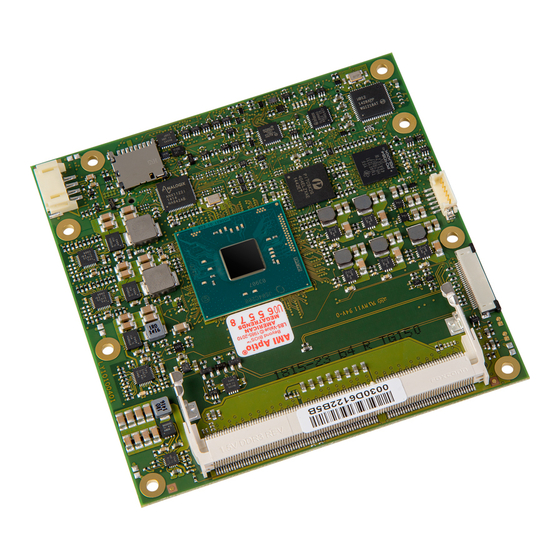
2.2 Module Photos Top side memory socket MAC address label Layout revision Board Identification label Fan connector µSD-Card socket BIOS label Top Side View MSC C6C-BW MSC C6C-BW User Manual 11 / 107... - Page 12 Bottom side memory socket COM Express® connector Board identification number (BID) Bottom Side View MSC C6C-BW MSC C6C-BW User Manual 12 / 107...
-
Page 13: Key Features
2.3 Key Features The MSC C6C-BW COM Express module is designed as a type 6 module according to COM Express® Module Base Specification Revision 2.1. Key features include: Module size: 95 mm x 95 mm BIOS support for Super IO Winbond 83627 HF and SMSC 3114 NU (on carrier board via LPC interface) ... -
Page 14: Block Diagram
2.4 Block Diagram MSC C6C-BW MSC C6C-BW User Manual 14 / 107... -
Page 15: Com Express Implementation
2.5 COM Express Implementation COM Express™ required and optional features for pin-out type 6 are summarized in the following table. The features identified as Minimum (Min.) shall be implemented by all modules. Features identified up to Maximum (Max) may be additionally implemented by a module. The column MSC C6C-BW shows the features implemented by the MSC module. - Page 16 A-B SMBus 1 / 1 A-B I 1 / 1 From GPIO: standard mode up to 100kb/s, from controller: Fast Mode up to 400kb/s A-B Watchdog Timer 0 / 1 A-B Speaker Out 1 / 1 A-B External BIOS ROM support 0 / 2 A-B Reset Functions 1 / 1...
-
Page 17: Functional Units
2.6 Functional Units ® CPUs Intel Atom X5-E8000, QC, 1.04GHz, 2.00 GHz 2MB L2 Cache, 5W, 2ch DDR3L ® ® (FCBGA 1170 Intel Celeron N3010, DC, 1.04GHz, 2.08GHz 2MB L2 Cache, 4W, 2ch DDR3L package) ® ® Intel Celeron N3060, DC, 1.60GHz, 2.16GHz 2MB L2 Cache, 6W, 2ch DDR3L ®... -
Page 18: Power Supply
TPM (option) Optional TPM module, TPM 1.2, SLB9660 Fan Supply 4-pin header for support of a 12V PWM fan ® Real Time Clock RTC integrated in Intel CMOS Battery External System Monitoring Voltages, temperatures, fan Core voltage 3.3V onboard voltage ... -
Page 19: Power Dissipation
2.8 Power Dissipation 2.8.1 Running Mode All measurements were made by plugging the MSC C6C-BW module onto a MSC MB-EVA6 carrier. The module was equipped with two 4GByte memory modules Hynix HMT451S6BFR8A-PB N0 AA, 4GB 1Rx8 PC3L-12800S-11-12-B4.1434 A, (8 chips each). The table below shows typical values which refer to consumption of the module itself without consumption of the base board and CPU fan. -
Page 20: Power Dissipation (Standby Modes)
2.8.2 Power Dissipation (Standby Modes) 1. System is shut down into “Soft Off” (S5) or “Suspend to Disk” 3. System is shut down into “Suspend to RAM” (S3) by Windows 7 (S4) by Windows 7 Professional 64-bit SP1. Professional 64-bit SP1. 2. -
Page 21: Mechanical Dimensions
2.10 Mechanical Dimensions 2.10.1 Compact Module There are two height options defined in the COM Express specification: 5mm and 8mm. The height option is defined by the connectors on the baseboard. MSC C6C-BW MSC C6C-BW User Manual 21 / 107... -
Page 22: Thermal Specifications
2.11 Thermal Specifications The cooling solution of a COM Express module is based on a heat- Humidity: 5 ... 95% (operating, non-condensing) spreader concept. 5 ... 95% (storage, non-condensing) A heat-spreader is a metal plate (typically aluminum) mounted on the top of the module. -
Page 23: Signal Description
2.12 Signal Description Pins are marked in the following tables with the power rail associated OD = Open Drain output. with the pin, and, for input and I/O pins, with the input voltage I/OD = Bi-directional Input/Open Drain Output Pin. tolerance. -
Page 24: Ethernet
2.12.2 Ethernet Signal Signal Power Remark / PU/PD/SR Description Source / Target Type Level Rail Tolerance GBE0_MDI[0:3]+ Analog 3.3V Sus 3.3V Gigabit Ethernet Controller 0: Media Dependent Interface Differential Intel® I210-AT GBE0_MDI[0:3]- Pairs 0,1,2,3. The MDI can operate in 1000, 100 and 10 Mbit / sec modes. -
Page 25: Pci Express Lanes
b. Number of vias used on the carrier board c. PCB material and specification used for the carrier board d. Target device 2.12.4 PCI Express Lanes Signal Signal Power Remark / PU/PD/SR Description Source / Target Type Level Rail Tolerance PCIE_TX[0:1]+ PCIe 1.0V... -
Page 26: Usb
2.12.6 USB Signal Signal Power Remark / PU/PD/SR Description Source / Target Type Level Rail Tolerance USB[0:4]+ 3.3V Sus 3.3V USB differential pairs, channels 0 through 4 BW SOC USB[0:4]- USB[5:7]+ 3.3V Sus 3.3V USB differential pairs, channels 5 through 7 USB HUB USB[5:7]- ePU = 10 KΩ... -
Page 27: Lpc Bus
2.12.7 LPC Bus Signal Signal Power Remark / PU/PD/SR Description Source / Target Type Level Rail Tolerance LPC_AD[0:3] CMOS 3.3V 3.3V LPC multiplexed address, command and data bus BW SOC LPC_FRAME# CMOS 3.3V LPC frame indicates the start of an LPC cycle BW SOC LPC_DRQ0# CMOS 3.3V... -
Page 28: Lvds / Edp
2.12.8 LVDS / eDP Signal Name LVDS option Pin Number Signal Name eDP option LVDS_A0+ eDP_TX2+ LVDS_A0- eDP_TX2- LVDS_A1+ eDP_TX1+ LVDS_A1- eDP_TX1- LVDS_A2+ eDP_TX0+ LVDS_A2- eDP_TX0- LVDS_A_CK+ eDP_TX3+ LVDS_A_CK- eDP_TX3- LVDS_VDD_EN eDP_VDD_EN LVDS_BKLT_EN eDP_BKLT_EN LVDS_BKLT_CTRL eDP_BKLT_CTRL LVDS_I2C_CK eDP_AUX+ LVDS_I2C_DAT eDP_AUX- RSVD eDP_HPD MSC C6C-BW... - Page 29 2.12.8.1 LVDS Flat Panel (mounting option, only available on modules with LVDS mounting option) Signal Signal Power Remark / PU/PD/SR Description Source / Target Type Level Rail Tolerance LVDS_A[0:3]+ LVDS LVDS Channel A differential pairs ANX1122 LVDS_A[0:3]- LVDS_A_CK+ LVDS LVDS Channel A differential clock ANX1122 LVDS_A_CK- LVDS_B[0:3]+...
-
Page 30: Digital Display Interfaces
Signal Signal Power Remark / PU/PD/SR Description Source / Target Type Level Rail Tolerance PCIe AC coupled eDP_AUX+ eDP_AUX+ BW SOC off module PCIe AC coupled eDP_AUX- eDP_AUX- BW SOC off module eDP_HPD CMOS 3.3V 3.3V Detection of Hot Plug / Unplug and notification of the link layer BW SOC 2.12.9 Digital Display Interfaces 2.12.9.1 Overview Type6 DDI Video Type Mapping... - Page 31 2.12.9.2 DisplayPort Signal Signal Power Remark / PU/PD/SR Description Source / Target Type Level Rail Tolerance DP1_LANE[0:3]+ AC coupled DisplayPort Lane [0:3] differential pairs. BW SOC DP1_LANE[0:3]- off module ePD = 100KΩ DP1_AUX+ AC coupled DisplayPort Aux control channel differential pair BW SOC on module ePU = 100KΩ...
- Page 32 Signal Signal Power Remark / PU/PD/SR Description Source / Target Type Level Rail Tolerance TMDS HDMI/DVI TMDS Clock differential pairs. BW SOC TMDS1_DATACLK+ AC coupled TMDS1_DATACLK- off module HDMI1_CTRLCLK CMOS 3.3V 3.3V ePD = HDMI/DVI Control Clock. Shared with DP1_AUX+. BW SOC 100KΩ...
-
Page 33: Serial Interface Signals
2.12.10 Serial Interface Signals Signal Signal Power Remark / PU/PD/SR Description Source / Type Level Rail Tolerance Target SER0_TX CMOS 3.3V 12V, 7mA General purpose serial port transmitter (output) BW SOC ePU = 47 KΩ SER0_RX CMOS 3.3V General purpose serial port receiver (input) BW SOC SER1_TX CMOS 3.3V... -
Page 34: Power And System Management
Signal Signal Power Remark / PU/PD/SR Description Source / Target Type Level Rail Tolerance ePD = 4.7 KΩ Trusted Platform Module (TPM) Physical Presence pin. Active high. TPM_PP CMOS 3.3V 3.3V Function not supported. NOTE: COM Express Specification R2.1 redefines the I2C bus to be in the suspend plane 3.3V_SUS rather than in the 3.3V plane. 2.12.12 Power and System Management Signal... - Page 35 Signal Signal Power Remark / PU/PD/SR Description Source / Target Type Level Rail Tolerance ePU = 10 KΩ BATLOW# CMOS 3.3V Sus 3.3V Indicates that external battery is low. BW SOC, Embedded NOTE: When pulled low, this line will prevent the system Controller from starting! ePU = 10 KΩ...
-
Page 36: General Purpose I/O
2.12.13 General Purpose I/O Signal Signal Power Remark / PU/PD/SR Description Source / Target Type Level Rail Tolerance BW SOC, Embedded GPI[0:3] CMOS 3.3V 3.3V General purpose input pins. Pulled high internally on the module. Controller These signals are multiplexed with SDIO interface. BW SOC, Embedded GPO[0:3] CMOS 3.3V... -
Page 37: Spi Interface
2.12.15 SPI Interface Signal Signal Power Rem. PU/PD/SR Description Source / Type Level Rail / Tol. Target ePU = 47 KΩ SPI_CS# CMOS 1.8V Sus 1.8V Chip select for Carrier Board SPI - may be sourced from chipset SPI0 or SPI1. BW SOC eSR = 22 Ω... -
Page 38: Module Type Definition
2.12.16 Module Type Definition Signal Signal Power Remark / PU/PD/SR Description Source / Target Type Level Rail Tolerance TYPE[0:2]# Type 6 module The TYPE pins indicate to the Carrier Board the Pin-out Type that is Carrier board logic implemented on the module. The pins are tied on the module to either ground (GND) or are no-connects (NC). -
Page 39: Power And Gnd
2.12.17 Power and GND Signal Signal Power Remark / PU/PD/SR Description Source / Target Type Level Rail Tolerance VCC_12V Power Wide input range for primary power input: +5.0V to17.0V Voltage Regulators Standby power input: +5.0V (±5%) VCC_5V_SBY Power 5V (±5%) VCC3.3V SUS If VCC5_SBY is used, all available VCC_5V_SBY pins on the regulator... - Page 40 GBE0_LINK# LPC_DRQ0# GBE0_MDI1- LPC_DRQ1# USB_SSRX2- USB_SSTX2- GBE0_MDI1+ LPC_CLK USB_SSRX2+ USB_SSTX2+ GND (FIXED) GND (FIXED) GND (FIXED) GND (FIXED) GBE0_MDI0- PWRBTN# USB_SSRX3- USB_SSTX3- GBE0_MDI0+ SMB_CK USB_SSRX3+ USB_SSTX3+ GBE0_CTREF SMB_DAT SUS_S3# SMB_ALERT# DDI1_PAIR6+ DDI1_CTRLCLK_AUX+ SATA0_TX+ SATA1_TX+ DDI1_PAIR6- DDI1_CTRLDATA_AUX- SATA0_TX- SATA1_TX- RSVD RSVD SUS_S4# SUS_STAT# RSVD...
- Page 41 AC/HDA_SYNC AC/HDA_SDIN1 DDI1_PAIR5+ DDI1_PAIR1+ AC/HDA_RST# AC/HDA_SDIN0 DDI1_PAIR5- DDI1_PAIR1- GND (FIXED) GND (FIXED) GND (FIXED) GND (FIXED) AC/HDA_BITCLK SPKR DDI2_CTRLCLK_AUX+ DDI1_PAIR2+ AC/HDA_SDOUT I2C_CK DDI2_CTRLDATA_AUX- DDI1_PAIR2- BIOS_DIS0# I2C_DAT DDI2_DDC_AUX_SEL DDI1_DDC_AUX_SEL THRMTRIP# THRM# RSVD RSVD USB6- USB7- DDI3_CTRLCLK_AUX+ DDI1_PAIR3+ USB6+ USB7+ DDI3_CTRLDATA_AUX- DDI1_PAIR3- USB_6_7_OC# USB_4_5_OC# DDI3_DDC_AUX_SEL...
- Page 42 LPC_SERIRQ CB_RESET# DDI3_PAIR3- DDI2_PAIR3- GND (FIXED) GND (FIXED) GND (FIXED) GND (FIXED) PCIE_TX5+ PCIE_RX5+ PEG_RX0+ PEG_TX0+ PCIE_TX5- PCIE_RX5- PEG_RX0- PEG_TX0- GPI0 GPO1 TYPE0# PEG_LANE_RV# PCIE_TX4+ PCIE_RX4+ PEG_RX1+ PEG_TX1+ PCIE_TX4- PCIE_RX4- PEG_RX1- PEG_TX1- GPO2 TYPE1# TYPE2# PCIE_TX3+ PCIE_RX3+ PEG_RX2+ PEG_TX2+ PCIE_TX3- PCIE_RX3- PEG_RX2- PEG_TX2-...
- Page 43 LVDS_A0+ LVDS_B0+ PEG_RX6+ PEG_TX6+ LVDS_A0- LVDS_B0- PEG_RX6- PEG_TX6- LVDS_A1+ LVDS_B1+ LVDS_A1- LVDS_B1- PEG_RX7+ PEG_TX7+ LVDS_A2+ LVDS_B2+ PEG_RX7- PEG_TX7- LVDS_A2- LVDS_B2- LVDS_VDD_EN LVDS_B3+ RSVD RSVD LVDS_A3+ LVDS_B3- PEG_RX8+ PEG_TX8+ LVDS_A3- LVDS_BKLT_EN PEG_RX8- PEG_TX8- GND (FIXED) GND (FIXED) GND (FIXED) GND (FIXED) LVDS_A_CK+ LVDS_B_CK+ PEG_RX9+...
- Page 44 SPI_MISO VGA_BLU PEG_RX12- PEG_TX12- GPO0 VGA_HSYNC SPI_CLK VGA_VSYNC PEG_RX13+ PEG_TX13+ SPI_MOSI VGA_I2C_CK PEG_RX13- PEG_TX13- TPM_PP VGA_I2C_DAT TYPE10# SPI_CS# RSVD RSVD SER0_TX RSVD PEG_RX14+ PEG_TX14+ SER0_RX RSVD PEG_RX14- PEG_TX14- A100 GND (FIXED) B100 GND (FIXED) C100 GND (FIXED) D100 GND (FIXED) A101 SER1_TX B101...
-
Page 45: Jumpers And Connectors
3 Jumpers and Connectors 3.1 Jumpers There are two jumpers available on the module: BIOS Default: By shorting the pins of this jumper during boot, the values of the BIOS setup will be reset to BIOS default values. Recovery BIOS Recovery: By shorting the pins of this jumper during boot the system is forced into crisis recovery BIOS mode. -
Page 46: Fan Connector
4 Watchdog 3.2 Fan Connector The connector of the fan is located at top side of the CPU module, directly beneath the CPU: The C6C-BW board has a watchdog function implemented by an The following connector type is used: embedded controller. ... -
Page 47: System Resources
5 System Resources 5.1 PCI IRQ Routing HW-option without PCIe switch (Chipset PCIe lane 2 is connected through PCIe switch to COMExpress connector lanes 2-4): Interrupts of Controller Slot Number Dev / PIRQ 0 PIRQ 1 PIRQ 2 PIRQ 3 PIRQ 4 PIRQ 5 PIRQ 6... -
Page 48: Smb Address Map
* OS with MSI support uses MSI interrupt (not shared with INTA-INTH) for this device. NOTE: Chipset PCIe lane 0 is connected to COMExpress connector lane 0. Chipset PCIe lane 1 is connected to COMExpress connector lane 1. Chipset PCIe lane 2 is connected to COMExpress connector lane 2. Chipset PCIe lane 3 is used for onboard LAN device. -
Page 49: Bios
6 BIOS 6.1 Introduction This guide describes the AMI Aptio Setup Startup screen and contains information on how to access Aptio setup to modify the s ettings which control AMI pre-OS (operating system) functions. 6.2 Startup Screen Overview The AMI Aptio Startup screen is a graphical user interface (GUI) that is included in AMI Aptio products. The default bios behavior is to show an informational text screen during bios POST phase, but the graphical boot screen can be enabled in the bios setup. -
Page 50: Bios Menu Structure
6.6 BIOS Menu Structure The BIOS Menu is structured in the following way: Main Advanced Chipset Security Boot Save & Exit MSC Board Info Trusted Computing Flat Panel Configuration Administrator Password Boot Configuration Save Options Boot Device Priorities Boot Override Hardware Monitoring ACPI Settings North Bridge... -
Page 51: Menu Bar
Main Advanced Chipset Security Boot Save & Exit USB Configuration Security Configuration WB627 SIO Configuration EC Hardware Monitoring Module-specific Initialization 6.6.1 Menu Bar The Menu Bar at the top of the window lists these selections: Menu Items Description Main Use this menu for basic system information. Use this menu to set the Advanced Features available on your system’s chipset. -
Page 52: Legend Bar
6.6.2 Legend Bar Use the keys listed in the legend bar on the right side of the screen to make your selections, or to exit the current menu. The following table describes the legend keys and their alternates: Function Exit submenu / Exit Setup utility without saving Left and right arrow keys Select Screen Up and down arrow keys... -
Page 53: Main Menu
6.7 Main Menu You can make the following selections on the Main Menu itself. Use the sub menus for other selections. Feature Options Description MSC Board Info Submenu Shows board specific information Submenu Shows the hardware sensors monitoring Hardware Monitoring Measurement Bios Vendor Informative... -
Page 54: Msc Board Info
6.7.1 MSC Board Info Feature Options Description Manufacturer MSC Technologies GmbH Board Name Informative Shows the board name Board Revision Informative Shows the board revision Bios Version Informative Shows the bios version Serial Number Informative Shows the boards serial number Boot Counter Informative Shows the amount of boots... -
Page 55: Hardware Monitoring Measurement
6.7.2 Hardware Monitoring Measurement Feature Options Description CPU Temperature Informative Shows CPU Temperature Also supported in EAPI NOTE: CPU temperature is measured close to the CPU and does not reflect CPU die temperature System Temperature Informative Shows CPU Temperature Memory Temperature Informative Shows CPU Temperature... -
Page 56: Advanced Menu
6.8 Advanced Menu Feature Options Description Trusted Computing Submenu Trusted Computing ( TPM ) ACPI Settings Submenu System ACPI Parameters Serial Port Console Submenu Serial Port Console Redirection Redirection CPU Configuration Submenu CPU Configuration Parameters PPM Configuration Submenu CPU PPM Configuration settings SATA Configuration Submenu AHCI SATA Configuration settings... -
Page 57: Trusted Computing (Tpm)
6.8.1 Trusted Computing (TPM) Feature Options Description TPM state Enabled Turn TPM Enable/Disable. NOTE: Your Computer will reboot Disabled during restart in order to change State of TPM. Pending Operation None Schedule an operation for the Security Device. Enable take ownership ... -
Page 58: Serial Port Console Redirection
6.8.3 Serial Port Console Redirection Feature Options Description Console Redirection Enable or Disable Com 0-2 Console Enabled Redirection Disabled Console Redirection settings Submenu The settings specify how the host computer and the remote Com 0-2 computer (which the user is using) will exchange data. Both computers should have the same or compatible settings. - Page 59 Feature Options Description Parity None, Even, Odd, Mark, A parity bit can be sent with the data bits to detect some Space transmission errors. Even: parity bit is 0 if the number of 1's in the data bits is even. Odd: parity bit is 0 if number of 1's in the data bits is odd.
-
Page 60: Cpu Configuration
6.8.5 CPU Configuration NOTE: Dependent on used CPU, available setup options may vary!!! Feature Options Description Limit CPUID Maximum Disabled for Windows XP Enabled Disabled Execute Disable Bit Enabled XD can prevent certain classes of malicious buffer overflow attacks Disabled when combined with a supporting OS ®... - Page 61 Feature Options Description Max CPU C-state This option controls Max C state that the processor will support MSC C6C-BW MSC C6C-BW User Manual 61 / 107...
-
Page 62: Ide Configuration
6.8.7 IDE Configuration Feature Options Description Serial-ATA (SATA) Enable / Disable SATA Enabled Disabled SATA Interface Type Gen1, Gen2, Gen3 Select SATA Interface Speed, CHV A1 always with Gen1 Speed. Aggressive LPM Support Enabled Enable PCH to aggressively enter link power state Disabled SATA Port 0 Enable / Disable Serial ATA Port 0... -
Page 63: Internal Devices Configuration
Feature Options Description Display Clock Spread Enabled Enable DISPLAY Clock Spread Spectrum feature. Spectrum Disabled Enable SATA Clock Spread Spectrum feature. SATA Clock Spread Enabled Spectrum Disabled 6.8.9 Internal Devices Configuration Feature Options Description SD Card Support ACPI Mode, PCI Mode, SCC SD Card Support Enable\Disable Disabled Use PCI Mode for Windows 7, ACPI Mode for Windows 10. -
Page 64: Ami Graphic Output Policy
NOTE: Only SER0 can be configured as PCU UART (with legacy resources IO=3F8h, IRQ=4) or as HS UART. 6.8.10 AMI Graphic Output Policy Feature Options Description Output Select Output Interface LVDS DDI1 BIST Enable Enabled Starts or stops the BIST on the integrated display panel (Built in self Disabled test) 6.8.11 PCI Subsystem Settings... - Page 65 Feature Options Description Disables Single Root IO Virtualization Support. Don’t reset VC-TC Mapping Enabled, Disabled If system has Vitrtual Channels, Software can reset Traffic Class mapping through Virtual Channels, to it's default state. Setting this option to Enabled will not modify VC Resources. PCI Express Settings Submenu Configure PCI Express...
- Page 66 Feature Options Description link if previous training attempt was unsuccessful. Link Training Timeout (uS) Time in uS Defines number of Microseconds software will wait before polling 'Link Training' bit in Link Status register. Value range from 10 to 10000 uS. Unpopulated Links Keep Link ON, Disabled In order to save power, software will disable unpopulated PCI...
- Page 67 Feature Options Description be initiated. IDO Completion Enable Enabled, Disabled If supported by hardware and set to 'Enabled', this permits setting the number of ID-Based Ordering (IDO) bit (Attribute[2]) requests to be initiated. LTR Mechanism Enable Enabled, Disabled If supported by hardware and set to 'Enabled', this enables the Latency Tolerance Reporting (LTR) Mechanism.
-
Page 68: Network Stack Configuration
Feature Options Description if OS does not support PCI Express and SHPC hot-plug natively. PCI Buses Padding Disabled, 4k, 8k, 16k, 32k Padd PCI Buses behind the bridge for Hot-Plug. I/O Resources Padding Disabled, 1M-128M Padd PCI I/O Resources behind the bridge for Hot-Plug Disabled, 1M-128M Padd PCI MMIO 32-bit Resources behind the bridge for Hot-Plug MMIO 32 bit Resources... - Page 69 Feature Options Description Disabled This module is able to emulate legacy BIOS environment and allow booting legacy operating systems or new operating systems which were installed without UEFI boot loader. If CSM is disabled, only EFI partitions can be booted. To disable CSM, first set Video Oprom to UEFI UPON Request –...
-
Page 70: Nvme Configuration
6.8.14 NVMe Configuration Feature Options Description Informative Device (connected NVMe NOTE: Only a connected NVMe device will appear here device) MSC C6C-BW MSC C6C-BW User Manual 70 / 107... -
Page 71: Sdio Configuration
6.8.15 SDIO Configuration Feature Options Description SDIO Access Mode Auto, ADMA, SDMA, PIO Auto Option: Access SD device in DMA mode if controller supports it,otherwise in PIO mode.DMA Option: Access SD device in DMA mode.PIO Option: Access SD device in PIO mode. SDIO Device Auto, Floppy, Forced FDD, Mass storage device emulation type. -
Page 72: Security Configuration
Feature Options Description USB transfer time-out 1 sec The time-out value for Control, Bulk, and Interrupt transfers. 5 sec 10 sec 20 sec Device reset time-out USB mass storage device Start Unit command time-out. 10 sec 20 sec 30 sec 40 sec Device power-up delay Auto... -
Page 73: Sio Wb627/ Smsc 3114 Configuration
Feature Options Description TXE EOP Message Enabled Send EOP message before enter OS Disabled TXE Unconfiguration Perform None Revert TXE settings to factory defaults 6.8.18 SIO WB627/ SMSC 3114 Configuration Feature Options Description COM A-D: Enabled Enable or disable COM A-D on Winbond SIO Disabled ... - Page 74 Feature Options Description LPT Mode: Mode setting for LPT on Winbond SIO EPP 1.9 ECP + EPP 1.9 Printer Mode EPP 1.7 ECP+EPP 1.7 PS/2 Controller Disabled Enable or disable the WB627 PS/2 controller. Enabled WB 627 / SMSC 3114 HW Disabled, Enabled Enable or disable the hardware monitoring interface.
-
Page 75: Ec Hardware Monitoring
6.8.19 EC Hardware Monitoring Feature Options Description CPU Fan Control Manual, Define how the fan should be controlled: manually set to a fixed Sensor based duty cycle, or temperature based auto control. By CPU sensor Disabled, If enabled, the cpu fan will be controlled by this temperature sensor Enabled By System sensor Disabled,... - Page 76 Feature Options Description Temperature Limit T1 [°C] 40°C Temperature threshold (in degrees celsius) at which the fan should 45°C be set to low speed duty cycle. 50°C For temperatures below this threshold, the fan will be off. NOTE: This option depends on selected temperature source (CPU/System/Board or a combination of these) Temperature Limit T2 [°C] 50°C...
- Page 77 Detail explanation how fan control is working: Detail explanation how fan control is working: Up to 2 Fans are supported, either by manual mode with fixed duty cycles or by temperature based mode with dynamic duty cycle s. The CPU fan is typically associated with the onboard CPU temperature sensor for automatic temperature control.
- Page 78 PWM min Fan running with minimum speed (typically 25%) PWM mid Fan running with medium speed (typically 50%) PWM max Fan running with maximum speed (typically 100%) Temperature zone T<T1, Fan stopped Temperature zone T1<T<T2, Fan running with minimum speed Temperature zone T2<T<T3, Fan running with medium speed MSC C6C-BW...
- Page 79 Temperature zone T2<T<T3, Fan running with maximum speed Minimum temperature limit starting Fan (selectable by SETUP) Temperature limit for medium Fan speed (selectable by SETUP) Temperature limit for maximum Fan speed (selectable by SETUP) Thyst Temperature hysteresis (selectable by SETUP) Temperature Control with multiple Sensors Fan control allows the association of any temperature sensor supported by embedded controller.
-
Page 80: Module-Specific Initialization
6.8.20 Module-specific Initialization Feature Options Description User I2C Support GPIO-based Select the type of user I2C support. Select GPIO-based for Controller-based Windows OS EAPI driver. Select controller-based for native I2C driver for Linux and Windows OS Shutdown Support ATX Mode, AT Mode ATX Mode means that the system will be turned off after shutdown. -
Page 81: Chipset
6.9 Chipset Feature Options Description Flat Panel Configuration Submenu Flat Panel Configuration North Bridge Submenu North Bridge Settings South Bridge Submenu South Bridge Settings 6.9.1 Flat Panel Configuration Feature Options Description eDP Color Depth 18bit, 24bit eDP colour depth selection. Adjust this according to the connected eDP display. -
Page 82: Backlight Control
Feature Options Description LVDS Mapping 18bit, 24bit LDI, 24bit FPDI Select LVDS mapping type 24bit LDI 24bit FPDI Number of LVDS channels Single Channel (1bpp) Select number of pixels transferred per clock Dual Channel (2bpp) LVDS Spread Spectrum Disabled, (+-) 0,25% - 1,75% Configure the spread spectrum for the LVDS interface. -
Page 83: North Bridge
6.9.3 North Bridge Feature Options Description ® Intel IGD Configuration Submenu IGD Configuration Memory Configuration Submenu Memory Configuration options Max TOLUD Dynamic Maximum Value of TOLUD. 2.25 GB 2.5GB 2.75GB MSC C6C-BW MSC C6C-BW User Manual 83 / 107... -
Page 84: Intel ® Igd Configuration
6.9.4 Intel ® IGD Configuration Feature Options Description Integrated Graphics Device Enabled Enable: Enable Integrated Graphics Device (IGD) when selected as Disabled the Primary Video Adaptor. Disable: Always disable IGD IGFX Boot Display VBIOS Default Select the Video Device which will be activated during POST. This has no effect if external graphics present. -
Page 85: Memory Configuration Options
Feature Options Description Spread spectrum clock Enabled Enable/Disable Spread Spectrum clock Disabled RC6 (Render Standby) Check to enable render standby support Enabled Disabled ISP Enable/Disable Enabled Enable/Disable ISP PCI Device Selection Disabled ISP PCI Device Selection Enabled Default ISP is PCI B0D2F0 for Window Boot. Linux Boot to Select Disabled B0D3F0 6.9.5 Memory Configuration Options... - Page 86 Feature Options Description Channel Selection Bit 3:0 0-9, A-F NOTE: Only bits [3:1] are used for final channel select value. BMISC Channel Select Bits 3:0: Specifies the address bits to use to stripe memory across multiple PMI channels. Channel Selection 4 0-9, A-F BMISC Channel select 4 for channel hashing.
-
Page 87: South Bridge
6.9.6 South Bridge Feature Options Description Security Configuration Submenu Security Configuration Azalia HD Audio Submenu Azalia HD Audio Configuration settings. USB Configuration Submenu USB Configuration settings PCI Express Configuration Submenu PCI Express Configuration settings Restore AC Power Loss Power Off Select AC power state when power is re-applied after a power Power On failure... -
Page 88: Azalia Hd Audio
Feature Options Description RTC Lock Enabled Enable or disable bytes 38h-3Fh in the upper and lower 128-byte Disabled bank of RTC RAM lockdown BIOS Lock Enable/Disable the BIOS Lock Enable feature Enabled Disabled Global SMI Lock Enabled Enable or Disable SMI lock. Disabled 6.9.8 Azalia HD Audio Feature... -
Page 89: Usb Configuration
6.9.9 USB Configuration Feature Options Description USB Port 0 Enable / Disable USB Port 0 Enabled Disabled USB Port 1 Enabled Enable / Disable USB Port 1 Disabled USB Port 2 Enabled Enable / Disable USB Port 2 Disabled USB Port 3 Enable / Disable USB Port 3 Enabled Disabled... -
Page 90: Pci Express Configuration
6.9.10 PCI Express Configuration Feature Options Description PCIE Express Root Port 1-4 Submenu Configure PCIE Express Root Port Settings Native PCIE Enable Enabled Disabled PCIe-Switch Power-Save Enabled Mode Disabled 6.9.11 PCIE Express Root Port 1-4 Feature Options Description PCI Express Root Port x Enabled Control the PCI Express Root Port. - Page 91 Feature Options Description SECE Enabled Root PCI Express System Error on Correctable Error Disabled Enable/Disable. PME SCI PCI Express PME SCI Enable/Disable. Enabled Disabled Ext Sync Enabled Enable Express Ext Sync Enable/Disable. Disabled PCIe Speed Auto, GEN1, GEN2 Configure PCIe Speed. CHV A1 always with Gen1 Speed. Detect Non-Compliance Enabled Detect Non-Compliance PCI Express Device.
-
Page 92: Security
6.10 Security Feature Options Description Administrator Password Set Password Set Setup Administrator Password User Password Set Password Set User Password HDDSecurity Configuration Set Password Set HDD Password NOTE: If ONLY the Administrator's password is set, then this only limits access to Setup and is only prompted for when entering Setup. If ONLY the User's password is set, then this is a power on password and must be entered to boot or enter Setup. - Page 93 Feature Options Description USB Support Disabled, Full Initial, Partial If Disabled, all USB devices will NOT be available until after OS Initial boot. If Partial Initial, USB Mass Storage and specific USB port/device will NOT be available before OS boot. If Full Initial, all USB devices will be available in OS and Post.
-
Page 94: Save & Exit
Feature Options Description Boot Option #1… Device x Sets the system boot order. Please note that UEFI boot entries will always have the highest priority. This list will be updated during next boot depending on the settings in the Advanced Boot Device ... - Page 95 Save Changes and Reset When you have completed the system configuration changes, select this option to save the changes and reboot the system, so th e new system configuration parameters can take effect. Discard Changes and Reset Select this option to quit Aptio™ TSE without making any modifications to the system configuration Save Changes Selecting “Save Options”...
- Page 96 Launch EFI Shell from filesystem device Attempts to Launch EFI Shell application (Shellx64.efi) from one of the available filesystem devices. WARNING! This function will still work even if mass storage devices are not registered into the boot device list via MSC BIOS Configuration tool MBconf tool.
- Page 97 Bios and Firmware Update If a System-BIOS update is required please follow these instructions: Bios Update from DOS: 1. Create a bootable DOS disk, USB Stick or hard disk and unpack the update tool AFUDOS.exe from AFUx64_303.msi 2. Copy the files “ ”, “...
-
Page 98: Blind Restoration Of Bios Default Settings (No Display Available)
Bios Update from EFI Shell Create a FAT32 formatted removable device and unpack the update tool AfuEfix64.efi from AFUx64_303.msi. 1. Copy an EFI Shell ( shellx64.efi ) into the root directory of the device. 2. Copy the files “ ”, “ ”, “... -
Page 99: Restore Bios Settings From File
6.14 Restore Bios settings from file It is possible to save configured Bios settings and copy these settings to other boards which have the same Bios version. 1. Configure the setup as required afudos.exe afuefix64.efi 2. Load DOS or EFI Shell with (for DOS) or (for EFI Shell). -
Page 100: Bios Recovery
6.15 Bios Recovery If a Bios update will be interrupted (e.g due to power loss) and the update has not been finished, it can happen that the system will not boot. In this case it is possible to restore the Bios with the following method: uefi.rom UEFI.rom 1. -
Page 101: Jumpers
6.16 Jumpers There are two jumpers available on the module: Clear Backup EEPROM: By shorting the pins of this jumper during boot, the values of the Backup EEPROM and the values of the NV-ROM are invalidated, thus forcing the board to start up with default values. BIOS Recovery: By shorting the pins of this jumper during boot the system is forced into crisis recovery mode. -
Page 102: Technotes
7 Technotes ® EIST (Enhanced Intel Speed Step) This allows the processor to meet the instantaneous performance needs of the operation being performed, while minimizing power draw and heat dissipation. Processor clock will be at its minimum possible frequency when in IDLE. When performing CPU loads, it will change its frequency up to its maximum frequency. - Page 103 TXT (Trusted Execution Technology) Due to the complexity of this feature, please visit: http://www.intel.com/content/dam/www/public/us/en/documents/white-papers/trusted-execution-technology-security-paper.pdf NOTE: To use this feature VT, Vt-d, SMX and TPM must be enabled. ® Intel VT and VT-d ® Increasing manageability, security, and flexibility in IT environments, virtualization technologies like hardware-assisted Intel ®...
-
Page 104: Eapi
Trusted Platform Module (TPM) A TPM is a cryptoprocessor that can store cryptographic keys that protect information. The Trusted Platform Module offers facilities for the secure generation of cryptographic keys, and limitation of their use, in addition to a hardware pseudo-random number generator. It also includes capabilities such as remote attestation and sealed storage. - Page 105 access to NVRAM access to I2C control GPIO’s control backlight set watchdog timer view sensor values of hardware monitor MSC provides a software package which is downloadable here after registration www.msc-technologies.eu/support/boards MSC C6C-BW MSC C6C-BW User Manual 105 / 107...
-
Page 106: Troubleshooting
9 Troubleshooting Issue 1: No USB available during Windows 7 Setup In spite of being available in BIOS setup, no USB is available during Windows 7 Setup from any standard install media. This is because the C6C-BW has no EHCI controller anymore, but just XHCI, and Windows 7 does not have native XHCI support out-of-the-box. - Page 107 Issue 4: SATA 6Gb/s SATA 6Gb/s behavior is functional only with SATA 6Gb/s cable. Solution: Use SATA 6Gb/s cable. Issue 5: Windows Installation If Windows Installation setup does not allow to install on harddisk try to make harddisk the first boot device in Bios setup. Issue 6: Windows 7 Installation USB 2.0 devices will not work during Windows 7 installation because Braswell has only USB 3.0 support and Windows 7 comes without USB 3.0 driver.
Need help?
Do you have a question about the MSC Technologies COM Express C6C-BW and is the answer not in the manual?
Questions and answers