
Related Manuals for Flashforge THOR500T


Summary of Contents for Flashforge THOR500T
- Page 1 Thor系列 ZN/EN-A01 User Guide The latest version of User Guide and slicing software can be Slicing Software found in the memory card, or contacting the equipment seller. 说明书/切片软件 最新版本说明书和切片软件可以在随机附带的存储卡中找到,或联系 设备销售商。...
- Page 2 300T Type Unpacking 1. Put the printer box at a clean and flat place. 2. Take out the tool box. 3. Check parts of the tool box: tool kit, memory 4. There is an unclogging pin tool, grease, Allen wrench, stamping wrench, PTFE tube card, screw bag, filament, ribbons, filament inside the tool kit.
- Page 3 7. Take out the filament shaft. 8. Remove foam blocks on both sides, and take out upper holder of the printer. 9. As is shown, hold the position that arrow 10. Remove the foam block on one side that has no extruder. points, and lift the printer base out of the carton.
- Page 4 400T / 500T Type Unpacking 1. Put the printer box at a clean and flat place. 2. Take out the tool box and filament. 3. Take out the upper holder of the printer and 4. Take out the filament shaft. put them at a clean place.
- Page 5 7. Take the build plate base out of the carton. 8. Put build plate on the table and check all the (Two-person operation is recommended) parts of the printer,no damage. 9. Check parts of the tool box: tool kit, memory 10.
- Page 6 Kit Contents Filament SD Card Filament Support 3D Printer Thor系列 ZN/EN-A01 User Guide The latest version of User Guide and slicing software can be Slicing Software found in the memory card, or contacting the equipment seller. 说明书/切片软件 最新版本说明书和切片软件可以在随机附带的存储卡中找到,或联系 设备销售商。 Quick Start Guide Power Cable Wrench Alen Wrench...
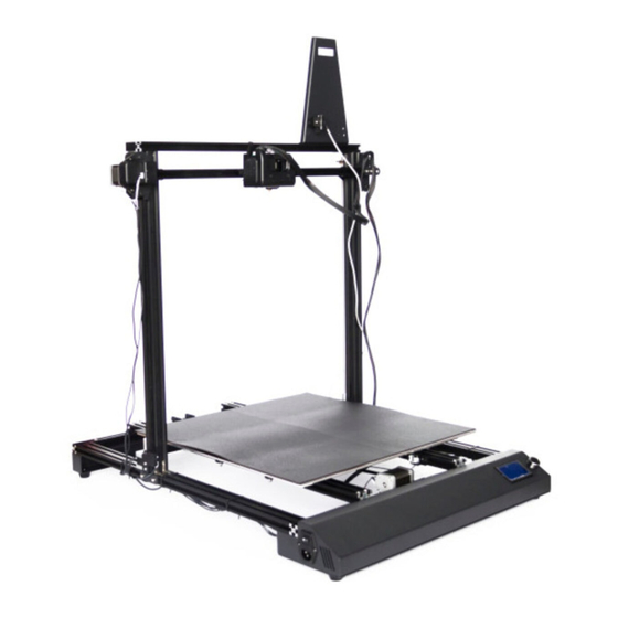
- Page 7 Getting to Know Your Thor 1. Filament detector 2. Filament support 3. Filament Fixed Seat 4. Extruder 5. Right Z-axis motor 6. Build plate 7. Right Z-axis motor cable 8. Y-axis motor and Y-axis sensor 9. Leveling sensor cable 10. Touch screen 11.
-
Page 8: Hardware Assembly
Hardware Assembly 1. As is shown, take out the upper holder on the 2. As is shown, take out two T-type fixed seats, table and remove protective foam. and put one of the T-type fixed seats with sensor on the left side. 3. - Page 9 7. As is shown, the upper holder should be fixed by L-type block and the printer. Adjust L-type block positions on both sides to align the screw hole that the arrow points. 8. Insert upper holder into L-type block on both 9.
- Page 10 12. Use 4 M4*8 screws to fix T-type fixed seats 13. Tighten screws on the T-type fixed seats. on both sides, two on each side. 14. As is shown, clip the square clip into the groove at the bottom of extruder base, thus making the back of extruder be close to extruder fixed seat.
- Page 11 17. Use 2 M4*8 screws to fix filament fixed seat 18. Clip extruder wiring hardness into clips on in the back. the filament fixed seats. 19. Find [Z-axis motor cable] on both sides marked with [Z-Steeper], insert them into Z-axis motor on both sides.
- Page 12 21. As is shown, find a shorter [Z-axis sensor 22. Insert Z-axis sensor cable into Z-axis sensor, cable] on the left of the printer. and sensor is inside the left T-type fixed seat. Attention: The side of the plug with two protuberances should be oriented to the right of the printer.
-
Page 13: Leveling Build Plate
Leveling Build Plate Base line 1. Tighten the four nuts of the build plate 2. Measure the height from the left side of the counterclockwise X-axis to the bottom section with a ruler. Base the height on the left, the height shall not be lower than 120mm. - Page 14 Let us know the function of leveling nuts before leveling How to use leveling nuts There are four leveling nuts under the build plate of Thor series printer, adjust the distance between build plate and nozzle by rotating leveling nuts. Rotate nut clockwise Rotate nut anticlockwise Raise the build plate to reduce the distance...
- Page 15 8. Put a A4 paper between nozzle and the build plate. Adjust the nut with one hand and feel the friction by sliding A4 paper back and forth with the other hand. [1]. If the paper slides through easily, the nozzle and the build plate are too far apart.Rotate the nut clockwise to increase the distance between them.
-
Page 16: Loading Filament
Loading Filament Print Preheat Tools 1. Press the spring presser, insert filament 2. Tap [Tools] vertically into the extruder bottom from filament intake. 3. Tap [Filament]. 4. Tap [Load] Attention: If the extruder cannot load filament for a long time,please check if 100% inserting filament into the extruder Extruder... - Page 17 First Print 1. Ensure that the build plate has been leveled before printing. 2. Ensure that the filament has been loaded in an appropriate approach. 3. Load the filament for a while to extrude all the melted filament you printed last time out of the extruder.
-
Page 18: Unloading Filament
For the change filament in the daily use, please operate follow Unloading Filament the steps below: 1. Plug filament guide tube out of the extruder 2. Tap [Tools] on the touch screen. filament intake, make sure that filament exposed 10cm for easily being pulled out. 3. - Page 19 Leveling Accessories Assembly Leveling accessories are not belong to the Standard accessories. Please contact device distributors to purchase if necessary. 1. Take out accessories. 2. As is shown, unfasten a nut and a spacer on the top of the sensor. 3.
- Page 20 7. Clip sensor cable into pulley clip on the top of filament fixed seat for sensor cable is too long. Sensor Height difference Nozzle 8. After installation completed, please compare the height between the nozzle and the bottom of the sensor. The sensor should be 1-2 mm higher than the nozzle. You can adjust the sensor height by adjusting nuts on the sensor.
- Page 21 300T机型开箱 1. 选择平整干净的地方放置打印机包装箱, 2. 取出工具盒。 打开纸箱。 3. 检查工具盒中的配件:工具袋、存储卡、螺 4. 工具袋中有通针、润滑油、内六角扳手 丝袋、耗材、扎带、丝盘固定座、丝盘轴、 开口扳手、聚四氟乙烯管。 Z轴T型固定座、Z轴T型固定座+传感器。 5. 螺丝袋中的螺丝从左至右分别是:M5*25 6. 取出中间所有的泡沫块以及泡沫下方的耗材。 螺丝4颗、M4*6螺丝5颗、M4*8螺丝4颗、 M4*5紧定螺丝8颗。...
- Page 22 7. 取出丝盘轴。 8. 移除左右两侧的泡沫块,取出下方的打印机 上支架。 9. 如图所示,抓住箭头所指的位置,将打印机 10. 移除未放置喷头一侧的泡沫块。 底座抬出纸箱。 11. 取出喷头,放在打印平台上,注意不要划伤 12. 移除剩下的泡沫块,开箱完成。建议妥善保 喷嘴。 存这些包装材料,以便于后续的存放或运输。...
- Page 23 400T / 500T机型开箱 1. 选择平整干净的地方放置打印机包装箱, 2. 取出工具盒、耗材。 打开纸箱。 3. 取出设备上架,摆放在干净的地方。 4. 取出丝盘轴。 5. 取出喷头,放在打印平台上,注意不要划伤 6. 取出泡沫。 喷嘴。...
- Page 24 7. 从纸箱中取出打印平台底座。(建议两人 8. 将打印平台底座平放置桌面,并检查打印机 操作) 各个部件完整,无损伤。 9. 检查工具盒中的配件:工具袋、存储卡、螺 10. 取出工具袋中有通针、润滑油、内六角扳手 丝袋、耗材、扎带、丝盘固定座、丝盘轴、 开口扳手、聚四氟乙烯管。 Z轴T型固定座、Z轴T型固定座+传感器。 型材机开箱完成。建议妥善保存这些包装 材料,以便于后续的存放或运输。 11. 螺丝袋中的螺丝从左至右分别是:M5*25 螺丝4颗、M4*6螺丝5颗、M4*8螺丝4颗、 M4*5紧定螺丝8颗。...
- Page 25 存储卡 丝盘轴 Thor系列 ZN/EN-A01 User Guide The latest version of User Guide and slicing software can be Slicing Software found in the memory card, or contacting the equipment seller. 说明书/切片软件 最新版本说明书和切片软件可以在随机附带的存储卡中找到,或联系 设备销售商。 扎 带 丝盘固定座 螺丝袋...
- Page 26 部件介绍 1. 丝料检测器 2. 耗材支架 3. 料盘架 4. 喷 头 5. 右侧Z轴电机 6. 打印平台 7. 右侧Z轴电机线 8. Y轴电机与Y轴传感器 9. 调平传感器线 10. 触摸屏 11. 电源线接口 12. 电源开关 13. 左侧Z轴传感器线 14. 左侧Z轴电机线 15. 左侧Z轴电机线与左侧X轴传感器线 19. X轴电机 16. 左侧Z轴传感器 17. 左侧Z轴电机 18. X轴传感器...
- Page 27 硬件安装 1. 如图所示,取出打印机上支架放于桌面, 2. 如图所示,取出两个T型固定座,带有传感器 去除保护泡棉。 的放在左边。 3. 将T型固定座上的螺丝略微旋松,使得固定座 4. 如图所示,调整T型螺母的方向,将带有传感 背后的T型螺母可以活动。 器的T型固定座插入上支架左侧。 5. 略微旋紧T型固定座上之前旋松的螺丝,请注 6. 用同样的方法将右侧的T型固定座装入右侧上 意,在这一步骤时请不要将这两颗螺丝拧紧。 支架。...
- Page 28 7. 上支架需要通过图中所示的 L 型内角件与打印机固定。如图所示,调整左右两侧 L 型内角件的 位置,使图中箭头所示的螺丝孔对齐。 8. 让左右两侧 L 型内角件插入上支架。 9. 用M5*25螺丝从底部拧紧,左右两侧各两颗, 共4颗。 10. 用M4*5紧定螺丝固定L型内角件,左右两侧 11. 如图所示,为固定两侧的T型固定座,在左 各4颗,共8颗。 右两侧滑槽内找到T型螺母(左右各两颗)。 将其调整到T型紧固件的两个螺丝孔位。...
- Page 29 12. 用M4*8的螺丝固定左右两侧的 T 型固定座, 13. 拧紧 T 型固定座上的螺丝。 左右两侧各两颗,共4颗。 14. 如图所示,将喷头固定座下方的方形卡扣卡入喷头底部凹槽,使喷头背部贴紧喷头固定座。 15. 用三颗M4*6的螺丝固定喷头。 16. 取出丝盘固定座,准备安装在上支架顶部。 请注意,安装料盘架时请确保装有丝料检测 开关的一侧朝向打印机正面。...
- Page 30 17. 用两颗M4*6螺丝从背后固定丝盘固定座。 18. 将喷头线束卡入丝盘固定座上滑轮前的卡扣。 19. 在打印机左右两侧找到标有[Z-Steeper]字样的[Z轴电机线]。将他们分别插入左右两侧的Z轴 电机。注意,在插入电机线时,插头上有两条突起的一面应当朝上。 20. 在打印机左侧找到标有[X-Steeper]字样的[X轴电机线]。将其插入X轴电机。 注意,X轴电机线的插口在电机下方。在插入电机线时,插头上有两条突起的一面应当朝向 打印机正面。...
- Page 31 21. 如图所示,在打印机左侧找到一根较短的 22. 将Z轴传感器线插入Z轴传感器,传感器位于 [Z轴传感器线]。 左侧T型固定座内侧。注意,插头上有两条 突起的一面应当朝向打印机右侧。 23. 如图所示,找到标有[X-Max]的[X轴传感器 24. 在打印机右侧找到一根较长的[丝料检测传 线]。将其插入X轴电机背后的X轴传感器插 感器线]。将其插入丝盘固定座上的丝料检 口。注意,插头上带有两条突起的一边朝向 测器。 打印机后方。 25. 注意在插入[丝料检测传感器线]时,插头上 26. 如图所示,用扎带固定[丝料检测传感器线]。 有两条突起的一边朝向打印机后方。 硬件安装完成。...
- Page 32 调 平 基准线 1. 将打印平台底部四颗螺帽逆时针拧紧。 2. 使用一把尺子测量x轴左侧至下部型材的高度; 以左侧为基准高度,其高度不得低于120mm; 3. 再测量X轴右侧至下部型材的高度,两侧高度 4. 手动旋转丝杆下方的联轴器,将其也调整为 必须保持一致。 X轴左右高度一致。 5. 电源线插入打印机左侧电源开关下方电源连 6. 将电源插头插入电源插座中,再打开电源开 接口。 关。...
- Page 33 在调平开始前,让我们先了解一下调平螺母的作用。 Thor系列打印机在打印平台下方共有4颗调平螺母,通过旋转调平螺母来调节 打印平台与喷嘴之间的距离。 顺时针旋转螺母,打印平台上升 逆时针旋转螺母,打印平台下降 打印平台上升,喷嘴与平台之间的间距变小 打印平台下降,喷嘴与平台之间的间距变大 Print Preheat Tools 7. 在触摸屏上点击[Tools],然后点击[Home],打印机开始回零,等待回零完成,点击[Yes]。 点击返回按键返回主界面。...
- Page 34 8. 取来一张A4纸,将其放入喷嘴与打印平台之间。一手调节调平螺母一手来回滑动A4纸来感受 摩擦力。 ① 若纸张可以轻松抽动则表示喷嘴与平台间距过大,需要顺时针旋转下方的调平螺母来缩小平 台与喷嘴的间距。 ② 若抽动纸张时阻力较大,表示喷嘴与平台的间距过小,需要逆时针旋转下方的调平螺母来增 大平台与喷嘴的间距。 ③ 若抽动纸张时感到有轻微的摩擦感,表明此时喷嘴与平台的间距比较合适,可以停止调节。 将喷头手动移动到第二个调平点上方。采用同样的方法对该点进行调节。以此类推,当四个 调平点都调平完成后(四个调平螺母上方),调平完成。 Thro系列打印机的喷头可以左右滑动,打印平台可以前后滑动。请通过手动滑动喷头和打印 平台将喷头调整到调平螺母的上方。...
- Page 35 填 装 耗 材 Print Preheat Tools 1. 按住压板将耗材从喷头进丝口垂直插入喷头 2. 点击[ Tools] 。 底部。 3. 点击[ Filament] 4. 选择[ load]。 注意:若长时间喷头未出丝,请检查 100% 填装耗材时是否正确将耗材插入喷头 Extruder 底部。 Cancel 5. 喷头预热到目标温度后,开始进丝,直至耗 材均匀出丝为止。点击返回按键,回到主界面。...
- Page 36 首 次 打 印 1. 打印开始前请确保打印机已经过调平; 2. 打印开始前请确保耗材安装正确,没有打结 或卡住; 3. 喷头内可能残留少量耗材,请进丝一段时间, 确保上一次打印的耗材已全部挤出; 4. 打印开始前请将喷头耗材清理干净; 5. 不可以在长时间无人看守的情况下使用 3D打印机; 1. 将存储卡插入设备卡槽内。 2. 在首界面点击[Build]。 3. 点击储存卡。 400_TEST 400_TEST.gcode 4. 选择需要打印的文件 5. 点击[Build]。 400_TEST Build Time 0:00 Extruder 178℃ Build plate 25℃ / 50℃ 6.
- Page 37 退丝操作 在日常使用中,如果需要更换耗材,请按下列步骤操作。 1. 将导丝管从喷头进丝口拔出,露出10厘米 2. 在触摸屏上点击[Tools]。 耗材,以便于拔出耗材。 3. 点击[ Filament ]。 4. 点击[Unload]。 Unload started, press down on the spring lever and withdraw filament Extruder Extruder Done 向下按压耗材3秒 5. 喷头开始加热。当喷头加热到预定温度后, 按下喷头侧边的压板,同时向下按压耗材 3秒,直到看到耗材从喷嘴处被挤出后快 速拔出丝料。 按下压板...
- Page 38 调平配件安装 调平配件不属于随机标配配件,如有需要请联系设备销售商购买。 1. 取出调平配件。 2. 如图所示,旋出感应器顶部的一个螺母和一个 垫片。 3. 将感应器穿过固定座。 4. 装回垫片后再装回螺母。 5. 将固定座放置于喷头右侧,用两颗螺丝固定。 6. 将感应器的插头于打印机液晶屏后部的传感 器线相连。...
- Page 39 7. 由于感应器线过长,请将感应器线卡入顶部丝盘固定座上的滑轮卡扣中。 感应器 高度差 约2mm左右 喷嘴 8. 安装完成后,请比对喷嘴与感应器下端的高低。感应器应当高于喷嘴1~2毫米。可以通过调节 感应器上的螺母来调节感应器的高低。...
Need help?
Do you have a question about the THOR500T and is the answer not in the manual?
Questions and answers