EarthWay Polar Tech 90399 Assembly Instructions Manual
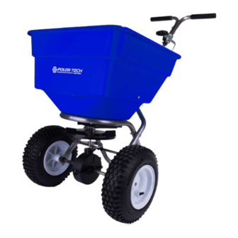
100lb stainless steel ice melt spreader
Hide thumbs
Also See for Polar Tech 90399:
- Assembly instructions manual (9 pages) ,
- Assembly instructions manual (9 pages)
Table of Contents
Advertisement
Quick Links
MODEL # 90399
Visit our EarthWay
website to see the
assembly video
Prior to assembly, you will need:
Needle nose pliers
#2 Phillips screwdriver
Two 7/16" adjustable or
box wrenches
2170_M52164_RevMar2021
100LB Stainless Steel
ASSEMBLY INSTRUCTIONS
THANK YOU
Thank you for selecting EarthWay for your
spreader needs. Our production team in
Northern Indiana takes pride in building this
spreader. Our customer support team is
standing ready to ensure your success.
Please contact us at www.EarthWay.com to
see our full line of commercial, lawn & garden tools.
NOTE: The large opening is designed to allow ice melt to flow
through spreader without the need for an agitator. This unit is
not designed for fertilizer
ASSEMBLY HARDWARE
¼" X 1"
Qty 2
¼" X 1 ½"
Qty 4
SPREADER COMPONENTS
HANDLES
AXLE
Ice Melt Spreader
.
¼" X 1 ½"
Qty 4
¼" X 2"
Qty 5
¼" X 2 1/4"
HOPPER
FRAME
FRAME
FOOT
X‐BRACE
PIVOT
IMPELLER
GEAR BOX
GUAGE
METER
ROD
PAGE 1
Advertisement
Table of Contents

Subscribe to Our Youtube Channel
Related Manuals for EarthWay Polar Tech 90399


Summary of Contents for EarthWay Polar Tech 90399
- Page 1 100LB Stainless Steel Ice Melt Spreader MODEL # 90399 ASSEMBLY INSTRUCTIONS THANK YOU Visit our EarthWay Thank you for selecting EarthWay for your website to see the spreader needs. Our production team in assembly video Northern Indiana takes pride in building this spreader. Our customer support team is standing ready to ensure your success. Please contact us at www.EarthWay.com to see our full line of commercial, lawn & garden tools. NOTE: The large opening is designed to allow ice melt to flow through spreader without the need for an agitator. This unit is not designed for fertilizer ASSEMBLY HARDWARE ¼” X 1” Qty 2 ¼” X 1 ½” Prior to assembly, you will need: Qty 4 ...
- Page 2 Assembly and Operation Instructions HELPFUL HINTS Read the directions before assembly. If your spreader does not spread evenly, be sure “FRONT” on the GEARBOX points to the front of the spreader. The impeller must turn clockwise when pushing forward. Reversing the GEARBOX during assembly will cause issues. Your spreader is calibrated for three miles per hour, which is a brisk walking speed. Slower or faster speeds will change the spread pattern. Do not use powdered materials as it will damage the gearbox. Gears are permanently lubricated at the factory. Do not open the GEARBOX or dirt may enter. SPREADER ASSEMBLY INSTRUCTIONS Remove all components and hardware Step 1: items from the box. Place the spreader hopper upside down and facing away from yourself. Install FRAME using (4) #14 x 1½″ Flat Step 2: Head Phillips screws. TIGHTEN THESE NOW Install impeller onto pinion shaft by Step 3: pressing the impeller as shown onto the pinion shaft and turning the impeller while holding the pinion shaft to engage with the COIN fully, and press down to secure. Next, insert Cross Brace thru the Gearbox Brace as shown above. 90399_M52162_Oct_2021.docx PAGE 2 ...
- Page 3 Assembly and Operation Instructions Install GEARBOX by inserting the PINION Step 4: SHAFT into hole in center of HOPPER bottom. The word “FRONT” on the GEARBOX must point to Front of the HOPPER. NOTE: Place PolarTech brand towards the front of the hopper. (A) Install Step 5: LOWER HANDLES onto FRAME to both sides as shown. Insert 2¼″ bolt through hole in LOWER HANDLE and through hole in FRAME install locknut. DO NOT TIGHTEN. (B) Now insert 1½″ bolt into the hole in LOWER HANDLE, then through FRAME brace. Next into threaded connector in CROSS BRACE. DO NOT TIGHTEN NOTE: Numbers on frame brace must be facing toward gear box as shown.
- Page 4 Places the bearings into the lower frame Step 6: using the “notch” on the bearing to fit into the “notch” on the LOWER AXLE FRAME. Next slide the axle through the bearings, through the GEAR BOX and into the other LOWER AXLE FRAME. Next, install AXLE BUSHING onto the axle, by placing the smaller end in first, slide over the AXLE, past the drilled holes. NOW GO BACK AND TIGHTEN ALL NUTS AND BOLTS STARTING WITH FIRST STEP. DO NOT OVER TIGHTEN. Install DRIVE WHEEL onto the AXLE and align Step 7: with the cotter pin hole nearest to LOWER HANDLE as shown. Insert 2″ cotter pin through wheel and through AXLE. Bend with pliers to prevent pin from falling out. Install COAST WHEEL onto the AXLE fully, then Step 8: using outside cotter pin hole, insert 1″ cotter pin through AXLE (not thru the wheel). Bend with pliers to prevent pin from falling out. New for 2021 EarthWay listened to customers who desired an adjustable handle for taller operators. Step 9: Select three ¼” x 2” bolts and three nylon lock nut to complete this step. Notice that the square handle shaft has two sets of holes in both ends. The end that the holes are closest to the end of the handle shaft is the top. Place it as shown inbetween the handles. Start by bolting through the handle spacer using the top most handle bar hole. Then bolt the gauge & lever assembly through the two center holes using two of your ¼” x 2” bolts. TIGHTEN ALL HARDWARE. 90399_M52162_Oct_2021.docx PAGE 4 ...
- Page 5 Assembly and Operation Instructions TALL OPERATOR CONFIGUATION – with the four handle holes, use the bottom two holes for the guage and use the top hole for the spacer. ...
- Page 6 Assembly and Operation Instructions Step 11: Step 10: (This step is only required if you want to change the position of the handles). NOTE: Thread hex nut onto the end of the pivot rod. BEFORE INSTALLING GAUGE AND UPPER Insert threaded end of the pivot rod into the shut off HANDLES TO HANDLE SHAFT, UPPER HANDLES plate. FEATURE THREE POSITONS FOR OPERATOR’S Thread an additional hex nut on the end of the pivot rod. COMFORT. If operator chooses middle or upper Use a 7/16” wrench to secure the hex nut in place around the positions, use handle spacer in hole nearest to shut off plate and pivot rod. handle grips. * See Image below. * Insert 2” bolt through upper handle, then C through handle spacer through other upper handle and secure with locknut. DO NOT A TIGHTEN LOCKNUT YET. TIGHTEN THIS NUT LAST. B ...
- Page 7 THE FLOW CONTROL LEVER MUST PLACE THE SHUT‐OFF PLATE IN THE FULL OPEN POSITION TO BE PROPERLY CALIBRATED. Now tighten the nuts against the PIVOT BRACKET to prevent change in calibration. OPERATING INSTRUCTIONS Before filling hopper, become familiar with the operation of this spreader. Move stop bolt on rate gauge assembly to the proper setting. While pushing spreader forward, pull control lever back to stop bolt. To stop, push lever forward to close flow holes before you stop moving. When finished, empty any remaining material from hopper. Thoroughly wash spreader and dry before storing. A coating of light oil will help prevent corrosion. CUSTOMER SERVICE SUPPORT@EARTHWAY.COM | www.EARTHWAY.com | 1009 Maple Street, Bristol, IN 46507 ONE YEAR WARRANTY EarthWay Products, Inc. warrants this product free of defects in original workmanship and materials for a period of one year to the end user with the original purchase receipt. If a manufacturing non‐conformance is found, EarthWay Products, Inc. at its discretion will repair or replace the part(s)/product at no charge provided the failure is not the result of incorrect installation, mishandling, misuse, tampering, or normal wear and tear as determined by EarthWay. EarthWay at its discretion may require that the part(s) or product be returned along with the original purchase receipt for examination and compliance with the terms of this warranty. Do not return any product without first receiving authorization from EarthWay Products, Inc. To seek remedy under this warranty, contact EarthWay Products, Inc. at support@earthway.com or write to EarthWay Products, Inc. 1009 Maple Street, Bristol, IN 46507 and describe the nature of the manufacturing defect. SPECIFIC LIMITATIONS: This warranty covers only the part(s) or product; any labor charges associated with repair or replacement of non‐conformances are specifically excluded. Due to the corrosive nature of most fertilizers and ice melt products, EarthWay Products, Inc. makes no warranty against and specifically excludes part(s) or product degradation or failure due to corrosion or its effects. ...
- Page 8 Assembly and Operation Instructions HOW TO ORDER SPARE PARTS – CALL or EMAIL: TURF DEPOT 800-305-9255 or earthway@turfdepot.com 100LB High Output Broadcast Spreader (90399) Parts List SERIES PART # DESCRIPTION SERIES PART # DESCRIPTION 40003 60333 SQUARE SCREEN GEABOX ASSEMBLY 99342 12110 HOPPER & SHUTOFF ASSEMBLY 9”...
Need help?
Do you have a question about the Polar Tech 90399 and is the answer not in the manual?
Questions and answers