Advertisement
Quick Links
Instructions
SD Composite, SD
and XD Series Hose
Reels
For dispensing air, water, antifreeze, windshield washer solvent, transmission fluid, oil and
grease. For professional use only.
Not for use in explosive atmospheres.
A complete list of Models, including Maximum Working Pressure, begins on page 2
Important Safety Instructions
Read all warnings and instructions in this
manual. Save these instructions.
SD Composite Series
(HR Models)
Patents
Community Design #001209712-001 (SD Series and XD Series only)
SD Series
(HP Models)
ti13159
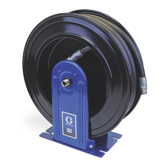
XD Series
(HS Models)
ti13192
XD Series
(HN Models)
313431H
ENG
ti13193
Advertisement

Related Manuals for Graco SD Composite Series


Summary of Contents for Graco SD Composite Series
- Page 1 Not for use in explosive atmospheres. A complete list of Models, including Maximum Working Pressure, begins on page 2 Important Safety Instructions Read all warnings and instructions in this manual. Save these instructions. SD Composite Series SD Series XD Series (HR Models) (HP Models)
- Page 2 Model No. indicates the hose reel color. For example: A = white, B = metallic blue, C = red, D = black, E = Mercedes blue, or F = yellow. (Other color choices may be available from your Graco Distributor.) On the table below this last character is represented by the generic # symbol.
- Page 3 Model No. indicates the hose reel color. For example: A = white, B = metallic blue, F = yellow. (Other color choices may be available from your Graco Distributor.) On the table below this last character is repre- sented by the generic # symbol.
- Page 4 Warnings Warnings The following warnings are for the setup, use, grounding, maintenance, and repair of this equipment. The exclama- tion point symbol alerts you to a general warning and the hazard symbol refers to procedure-specific risk. Refer back to these warnings. Additional, product-specific warnings may be found throughout the body of this manual where applicable.
- Page 5 Warnings WARNING MOVING PARTS HAZARD Moving parts can pinch or amputate fingers and other body parts. • Keep clear of moving parts. • Do not operate equipment with protective guards or covers removed. • Pressurized equipment can start without warning. Before checking, moving, or servicing equipment, follow the Pressure Relief Procedure in this manual.
- Page 6 Typical Installation Typical Installation A ground wire (G), bleed-type master air valve (E) and fluid drain valve (H) are required in your system installa- tion. These components help reduce the risk of serious injury, including electric shock and splashing in your eyes or on the skin.
- Page 7 . 1, using adapters if necessary. systems. However, it is not an actual system design. Contact your Graco distributor for assistance in design- • Fluid Drain Valve (H): install the drain valve point- ing a system to suit your needs.
- Page 8 Series Hose Reel in the same location that a Series 500 the lubricants and stress caused by hard pulls on the Hose Reel was previously installed. Order Graco Kit No. service hoses. See Technical Data, page 36 for 24A224. See F .
- Page 9 Installation NOTE: Always use all 4 large flat washers with 4 bolts to b. Remove 8 nuts (b) and 2 bolts (c) to rotate mount the hose reel pedestal to any surface. arm to desired position, AA, BB, CC, DD, or All Models c.
- Page 10 Installation Overhead Installations 4. Bolt hose reel to its mounting. Be sure it is secure before lowering the lift truck. To reduce the risk of injury, when you are mounting a hose reel overhead, always use a lift truck. HS Models Only 1.
- Page 11 Installation c. Pump solvent through line until fluid runs clear and is debris free. d. Pump lubricant through line until all solvent is flushed out. 7. For enclosed channel installations, continue with instructions on page 19. For all other installations, continue Step 8.
- Page 12 Installation Other Mounting Options Ceiling Mounting Without an I-Beam - Open Channel (All Models) (For HR or HP Model Reels Order Mounting Kit: 24A934, 24A935, 24A936, 24A937, 24A938 or 24A939. For HS or HN Model Reels Order Mounting Kit: 24A219, 24A220, 24A221, 24A222.) HR or HP Models: Open Channel Mounting Kits HS Models: Mounting Kits 24A934...
- Page 13 Installation Ceiling Mounting Directly to an I-Beam - HR Ceiling Mounting to I-Beam without Drilling and HP Models Only Holes - All models 1. Using the template (B), provided, drill holes in the (Order Mounting Bracket Kit: 204741 for open or I-Beam (C) (F .
- Page 14 Installation 5. Connect inlet supply line to inlet hose of the reel. c. Pump solvent through line until fluid runs clear See Hose Installation, page 16. and is debris free. d. Pump lubricant through line until all solvent is flushed out. 7.
- Page 15 Installation Wall Mounting (For HR or HP Model Reels Order Mounting Kit: 24A934, 24A935, 24A936, 24A937, 24A938 or 24A939. For HS or HN Model Reels Order Mounting Kit: 24A219, 24A220, 24A221, 24A222.) HR / HP Models: Open Channel Mounting Kits HS / HN Models: Mounting Kits 24A934 24A935...
- Page 16 Installation Hose Installation Installing a Hose on a Bare Reel 1. Locate length of your hose in table below. Note how many times you must turn the spring to properly pre- set spring tension. Hose Length No. of Reel Turns 35 ft (10.7 m) 50 ft.
- Page 17 Installation 10. Flush system. d. Pump lubricant through line until all solvent is flushed out. To avoid contaminating the fluid with line-scale, chips or other installation debris, before installing 11. Position hose stop so hose extends far enough for meter or dispense valve to end of hose, flush the all operators to reach dispensing valve.
- Page 18 Installation Dual Pedestal HS or HN Model Hose Reels 5. Firmly grasp the breaker bar with both hands and turn it clockwise one turn at a time to increase (tighten) spring tension. 6. Replace and partially tighten one screw. You can now remove the breaker bar.
- Page 19 24A951 - 20 NUT,spring SCREW, 10 - 24 x 5/8” PANEL, end LABEL, Graco logo 1. Bolt reel base to mounting channel. 2. Slide hose reel into the reel base (302). Install the hold-down plate (303), washer (305) and capscrew (304) as shown in F .
- Page 20 Installation NOTE: Although the hose reel can be installed on the reel base (302) with the guide arm positioned on the left or the right side, there is only one correct installation position. When the hose reel is correctly installed in the reel base, the reel will be centered over the reel base.
- Page 21 11. Clean and dry off surface of each end panel. Attach ing instructions provided with the dispense equip- a Graco label (404) to the center of each end panel. ment. 12. Position hose stop so hose extends far enough for all operators to reach dispensing valve.
- Page 22 Maintenance Maintenance Pressure Relief Procedure 1. Close the supply pump’s bleed-type master air valve (required for pneumatic systems). 2. Open the dispensing valve until pressure is fully relieved. ti13185 3. Open the fluid valve at the pump fluid outlet. Leave .
- Page 23 Maintenance spool. A new washer (5j) is installed on the new spool and is part of the new spool assembly. 8. Install new spool assembly (5). 9. Install guide arm and pedestal assembly (16 / 18) over spool (5) and install nut (5g). Tighten and torque nut to 85-105 ft.
- Page 24 Maintenance 8. Lay hose reel on its side so you can easily access Guide Arm and related parts are not included. the guide arm and pedestal (24 / 30). Remove long bolt (18) and washers (15 / 17) (F . 19 and F 20).
- Page 25 Maintenance Replacing the Service Hose 1. Relieve the pressure. 2. If the hose reel is enclosed, remove enclosures as necessary to access hose reel (F . 16). 3. Fully extend the hose (B) and latch the reel. 4. Attach a C-Clamp (A) to the reel flange to help pre- vent the reel from unintentionally becoming unlatched and spinning freely (F .
- Page 26 Maintenance 10. Attach the new hose (B) to the hose reel swivel (C) . 24) and carefully remove the C-Clamp (F 22). 11. Pull the hose hard (B) enough to release the latch and slowly allow the hose to retract. 12.
- Page 27 Parts SD Composite Series Parts SD Composite Series Part No. Description Part No. Description ◆ BUSHING, pawl KIT, spool (includes 5a-5h) (see page ◆ PAWL, ratchet ◆ SPRING, ratchet pawl ◆ WASHER, 26 mm (all HRL and HRM ◆ BOLT, M10 x 1.50 x 25...
- Page 28 Parts SD Series Parts SD Series Part No. Description Part No. Description 109158 HOSE, 50 ft (all HPH15 models) KIT, spool (includes 5a-5h) (see page 124461 HOSE, 50 ft (all HPH55 models) 253848 HOSE, 35 ft (all HPL23 models) ◆ WASHER, 26 mm (all HPL and HPM 253849 HOSE, 50 ft (all HPL25 models) models)
- Page 29 Parts SD Series ti13194 313431H...
- Page 30 Parts XD Series; HS Models Parts XD Series; HS Models Part No. Description Part No. Description 253849 HOSE, 50 ft (models HSL25A, KIT, spool (see page 33) (includes parts HSL25B) 5a-5j) ◆ 253850 HOSE, 65 ft (models HSL56A, RING, retaining ◆...
- Page 31 Parts XD Series; HS Models ti13196 313431H...
- Page 32 Parts XD Series; HN Models Parts XD Series; HN Models Part No. Description Part No. Description ◆ BASE, dual KIT, spool (see page 33) (includes parts ◆ SHAFT, swivel 5a-5j) ◆ PEDESAL ◆ RING, retaining ◆ SCREW, M8 X 1.25 x 20 ◆...
- Page 33 Kits Kits Spool Assembly Kits (page 33) Part No. Model. Size Media Line Size (inches) Length (feet) 15Y482 HRL56# Air/Water 15Y483 HRL65# Air/Water 15Y484 HRM65# 15Y485 HRH55# Grease HPL2D# 15Y486 Air/Water HPL25# HPL6D# 15Y487 Air/Water HPL65# 15Y488 HPL23# Air/Water 15Y489 HPL56# Air/Water 15Y490...
- Page 34 Kits Swivel Kits: 15Y480, 15Y481 Swivel Seal Kits: 24A952, 24953 (Instruction Manual: 313432) (Instruction Manual: 313432) Low and Medium Pressure Reels: 15Y480 24A952 Used with Low and Medium Pressure Reels Description SCREW M8 x 1.25 x 20 Description SCREW, M8 x 1.25 x 120 WASHER, 8 mm WASHER, 8 mm NUT, M8 x 1.25...
- Page 35 Kits Enclosure Retrofit Kit: 24C100 Hose Guide Kits (Instruction Manual: 313902) Roller Bracket Repair: 218591 Description (Instruction Manual: 406743) ARM, hose guide Description BASE, reel, enclosed BRACKET, hose guide NUT, lock PIN, roller SCREW ROLLER, hose WASHER, flat NUT, lock, #10 - 32 BOLT, m10 x 40lg SCREW, #10 - 32 x 3/4”...
- Page 36 Technical Data Technical Data Low Pressure Hose Reels and Hoses Fluid Pressure Air/Water, all hose diameters 300 psi (20.7 bar, 2.07 MPa) Inlet 1/2” NPSM Male Outlet 1/2”or 3/8” NPT Male Operating Temperature -20°F to 190°F (-28°C to 87°C) Wetted parts - Bare Hose Reel Only Zinc plated steel, anodized aluminum, Nitrile rubber Dimensions Page 37...
- Page 37 Technical Data Dimensions HR Models Pressure Size E† G◆ 3.5 inches 7.5 inches 4.7 inches 9 inches 21.8 inches 7.0 inches 19.2 inches Medium (89 mm) (191 mm) (120 mm) (229 mm) (554 mm) (177 mm) (487 mm) High † Measurement taken from base to top of bolts. ◆...
- Page 38 Technical Data HP Models Pressure Size E† G◆ 3.5 inches 7.5 inches 4.7 inches 9 inches 19.5 inches 7.0 inches 17.1 inches Medium (89 mm) (191 mm) (120 mm) (229 mm) (498 mm) (177 mm) (435 mm) High 3.5 inches 7.5 inches 4.7 inches 9 inches...
- Page 39 Technical Data HS Models Pressure Size E† G◆ 6.5 inches 7.5 inches 7.7 inches 9 inches 18.5 inches 7.5 inches 18 inches Medium (165 mm) (191 mm) (196 mm) (229 mm) (473 mm) (196 mm) (460 mm) High 6.5 inches 7.5 inches 7.7 inches 9 inches...
- Page 40 Technical Data HN Models Pressure Size 6.5 inches 7.5 inches 7.7 inches 9 inches 18.2 inches 20 inches Medium (165 mm) (191 mm) (196 mm) (229 mm) (463 mm) (508 mm) High 6.5 inches 7.5 inches 7.7 inches 9 inches 18.2 inches 20 inches Medium...
- Page 41 NOTES NOTES 313431H...
- Page 42 With the exception of any special, extended, or limited warranty published by Graco, Graco will, for a period as defined in the table below from the date of sale, repair or replace equipment covered by this warranty and determined by Graco to be defective.
Need help?
Do you have a question about the SD Composite Series and is the answer not in the manual?
Questions and answers