
Related Manuals for CYP nT17BX19


Summary of Contents for CYP nT17BX19
- Page 1 SOLUTIONS FOR GROWTH n - TECH SOLUTIONS nT17BX19/CPLUS-V4H2HA 4×2 HDMI Matrix with Audio Output Operation Manual Operation Manual...
- Page 3 DISCLAIMERS The information in this manual has been carefully checked and is believed to be accurate. Cypress Technology assumes no responsibility for any infringements of patents or other rights of third parties which may result from its use. Cypress Technology assumes no responsibility for any inaccuracies that may be contained in this document.
- Page 4 SAFETY PRECAUTIONS Please read all instructions before attempting to unpack, install or operate this equipment and before connecting the power supply. Please keep the following in mind as you unpack and install this equipment: • Always follow basic safety precautions to reduce the risk of fire, electrical shock and injury to persons.
-
Page 5: Table Of Contents
CONTENTS 1. Introduction ............1 2. Applications ............. 1 3. Package Contents ..........1 4. System Requirements ........2 5. Features ............2 6. Operation Controls and Functions ....3 6.1 Front Panel ..........3 6.2 Rear Panel ..........4 6.3 Remote Control (Optional) ......5 6.4 RS-232 Pinout and Defaults ...... -
Page 6: Introduction
1. INTRODUCTION This 4K UHD 4×2 HDMI Matrix with Audio Output provides the ability to connect up to four 4K UHD HDMI sources to up to two 4K UHD HDMI displays and freely switch between them. This unit comes with full support for 4K@60Hz (4:4:4, 8- bit) signals as well as support for 16-bit Deep Color, HDR (High Dynamic Range), 3D content, HD audio and other features defined by the HDMI 2.0 specification. -
Page 7: System Requirements
4. SYSTEM REQUIREMENTS • HDMI source equipment such as media players, video game consoles, or set-top boxes. • HDMI receiving equipment such as HDTVs, monitors, or audio amplifiers. • The use of Premium High Speed HDMI cables is highly recommended. 5. -
Page 8: Operation Controls And Functions
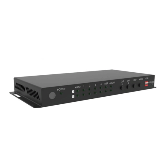
6. OPERATION CONTROLS AND FUNCTIONS 6.1 Front Panel POWER AUTO DISP. AUDIO DISP. AUDIO EDID SERVICE 1 2 3 4 IR Window: Accepts IR signals from the optional IR remote for control of this unit only. POWER LED: This LED will illuminate to indicate the unit is on and receiving power. -
Page 9: Rear Panel
EDID Dipswitch Block: Each dipswitch toggles the EDID source for the associated HDMI input between external EDID (DOWN), and internal EDID (UP). Note: The external EDID defaults to Output A’s EDID. The internal EDID supports 1080p60 with LPCM 2.0 audio for maximum compatibility. -
Page 10: Remote Control (Optional)
6.3 Remote Control (Optional) POWER Button: Press this button to power POWER the unit on or off. Note: The unit will also transmit the appropriate CEC/RS-232 on/off commands to any connected displays. OUT A 1~4 Buttons: Press any of these buttons to immediately switch Output A to the corresponding input. -
Page 11: Serial Commands
6.5 Serial Commands COMMAND Description and Parameters HELP Show the full command list. HELP N1 Show help details about the specified command. N1 = {Command name} GET MODEL NAME Show the unit’s model name. GET FW VER Show the unit’s current firmware version. SET SYSTEM REBOOT Reboot the unit. - Page 12 COMMAND Description and Parameters SET KEYLOCK N1 Enable or disable the front panel key lock. Available values for [Lock front panel] [Unlock front panel] GET KEYLOCK Show the current front panel lock state. SET FACTORY DEFAULT Reset the unit to the factory defaults. GET IN PORT NUMBER Show the total number of inputs on the unit.
- Page 13 COMMAND Description and Parameters GET IN N1 EDID DATA Show the EDID currently used by the specified input as ASCII hex data. Available values for [Input 1] [Input 2] [Input 3] [Input 4] GET IN N1 EDID INFORMATION Show English readable details derived from the EDID assigned to the specified input.
- Page 14 COMMAND Description and Parameters SET OUT N1 ROUTE N2 Route the specified input to the specified output. Available values for [Output A] [Output B] Available values for [Input 1] [Input 2] [Input 3] [Input 4] GET OUT N1 ROUTE Show the current input routed to the specified output. Available values for [Output A] [Output B]...
- Page 15 COMMAND Description and Parameters SET DISPLAY N1 N2 Send the CEC and designated RS-232 power on/o ffcommands to the specified display. Available values for [Display on output A] [Display on output B] Available values for [Transmit the “On” commands] [Transmit the “Off” commands] GET DISPLAY N1 Show the currently detected power status of the specified display.
- Page 16 COMMAND Description and Parameters GET DISPLAY N1 UART BAUD RATE Show the current baud rate of the specified RS-232 port. Available values for [Output A] [Output B] SET DISPLAY N1 UART DATA BIT N2 Set the data bits for the specified RS-232 port. Available values for [Output A] [Output B]...
- Page 17 COMMAND Description and Parameters SET DISPLAY N1 UART STOP BIT N2 Set the number of stop bits for the specified RS-232 port. Available values for [Output A] [Output B] Available values for [1 stop bit] [2 stop bits] GET DISPLAY N1 UART STOP BIT Show the current number of stop bits of the specified RS-232 port.
- Page 18 COMMAND Description and Parameters SET DISPLAY N1 POWER OFF COMMAND N2 Set the RS-232 “Power Off” command to use with the specified output’s display. Available values for [Output A] [Output B] N2 = {ASCII string} GET DISPLAY N1 POWER OFF COMMAND Show the current RS-232 “Power Off”...
Need help?
Do you have a question about the nT17BX19 and is the answer not in the manual?
Questions and answers