
Subscribe to Our Youtube Channel
Related Manuals for CYP CPLUS-V4H4HPA


Summary of Contents for CYP CPLUS-V4H4HPA
- Page 1 CPLUS-V4H4HPA 4K UHD 4 x 4 Matrix with Audio Output Operation Manual Operation Manual...
- Page 3 DISCLAIMERS The information in this manual has been carefully checked and is believed to be accurate. Cypress Technology assumes no responsibility for any infringements of patents or other rights of third parties which may result from its use. Cypress Technology assumes no responsibility for any inaccuracies that may be contained in this document.
- Page 4 SAFETY PRECAUTIONS Please read all instructions before attempting to unpack, install or operate this equipment and before connecting the power supply. Please keep the following in mind as you unpack and install this equipment: • Always follow basic safety precautions to reduce the risk of fire, electrical shock and injury to persons.
-
Page 5: Table Of Contents
CONTENTS 1. Introduction ............1 2. Applications .............1 3. Package Contents ..........1 4. SYSTEM REQUIREMENTS ........2 5. Features ............2 6. Operation Controls and Functions ....3 6.1 Front Panel ..........3 6.2 Rear Panel ..........5 6.3 Remote Control ......... 6 6.4 IR Cable Pinout .......... 7 6.5 RS-232 Pinout and Defaults ...... -
Page 6: Introduction
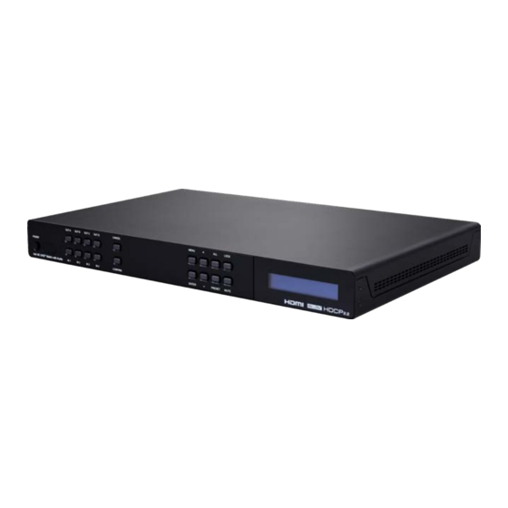
1. INTRODUCTION This 4K UHD 4×4 HDMI Matrix provides the ability to connect up to four 4K UHD HDMI sources to up to four 4K UHD HDMI displays and freely switch between them. This unit comes with full support for 18Gbps resolutions up to, and including 4K@60Hz (4:4:4, 8-bit) as well as support for 16-bit Deep Color, HDR (High Dynamic Range), HD audio and other features defined by the HDMI 2.0 specification. -
Page 7: System Requirements
4. SYSTEM REQUIREMENTS • HDMI source equipment such as media players, video game consoles or set-top boxes. • HDMI receiving equipment such as HDTVs, monitors or audio amplifiers. • The use of Premium High Speed HDMI cables is highly recommended. 5. -
Page 8: Operation Controls And Functions
6. OPERATION CONTROLS AND FUNCTIONS 6.1 Front Panel OUT A OUT B OUT C OUT D CANCEL MENU LOCK POWER UHD + 4x4 Matrix with Audio IN 1 IN 2 IN 3 IN 4 CONFIRM ENTER PRESET MUTE POWER Button: Press this button to power the unit on (green LED) or place it into stand-by mode (red LED). - Page 9 PRESET Button: Press to enter the preset recall menu in the LCD window. Press the “+/-” buttons followed by the “ENTER” button to select and activate the preferred preset. LOCK Button: Press to lock all button functions on the front panel. Press and hold for 3 seconds to release the lock function.
-
Page 10: Rear Panel
6.2 Rear Panel HDMI IN AUDIO / HDMI OUT SERVICE CONTROL RS232 IR IN DC 24V HDMI IN 1~4 Ports: Connect to HDMI source equipment such as media players, game consoles or set-top boxes. AUDIO/HDMI OUT A~D Ports: Connect the HDMI outputs to devices such as HDMI TVs, monitors or amplifiers for digital video and audio output. -
Page 11: Remote Control
6.3 Remote Control POWER Button: Press to power the unit on or place it into stand-by mode. 1 / A 5 / E INFO 2 / B 6 / F MUTE 1/A ~ 4/D Button: Press these keys to configure 3 / C 7 / G PRESET... -
Page 12: Ir Cable Pinout
6.4 IR Cable Pinout IR Extender Cable Infrared Power Ground 6.5 RS-232 Pinout and Defaults Serial Port Default Settings Baud Rate 19200 Data Bits DE-9 Female Port Parity Bits None Stop Bits Flow Control None... -
Page 13: Front Panel Lcd Menu
6.6 Front Panel LCD Menu All primary functions of this unit can be controlled by using the front panel LCD menu which is activated by pressing the MENU button on the front of the unit. Use the + (PLUS), − (MINUS), and ENTER buttons to navigate the LCD menu. - Page 14 EDID 2ND LEVEL 3RD LEVEL In 1~4 01 FHD 2Ch 02 FHD MCh 03 UHD 2Ch 04 UHD MCh 05 UHD+ 2Ch 06 UHD+ MCh 07 Sink A 08 Sink B 09 Sink C 10 Sink D 11 User 1 12 User 2 13 User 3 14 User 4...
- Page 15 In 1~4: Select the EDID to assign to each input independently. 6 internal EDIDs, 4 sink EDIDs and 4 user EDIDs are available. Press the “Enter” button to confirm the selection. After making a selection the change will occur immediately on that input. Note: After changing the EDID on an input, the video will typically black out briefly while the source adjusts to the new information.
- Page 16 Network Setup 2ND LEVEL 3RD LEVEL STATIC Mode DHCP [Current static IP address] Mask: [Current netmask] Gate: [Current gateway address] Mode: Set the unit to Static or DHCP mode. When DHCP mode is selected, all IP address information will be assigned automatically by the local DHCP server.
- Page 17 OSD Setup 2ND LEVEL 3RD LEVEL Out A Out B Out C Out D Out A~D: Enable or disable the OSD banner on each output. The change will occur after “Enter” has been pressed on a changed selection. CEC Send 2ND LEVEL 3RD LEVEL Out A~D...
- Page 18 Firmware 2ND LEVEL 3RD LEVEL Firmware [Current firmware version] 1) Firmware: Displays the unit’s current firmware version. Firmware Update 2ND LEVEL 3RD LEVEL Do USB Update? 1) Do USB Update: Selecting “Yes” will prepare the unit to update firmware via the USB port. After inserting a USB thumb drive containing a valid firmware file (*.bin format) the update process will begin.
-
Page 19: Webgui Control
6.7 WebGUI Control • Device Discovery Please obtain the “Device Discovery” software from your authorized dealer and save it in a directory where you can easily find it. Connect the unit and your PC/Laptop to the same active network and execute the “Device Discovery” software. Click on “Find Devices on Network”... - Page 20 • WebGUI Overview After connecting to the WebGUI’s address in a web browser, the login screen will appear. Please enter the appropriate user name and password then click “Submit” to log in. Note: The default user name and password is “admin”. On the left side of the browser you will see the following menu tabs where all primary functions of the unit are controllable via the built in WebGUI.
-
Page 21: Switch Tab
6.7.1 Switch Tab This page provides video routing settings, preset saving/loading, and I/O renaming options. To begin assigning a new video route, please click the button of the HDMI output you wish to send video to and then click on the button of the preferred HDMI input port. If desired, you may select more than one output prior to selecting the input. - Page 22 3) Edit Output: This window allows for changing a variety of settings related to the video output. ■ Output Name: To rename the output port, type the new name in the space provided in the Edit window. Click the “Save” button to confirm the change.
- Page 23 ■ OSD Background Color: Use the dropdown to select the preferred background color for the OSD custom text. Available colors are: black, white, red, green, blue, magenta, yellow, cyan, and gray. ■ OSD Background Color Transparent Level: Use the dropdown to select the preferred transparency level of the OSD custom text’s background.
-
Page 24: Edid Settings Tab
6.7.2 EDID Settings Tab This matrix provides the option of six standard EDIDs, four sink sourced EDIDs and four user uploaded EDIDs that can be assigned to each input port individually. The names of the four user uploaded EDIDs can changed if desired. - Page 25 Sink EDID Download: To save the EDID from one of the connected displays to your local PC, select the appropriate sink from the dropdown list then press the “Download” button. Depending on your browser settings you will either be asked where to save the downloaded file, or the file will be transferred to the default download location on your PC.
-
Page 26: System Settings Tab
6.7.3 System Settings Tab This page provides system configuration options including turning the unit’s power on/off, changing the network settings, resetting the system to factory defaults and updating the firmware. 1) Power: Press this switch to toggle the unit’s power between ON and OFF (standby mode). -
Page 27: Telnet Control
Note: The unit’s default IP address is 192.168.1.50. If the IP address is changed then the IP address required for WebGUI/Telnet access will also change accordingly. 5) Reset to Default: To reset the unit’s routing selections to the default settings, click the “Routing Reset” button. To reset the unit to its factory default state press the “Fadefault”... -
Page 28: Serial And Telnet Commands
6.9 Serial and Telnet Commands COMMAND Description and Parameters HELP Show the full command list. ? Show the full command list. P0 Turn the unit off (stand-by mode). P1 Turn the unit on. ST Show the unit’s current firmware version and routing status. FADEFAULT... - Page 29 COMMAND Description and Parameters SETIP N1 N2 N3 Set the IP address, netmask and gateway address to use when in Static IP mode. N1 = X.X.X.X [X = 0 ~ 255, IP address] N2 = X.X.X.X [X = 0 ~ 255, Netmask] N3 = X.X.X.X [X = 0 ~ 255, Gateway address] IPCONFIG...
- Page 30 COMMAND Description and Parameters STORE N1 Save all current routing assignments to the specified preset. N1 = 1~4 [Preset number] SHOW N1 List the routing assignments stored in the specified preset. N1 = 1~4 [Preset number] PRESET N1 Activate the routing assignments saved in the specified preset. N1 = 1~4 [Preset number] EM N1 N2...
- Page 31 COMMAND Description and Parameters BROADCAST N1 Enable or disable broadcast of command responses to control connections other than the current one. Available values for N1: [Enabled] [Disabled] BROADCAST Show the current status of the broadcast setting. CECOUT N1 N2 Send the specified command to the display connected to the specified HDMI output using CEC.
- Page 32 COMMAND Description and Parameters OSDSTR N1 N2 N3 Set the contents of the OSD banner text used on the specified output. N1 = 1~4 [Output port number] N2 = 1~2 [Text line number] N3 = {Text} [64 characters maximum] OSDFSIZE N1 N2 Set the font size for the OSD banner on the specified output.
- Page 33 COMMAND Description and Parameters [Green] [Blue] [Magenta] [Yellow] [Cyan] [Gray] OSDTS N1 N2 Set the transparency level for the background of the OSD banner on the specified output. N1 = 1~4 [Output port number] N2 = 1~8 [Transparency level] OSDINFO N1 Enable or disable replacing the custom OSD banner text with system information.
-
Page 34: Connection Diagram
7. CONNECTION DIAGRAM Blu-ray/Video Game Console Blu-ray/Video Game Console Blu-ray/Video Game Console IR Input Blu-ray/Video Game Console HDMI IN AUDIO / HDMI OUT SERVICE CONTROL IR IN RS232 DC 24V HDMI TV/Display Amplifier Active Speakers HDMI TV/Display HDMI TV/Display Power Supply Amplifier Active... -
Page 35: Specifications
8. SPECIFICATIONS 8.1 Technical Specifications HDMI Bandwidth 18Gbps Input Ports 4×HDMI (Type-A) Output Ports 4×HDMI (Type-A) 4×Analog Stereo (3.5mm) Control Ports 1×RS-232 (DE-9) 1×Ethernet (RJ-45) 1×IR Extender (3.5mm) Service Port 1×USB 2.0 (Type A) IR Frequency 38kHz Baud Rate 19200 Power Supply 24V/2.7A DC (US/EU standards, CE/FCC/UL certified) -
Page 36: Video Specifications
8.2 Video Specifications Input Output Supported Resolutions (Hz) HDMI HDMI 720×400p@70/85 640×480p@60/72/75/85 720×480i@60 720×480p@60 720×576i@50 720×576p@50 800×600p@56/60/72/75/85 848×480p@60 1024×768p@60/70/75/85 1152×864p@75 1280×720p@50/60 ... -
Page 37: Audio Specifications
Input Output Supported Resolutions (Hz) HDMI HDMI 2560×1600p@60RB 2048×1080p@24/25/30 2048×1080p@50/60 3840×2160p@24/25/30 3840×2160p@50/60 (4:2:0) 3840×2160p@24, HDR10 3840×2160p@50/60 (4:2:0), HDR10 3840×2160p@50/60 4096×2160p@24/25/30 4096×2160p@50/60 (4:2:0) ... -
Page 38: Analog Audio
8.3.2 Analog Audio Analog Output Max Audio Level 2Vrms THD+N < −60dB@0dBFS 1kHz (A-wt) > 70dB@0dBFS Frequency Response < ±3dB@20Hz~20kHz Crosstalk < −60dB@10kHz Impedance 470Ω Type Unbalanced 8.4 Cable Specifications 1080p 4K30 4K60 (4:4:4) (4:4:4) Cable Length 8-bit 12-bit 8-bit 8-bit High Speed HDMI Cable HDMI Input... -
Page 39: Acronyms
9. ACRONYMS ACRONYM COMPLETE TERM ASCII American Standard Code for Information Interchange Cat.5e Enhanced Category 5 cable Cat.6 Category 6 cable Cat.6A Augmented Category 6 cable Cat.7 Category 7 cable Consumer Electronics Control Command-Line Interface Digital-to-Analog Converter Decibel DHCP Dynamic Host Configuration Protocol Digital Visual Interface EDID Extended Display Identification Data... - Page 40 ACRONYM COMPLETE TERM Megahertz On-Screen Display Signal-to-Noise Ratio Transmission Control Protocol THD+N Total Harmonic Distortion plus Noise TMDS Transition-Minimized Differential Signaling Ultra-High-Definition (10.2Gbps) UHD+ Ultra-High-Definition Plus (18Gbps) UHDTV Ultra-High-Definition Television Universal Serial Bus Video Graphics Array WUXGA (RB) Widescreen Ultra Extended Graphics Array (Reduced Blanking) Extended Graphics Array Ω...
- Page 44 CYPRESS TECHNOLOGY CO., LTD Home page: http://www.cypress.com.tw...
Need help?
Do you have a question about the CPLUS-V4H4HPA and is the answer not in the manual?
Questions and answers