
Related Manuals for CYP CPLUS-V4H2HPIP


Summary of Contents for CYP CPLUS-V4H2HPIP
- Page 1 SOLUTIONS FOR GROWTH n - TECH SOLUTIONS CPLUS-V4H2HPIP | nT22AX16 4×2 HDMI Matrix with PiP Operation Manual Operation Manual...
- Page 3 DISCLAIMERS The information in this manual has been carefully checked and is believed to be accurate. Cypress Technology assumes no responsibility for any infringements of patents or other rights of third parties which may result from its use. Cypress Technology assumes no responsibility for any inaccuracies that may be contained in this document.
- Page 4 SAFETY PRECAUTIONS Please read all instructions before attempting to unpack, install or operate this equipment and before connecting the power supply. Please keep the following in mind as you unpack and install this equipment: • Always follow basic safety precautions to reduce the risk of fire, electrical shock and injury to persons.
-
Page 5: Table Of Contents
CONTENTS 1. Introduction ............1 2. Applications ............. 1 3. Package Contents ........... 1 4. System Requirements ........2 5. Features............2 6. Operation Controls and Functions ....3 6.1 Front Panel ..........3 6.2 Rear Panel........... 5 6.3 RS-232 Pinout and Defaults ......6 6.4 OSD Menu ........... -
Page 6: Introduction
1. INTRODUCTION This 4 by 2 HDMI Matrix with PiP is a high performance HDMI switch with integrated scaling and multi-windowing technology which can connect up to four 4K UHD HDMI sources to up to two 4K UHD HDMI displays and freely switch between them. -
Page 7: System Requirements
4. SYSTEM REQUIREMENTS • HDMI source equipment such as media players, video game consoles or set-top boxes. • HDMI receiving equipment such as HDTVs, monitors or audio amplifiers. 5. FEATURES • HDMI 2.0 and DVI 1.0 compliant (with the use of an HDMI-DVI adapter) •... -
Page 8: Operation Controls And Functions
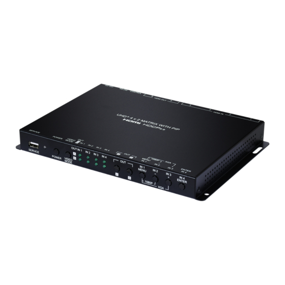
6. OPERATION CONTROLS AND FUNCTIONS 6.1 Front Panel IN 1 IN 2 IN 3 IN 4 IN 1 IN 2 IN 3 IN 4 MENU ENTER VIDEO 1080P SERVICE POWER MODE SERVICE Port: This port is reserved for firmware update and user EDID/ logo upload use only. - Page 9 Note: Pressing “MENU” and “+” together will reset the output resolution to XGA (1024×768@60Hz). Pressing “MENU” and “-” together will reset the output resolution to 1080p@60Hz. IN 2/- (MINUS) Button: When not in source selection mode, press to move down or adjust selections within OSD menus. When source selection is active, pressing this button will either select input 2 (Matrix mode) or sequentially switch through all 4 inputs for window 2 (PiP/PoP/ Quad/Preset modes).
-
Page 10: Rear Panel
6.2 Rear Panel HDMI IN HDMI OUT CONTROL RS-232 DC 24V HDMI IN 1~4 Ports: Connect to HDMI source equipment such as media players, game consoles, or set-top boxes. Note: Audio support on inputs 3~4 is limited to 2 channel LPCM. HDMI OUT A~B Ports: Connect to HDMI TVs, monitors, or amplifiers for digital video and audio output. -
Page 11: Rs-232 Pinout And Defaults
6.3 RS-232 Pinout and Defaults Serial Port Default Settings Baud Rate 19200 Data Bits Parity Bits None Stop Bits Flow Control None 3.5mm to DE-9 Adapter Cabl e... -
Page 12: Osd Menu
6.4 OSD Menu All functions of this unit can be controlled by using the OSD (On Screen Display) which is activated by pressing the MENU button on the front of the unit. Use the + (PLUS), − (MINUS), and ENTER buttons to navigate the OSD menu. - Page 13 Video Mode 2ND LEVEL 3RD LEVEL Video Mode Matrix QUAD Auto Preset 1 Preset 2 Preset 3 Preset 4 PiP/PoP/Quad/Preset Mode WIN 1 Source In 1~4 [1] WIN 2 Source In 1~4 [2] WIN 3 Source In 1~4 [3] WIN 4 Source In 1~4 [4] Auto Mode Auto Layout 2...
- Page 14 4) Fade In/Out: Enable or disable crossfading between sources in Matrix mode. 5) OUT A/B Source: Select the source for the specified HDMI output when in Matrix mode. Window Layout (Matrix Mode) 2ND LEVEL 3RD LEVEL Input Select In 1~4 [1] Aspect Ratio FULL 16:9...
- Page 15 Window Layout (Matrix Mode) 2ND LEVEL 3RD LEVEL Dark Cyan Gray Window Reset 1) Input Select: Select the input to modify. Note: All settings are individually saved, per-input. 2) Aspect Ratio: Select a fixed aspect ratio for the currently selected window.
- Page 16 Window Layout (PiP/PoP/Quad/Preset Modes) 2ND LEVEL 3RD LEVEL Priority 1~4 [4] Aspect Ratio FULL 16:9 16:10 Best Fit User Mirror Border On/Off Border Color Black GREEN Blue Yellow Magenta Cyan White Dark Red Dark Green Dark Blue Dark Yellow Dark Magenta Dark Cyan Gray Window Reset...
- Page 17 1) Window Select: Select the window to modify. Note: All settings are individually saved, per-window/per-mode. 2) Window On/Off: Enable or disable the currently selected window. 3) Position X/Y: Set the X and Y coordinate position of the upper left corner of the currently selected window.
- Page 18 Chroma Key (Matrix Mode Only) 2ND LEVEL 3RD LEVEL Chromakey User Select USER 1 User 2 User 3 User 4 White Yellow Cyan Green Magenta Blue Black Red Max 0~255 [255] Red Min 0~255 [0] Green Max 0~255 [255] Green Min 0~255 [0] Blue Max 0~255 [255]...
- Page 19 3) Red/Green/Blue Max/Min: Set the keying range (the color range within input 2’s video to make transparent) to use for the currently selected User Key Preset by setting the maximum and minimum values for red, green, and blue. Note: If a fixed preset is currently selected, the values will be displayed, but cannot be modified.
- Page 20 Audio (Matrix Mode) 2ND LEVEL 3RD LEVEL OUT A Source WINDOW In 1 In 2 In 3 In 4 OUT A Mute OUT B Source WINDOW In 1 In 2 In 3 In 4 OUT B Mute 1) OUT A Source: Select the audio source to pair with video output A. 2) OUT A Mute: Enable or disable muting audio output A.
- Page 21 Audio (PiP/PoP/Quad/Auto/Preset Modes) 2ND LEVEL 3RD LEVEL OUT A Source WIN 1 Win 2 Win 3 Win 4 In 1 In 2 In 3 In 4 OUT A Mute OUT B Source WIN 1 Win 2 Win 3 Win 4 In 1 In 2 In 3...
- Page 22 Input EDID 2ND LEVEL 3RD LEVEL EDID Mode Appoint All EDID FHD 2CH 4KUHD 2CH 4KUHD+ 2CH Sink OUT A Sink OUT B User 1 User 2 User 3 User 4 IN 1 EDID Same as [All EDID] IN 2 EDID Same as [All EDID] IN 3 EDID Same as [All EDID]...
- Page 23 3) In 1~4 EDID: Select the EDID to assign to the specified input. Note: Only available in the “Appoint” EDID Mode. 4) User 1~4 EDID: To update any of the unit’s 4 User EDIDs via USB, select “Yes” next to the appropriate User EDID and then insert a USB stick containing the new EDID into the Service port.
- Page 24 Output Resolution 2ND LEVEL 640×480p59 1920×1080p30 480p60 1920×1080p50 576p50 1920×1080P60 800×600p60 1920×1200RB 848×480p60 2048×1152RB 1024×768p60 3840×2160p24 1280×720p50 3840×2160p25 1280×720p60 3840×2160p30 1280×768p60 4K p24 (DCI) 1280×800p60 4K p25 (DCI) 1280×960p60 4K p30 (DCI) 1280×1024p60 4K p50 (DCI) 1360×768p60 4K p59 (DCI) 1366×768p60 4K p60 (DCI) 1400×1050p60...
- Page 25 OSD Settings 2ND LEVEL 3RD LEVEL Menu Position TOP LEFT Top Right Bottom Right Bottom Left Menu Timeout Off 5~60 [10] Info. Timeout Off 5~60 [5] Info. Display Off Transparency 1~10 Background Black GRAY Blue 1) Menu Position: Set the position of the OSD menu on the output. 2) Menu Timeout: Set the length of time, in seconds, that the OSD menu will continue to be displayed if there is no user input, or disable the timeout completely.
- Page 26 Logo Settings 2ND LEVEL 3RD LEVEL Logo On/Off Position X 0~100 [10] Position Y 0~100 [10] Load Default Logo Update Boot Logo On/Off Off Boot 4K Source DEFAULT User Boot 1080P Source DEFAULT User Boot VGA Source DEFAULT User User 4K Update User 1080P Update User VGA Update 1) Logo On/Off: Enable or disable displaying the logo graphic.
- Page 27 will be displayed on the OSD while the default logo is being installed. The unit will automatically reboot when it is finished. 4) Logo Update: To upload a graphic logo via USB, select “Yes” and then insert a USB stick containing the new logo graphic file (8-bit *.BMP format, 960×540 max resolution) into the Service port.
- Page 28 Ethernet 2ND LEVEL 3RD LEVEL IP Mode STATIC DHCP Static IP Config IP Address X.X.X.X [192.168.1.50] Subnet Mask X.X.X.X [255.255.255.0] Gateway X.X.X.X [192.168.1.254] Link Status IP Mode [Current IP Mode] IP Address Subnet Mask [Current Network Info] Gateway MAC Addr. [Unit’s MAC Address] 1) IP Mode: Set the unit’s IP address mode to Static or DHCP.
- Page 29 Preset 2ND LEVEL 3RD LEVEL Save PRESET 1 Preset 2 Preset 3 Preset 4 Recall PRESET 1 Preset 2 Preset 3 Preset 4 1) Save Preset 1~4: Select a preset and then press the “ENTER” button to store the unit’s current video window configuration to the currently selected preset.
- Page 30 Setup 2ND LEVEL 3RD LEVEL Firmware Update User EDID Reset Factory Reset User Boot Logo Clear 1) Auto Sync Off: Set the amount of time to continue outputting sync with a black screen if there are no live sources and no operations have been executed on the unit.
- Page 31 Information 2ND LEVEL 3RD LEVEL IN 1 IN 2 [Current Input Resolutions] IN 3 IN 4 [Current Output Resolution] Video Mode [Current Mode] Sink A Native [Native resolutions as reported by EDID] Sink B Native Firmware [Current Firmware Versions] RX3/RX4 Firmware 1) Information: Shows the currently detected details for all inputs and both outputs as well as listing the status of a few critical system settings and relevant firmware versions.
-
Page 32: Webgui Control
6.5 WebGUI Control • Device Discovery Please obtain the “Device Discovery” software from your authorized dealer and save it in a directory where you can easily find it. Connect the unit and your PC/Laptop to the same active network and execute the “Device Discovery”... - Page 33 • WebGUI Overview After connecting to the WebGUI’s address in a web browser, the login screen will appear. Please enter the appropriate user name and password then click “Submit” to log in. Note: The default user name and password is “admin”. On the left side of the browser you will see the following menu tabs where all primary functions of the unit are controllable via the built in WebGUI.
-
Page 34: Upper Tab Windows
6.5.1 Upper Tab Windows This upper section of the web interface is visible on every tab and provides control over the unit’s operational mode, source selection, and output resolution as well as containing basic information about the currently connected source and display devices. 1) Source: This section displays the currently detected resolution for the sources connected to each input. - Page 35 - Quad Mode: This is a quad-windowing preset mode. By default it is in an equal 4 window configuration but it can be manually adjusted by the user. - Auto Mode: This is a multi-windowing mode that automatically selects the number of visible windows (up to 4) based on the number of currently detected live inputs.
-
Page 36: Window Layout Tab
6.5.2 Window Layout Tab This tab provides control over the position, size, aspect, priority, and other settings of each window in multi-viewer modes. A graphical representation of the layout is also provided. When the unit is in the Matrix or Auto modes, only a limited selection of controls are available. - Page 37 5) Priority: Select the layer priority of the currently selected window. Priority 1 is at the front and priority 4 is at the back. Note: Not available in Matrix or Auto modes. 6) Aspect Ratio: Use the dropdown to select a fixed aspect ratio for the currently selected window or input.
-
Page 38: Picture Tab
6.5.3 Picture Tab This tab provides controls over each input’s contrast, brightness, saturation, hue, and sharpness levels. Note: All picture settings are per-input and are mode-independent. 1) Input Select: Use the dropdown to select the input to modify. 2) Reset: Reset the current input to its default settings. 3) Contrast: This slider provides control over the overall contrast of the currently selected source video. -
Page 39: Chroma Key Tab
6.5.4 Chroma Key Tab This tab provides control over the chroma key functions of the unit. A number of pre-designed standard key ranges are provided as well as slots to save up to 4 user-created key ranges. Keying values and ranges are set using the full RGB color space (0~255). -
Page 40: Audio Tab
6.5.5 Audio Tab This tab provides control over the audio output behavior of the unit, including routing selection and muting. Note: Due to Matrix mode only supporting a single “window”, changing modes between a multi-windowing mode and Matrix mode when an audio source is set to windows 2~4 will result in the source reverting to window 1. -
Page 41: Input Edid Tab
6.5.6 Input EDID Tab This unit provides the option of three standard EDIDs, two sink sourced EDIDs and four user uploaded EDIDs that can be assigned to all inputs at the same time, or to each input independently. Note: In most cases, assigning a new EDID to an input will cause the affected input to briefly blink out while the source adapts to the new information. -
Page 42: Hdcp Mode Tab
4) User 1~4 Update: To update any of the unit’s 4 User EDIDs, click the “Choose File” button to open the file selection window and then select the EDID file (*.bin format) located on your local PC. After selecting the file, click the “Update”... -
Page 43: Osd Settings Tab
6.5.8 OSD Settings Tab This tab provides control over the behavior of the OSD menu and informational display. 1) Menu Position: Use the dropdown to set the position of the OSD menu on the output. Available choices are: Top Left, Top Right, Bottom Right, and Bottom Left. -
Page 44: Logo Settings Tab
6.5.9 Logo Settings Tab This tab provides control over the user uploaded logo graphic. Controls include positioning, an uploading a new logo directly from the WebGUI and an option to reset the logo to a built in default image that can be used for testing. - Page 45 2) Boot Logo: Display: Enable or disable displaying the logo graphic. Reset: Removes all user uploaded boot logo images. Boot 4K Source: Select whether to display the default graphic image during boot, or the user uploaded graphic when the output resolution is set to 4K or above.
-
Page 46: Ethernet Tab
6.5.10 Ethernet Tab This tab provides controls to change the network settings for the unit. You can manually set the IP address, netmask and gateway address in “Static IP” mode, or you can obtain an IP address automatically by enabling DHCP. Note: The unit’s default Static IP address is 192.168.1.50. -
Page 47: Setup Tab
6.5.11 Setup Tab Provides a way to update firmware and reset various sections within the unit. Control over the unit’s Auto Sync Off feature, storing/recalling presets as well as configuring the WebGUI login settings is also provided here. 1) Preset Save: Select a preset from the dropdown list and then click the “Save”... -
Page 48: System Tab
7) Web Login Settings: WebGUI login settings can be set here. Username/Password: To change the login username and password, enter the new information in the spaces provided and press “Save”. Note: The default user name and password is “admin”. Timeout: Set the length of time to wait, in minutes, before logging out a user due to inactivity. -
Page 49: Telnet Control
6.6 Telnet Control Before attempting to use Telnet control, please ensure that both the unit and the PC are connected to the same active networks. Start your preferred Telnet/Console client, or use the built in client provided by most modern computer operating systems. After starting the client, connect by using the current IP address of the unit and port 23 (if the communication port number used by the unit has not been changed previously). - Page 50 COMMAND Description and Parameters get command ver Show the unit’s current command version. get mac addr Show the unit’s MAC address. get model name Show the unit’s model name. get model type Show the unit’s product type. set nickname N1 Set the unit’s nickname.
- Page 51 COMMAND Description and Parameters get power Show the unit’s current power state. set system reboot Reboot the unit. set ip mode N1 Set the IP address assignment mode. Available values for N1: STATIC [Static IP mode] DHCP [DHCP mode] get ip mode Show the current IP address assignment mode.
- Page 52 COMMAND Description and Parameters get static netmask Show the unit’s static netmask. set static gateway N1 Set the unit’s static IP address. N1 = X.X.X.X [X = 0~255, Gateway address] get static gateway Show the unit’s static gateway address. set webgui username N1 Set the WebGUI login username.
- Page 53 COMMAND Description and Parameters get telnet login Show the current state of Telnet login allowance. set telnet username N1 Set the Telnet login username. N1 = {Username} [16 characters max] get telnet username Show the current Telnet login username. set telnet password N1 Set the Telnet login password.
- Page 54 COMMAND Description and Parameters set window N1 route N2 Set the input to route to the specified window. N1 = 1~4 [Window number] N2 = 1~4 [Input port] Note: Valid in multi-windowing modes only. get window N1 route Show the input currently routed to the specified window. N1 = 1~4 [Window number] Note: Valid in multi-windowing modes only.
- Page 55 COMMAND Description and Parameters get window N1 mute Show the visibility status of the specified window, N1 = 1~4 [Window number] Note: Valid in multi-windowing modes only. set window N1 hposition N2 Set the horizontal position of the specified window. N1 = 1~4 [Window number] N2 = 0~{Max res}...
- Page 56 COMMAND Description and Parameters get window N1 hsize Show the current horizontal size of the specified window. N1 = 1~4 [Window number] Note: Valid in multi-windowing modes only. set window N1 vsize N2 Set the vertical size of the specified window. N1 = 1~4 [Window number] N2 = 1~{Max res}...
- Page 57 COMMAND Description and Parameters set window N1 aspect ratio N2 Set the aspect of the specified window. N1 = 1~4 [Window number] Available values for N2: [Full] [16:9] [16:10] [4:3] [Best Fit] [User] get window N1 aspect ratio Show the current aspect of the specified window. N1 = 1~4 [Window number] set window N1 mirror N2...
- Page 58 COMMAND Description and Parameters get window N1 border mode Show the current border mode of the specified window. N1 = 1~4 [Window number] set window N1 border color N2 Set the border color of the specified window. N1 = 1~4 [Window number] Available values for N2: [Black]...
- Page 59 COMMAND Description and Parameters set in N1 rotation mode N2 Enable or disable 90 degree rotation for the specified input. N1 = 1~4 [Input port] Available values for N2: [Rotation enabled] [Rotation disabled] get in N1 rotation mode Show the current rotation state of the specified input. N1 = 1~4 [Input port] set chroma key mode N1...
- Page 60 COMMAND Description and Parameters get chroma key rgb codes Show the currently selected chroma key RGB key range preset. set chroma key user N1 r max N2 Set the maximum red keying value for the specified user preset. N1 = 1~4 [User key preset number] N2 = 1~255 [Red key max value]...
- Page 61 COMMAND Description and Parameters set chroma key user N1 g min N2 Set the minimum green keying value for the specified user preset. N1 = 1~4 [User key preset number] N2 = 0~254 [Green key minimum value] get chroma key user N1 g min Show the current minimum green keying value saved in the specified user preset.
- Page 62 COMMAND Description and Parameters get in N1 contrast Show the current contrast level of the specified input. N1 = 1~4 [Input port] set in N1 brightness N2 Set the brightness level of the specified input. N1 = 1~4 [Input port] N2 = 0~100 [Brightness level] get in N1 brightness...
- Page 63 COMMAND Description and Parameters set in N1 h sharpness N2 Set the horizontal sharpness level of the specified input. N1 = 1~4 [Input port] N2 = 0~20 [Horizontal sharpness level] get in N1 h sharpness Show the current horizontal sharpness level of the specified input. N1 = 1~4 [Input port] set in N1 v sharpness N2...
- Page 64 COMMAND Description and Parameters set transition mode N1 Set the transition mode to use when switching sources in matrix mode. Available values for N1: [Cut transition] [Crossfade transition] get transition mode Show the current transition mode used when switching sources in matrix mode.
- Page 65 COMMAND Description and Parameters set all in edid N1 Set the EDID to use when the “All” EDID mode is active. Available values for N1: [1080p@60Hz, 2 channel audio] [4K@30Hz, 2 channel audio] [4K@60Hz, 2 channel audio] [User 1] [User 2] [User 3] [User 4] [Sink A]...
- Page 66 COMMAND Description and Parameters set in N1 hdcp mode N2 Set the HDCP behavior of the specified input. N1 = 1~4 [Input port] Available values for N2: [HDCP support disabled] [Refer to source] [Refer to display] get in N1 hdcp mode Show the current HDCP behavior used by the specified input.
- Page 67 COMMAND Description and Parameters set out A timing N1 Set the output resolution to use for both outputs. Available values for N1: [640×480p59] [480p60] [576p50] [800×600p60] [848×480p60] [1024×768p60] [1280×720p50] [1280×720p60] [1280×768p60] [1280×800p60] [1280×960p60] [1280×1024p60] [1360×768p60] [1366×768p60] [1400×1050p60] [1440×900p60] [1600×900p60rb] [1600×1200p60] [1680×1050p60] [1920×1080p24] [1920×1080p25]...
- Page 68 COMMAND Description and Parameters [3840×2160p59] [3840×2160p60] [3840×2400p60rb] [Native OUT A] [Native OUT B] get out A timing Show the current resolution used by both outputs. set out A osd banner location N1 Set the OSD menu location. Available values for N1: [Top Left] [Top Right] [Bottom Right]...
- Page 69 COMMAND Description and Parameters set out A osd info timeout N1 Set the OSD info’s timeout value (in seconds). Available values for N1: [Disabled] 5~60 [Timeout in seconds] get out A osd info timeout Show the current OSD info’s timeout value. set out A osd transparency level N1 Set the transparency level of the OSD.
- Page 70 COMMAND Description and Parameters set out A osd logo hposition N1 Set the horizontal position of the graphical logo overlay. N1 = 0~100 [Horizontal position] get out A osd logo hposition Show the current horizontal position of the graphical logo overlay. set out A osd logo vposition N1 Set the vertical position of the graphical logo overlay.
- Page 71 COMMAND Description and Parameters set out A auto sync off N1 Enable or disable the Auto Sync Off function and set the timeout length. Available values for N1: [Always on] [5 seconds] [10 seconds] [15 seconds] [30 seconds] [1 minutes] [1.5 minutes] [2 minutes] [2.5 minutes]...
-
Page 72: Connection Diagram
7. CONNECTION DIAGRAM Media Player/Game Console HDMI Input Media Player/Game Console HDMI Input Media Player/Game Console HDMI Input Media Player/Game Console HDMI Input HDMI IN HDMI OUT Power CONTROL RS-232 DC 24V Supply HDMI Output PC/Laptop HDMI Output HDMI TV/Display HDMI TV/Display... -
Page 73: Specifications
8. SPECIFICATIONS 8.1 Technical Specifications HDMI Bandwidth 18Gbps Input Ports 4×HDMI (Type-A) Output Ports 2×HDMI (Type-A) Control Ports 1×RS-232 (3.5mm) 1×IP Control (RJ-45) Service Port 1×USB 2.0 (Type-A) Baud Rate 19200 Power Supply 24V/2.7A DC (US/EU standards, CE/FCC/UL certified) ESD Protection (HBM) ±8kV (Air Discharge) ±4kV (Contact Discharge) Dimensions (W×H×D) -
Page 74: Video Specifications
8.2 Video Specifications Input Output Supported Resolutions (Hz) HDMI HDMI 720×400p@70/85 640×480p@60/72/75/85 59Hz 720×480i@60 720×480p@60 720×576i@50 720×576p@50 800×600p@56/60/72/75/85 60Hz 848×480p@60 1024×768p@60/70/75/85 60Hz 1152×864p@75 1280×720p@50/60 1280×768p@60/75/85 60Hz 1280×800p@60/75/85 60Hz 1280×960p@60/85 60Hz 1280×1024p@60/75/85 60Hz 1360×768p@60 1366×768p@60 1400×1050p@60 1440×900p@60/75 60Hz 1600×900p@60RB 1600×1200p@60 1680×1050p@60 1920×1080i@50/60 1920×1080p@24/25/30 1920×1080p@50/60... - Page 75 Input Output Supported Resolutions (Hz) HDMI HDMI 2560×1440p@60RB 2560×1600p@60RB 2048×1080p@24/25/30 2048×1080p@50/60 3840×2160p@24/25/30 3840×2160p@50/60 (4:2:0) 3840×2160p@24, HDR10 3840×2160p@50/60 (4:2:0),HDR10 3840×2160p@50/60 3840×2400@60RB 4096×2160p@24/25/30 4096×2160p@50/60 (4:2:0) 4096×2160p@24, HDR10 4096×2160p@50/60 (4:2:0),HDR10 4096×2160p@50/60...
-
Page 76: Audio Specifications
8.3 Audio Specifications 8.3.1 Digital Audio HDMI Inputs 1~2/ All Outputs LPCM Max Channels 8 Channels Sampling Rate (kHz) 32, 44.1, 48, 88.2, 96, 176.4, 192 Bitstream Supported Formats Standard & High-Definition HDMI Inputs 3~4 LPCM Max Channels 2 Channels Sampling Rate (kHz) Bitstream Supported Formats... -
Page 77: Cable Specifications
8.4 Cable Specifications 1080p 4K30 4K60 (4:4:4) (4:4:4) Cable Length 8-bit 12-bit 8-bit 8-bit High Speed HDMI Cable HDMI Input HDMI Output Bandwidth Category Examples: • 1080p (FHD Video) - Up to 1080p@60Hz, 12-bit color - Data rates lower than 5.3Gbps or below 225MHz TMDS clock •... -
Page 78: Acronyms
9. ACRONYMS ACRONYM COMPLETE TERM ASCII American Standard Code for Information Interchange Command-Line Interface DHCP Dynamic Host Configuration Protocol Digital Visual Interface EDID Extended Display Identification Data Gbps Gigabits per second Graphical User Interface HDCP High-bandwidth Digital Content Protection HDMI High-Definition Multimedia Interface HDTV High-Definition Television... - Page 79 ACRONYM COMPLETE TERM WUXGA (RB) Widescreen Ultra Extended Graphics Array (Reduced Blanking) Extended Graphics Array...
- Page 80 CYPRESS TECHNOLOGY CO., LTD. www.cypress.com.tw...
Need help?
Do you have a question about the CPLUS-V4H2HPIP and is the answer not in the manual?
Questions and answers