Table of Contents
Advertisement
Quick Links
Advertisement
Table of Contents

Related Manuals for Westermo Ibex-RT-630 Series


Summary of Contents for Westermo Ibex-RT-630 Series
- Page 1 Ibex-RT-630 Series EN 50155 LTE and WLAN Router...
-
Page 2: Table Of Contents
4.4. Connection of Cables ............22 4.5. Cooling ................23 4.6. Replacement of Product ............24 5. Specifications ................25 5.1. Interface Specifications ............25 5.2. Type Tests and Environmental Conditions ......... 31 6. Abbreviations and Terms ............... 33 Ibex-RT-630 Series... - Page 3 7. Revision Notes ................35 Ibex-RT-630 Series...
-
Page 4: General Information
Westermo reserves the right to revise this document or withdraw it at any time without prior notice. Under no circumstances shall Westermo be responsible for any loss of data or income or any special, incidental, and consequential or indirect damages howsoever caused. -
Page 5: Safety And Regulations
No personal injury Minor damage to the to avoid misuse of the product product, confusion or misunderstanding NOTICE Used for highlighting general, No personal injury Minor damage to the but important information product NOTE Table 1. Warning levels Ibex-RT-630 Series... -
Page 6: Safety Information
During installation, ensure a protective earthing conductor is first connected to the protective earthing terminal (only valid for metallic housings). Westermo recommends a cross-sectional area of at least 4 Upon removal of the product, ensure that the protective earthing conductor is disconnected last. -
Page 7: Care Recommendations
There may be a requirement on the minimum temperature rating of the cable to be connected to the field wiring terminals, see Interface Specifications. 2.3. Care Recommendations Follow the care recommendations below to maintain full operation of the product and to fulfill the warranty obligations: Ibex-RT-630 Series... -
Page 8: Product Disposal
If the product is not working properly, contact the place of purchase, the nearest Westermo distributor office or Westermo technical support. NOTE Devices not used shall be kept in the factory sealed moisture barrier bag. -
Page 9: Agency Approvals And Standards Compliance
• FCC-47-15, Radio frequency devices • FCC-47-22, Public mobile services • FCC-47-24, Personal communications services • FCC-47-27, Miscellaneous wireless communications services Safety • EN/IEC 62368-1, Safety Requirements for audio/video, information and communication technology equipment • EN 45545-2, Fire protection on railway vehicles Ibex-RT-630 Series... -
Page 10: United States - Fcc
The product has been tested according to AREMA Part 11.5.1 and 11.5.2 environmental class I and exposure class Internal. 2.5.4. Canada - IC This product complies with Industry Canada’s license-exempt RSSs. Operation is subject to the following two conditions: Ibex-RT-630 Series... -
Page 11: Simplified Declaration Of Conformity
This product contains the IC Certification numbers 9301A-103902DT50 (WLAN) and 10224A-201901EM12G (LTE). 2.5.5. Simplified Declaration of Conformity Hereby, Westermo declares that this product is in compliance with applicable EU directives and UK legislations. The full declaration of conformity and other detailed information is available at www.westermo.com/support/product-support. -
Page 12: Product Description
GNSS signals from GPS, Galileo, GLONASS or BeiDou systems. Figure 3. Ibex-RT-630-LV/Ibex-RT-630-HV block diagram The Westermo configuration management tool, WeConfig, can be used for discovery and basic configuration and maintenance. The configuration can be done via SNMP or via WebGUI. The status information is available in local LED status indicators, and through SNMP/WebGUI. -
Page 13: Available Models
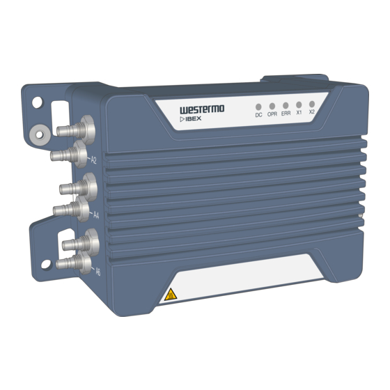
SIM card slot Gigabit Ethernet ports X1 and X2 Protective earth terminal Power input DC Frontside label Warning symbol for surface temperatures above +60°C Antenna ports A1 -A6 LED indicators Table 3. Location of interface ports and LED indicators Ibex-RT-630 Series... -
Page 14: Front Side Label
FCC / IC e-label: http://<ip-address> Default IP: 192.168.1.20 Type: Ibex-RT-xxx-xx EU IP66 Art. No: xxx-xxxxxx NPN: xxxxxx Max current: 0.6A Power: 24VDC (±30%) Westermo Neratec AG Country of origin: Switzerland Postfach 83, CH-8608 Bubikon Figure 4. Rear side label content Ibex-RT-630 Series... -
Page 15: Interface Ports View
Table 5. Interface ports view 3.4. Connector Information 3.4.1. Power Input Connection Marking Position Direction Description Positive terminal Negative terminal Housing Shield Chassis of product (ground) Table 6. M12 A-coded 4-pin male power connector according to IEC 61076-2-101 Ibex-RT-630 Series... -
Page 16: Sim Card Slot
To use the device in its specified temperature range it is important to use a robust industrial SIM card with extended temperature range. NOTICE In order to guarantee proper IP against dust and water, please check carefully that the drawer is fully inserted and screws are properly tightened. Ibex-RT-630 Series... -
Page 17: Ethernet Ports
Mbit/s, 100 Mbit/s and 1000 Mbit/s operation. Automatic MDI/MDIX crossover is supported for 10BASE-T, 100BASE-T, 1000BASE-T operation. Marking Position Direction Description X1/X2 In/Out In/Out In/Out In/Out In/Out In/Out In/Out In/Out Housing Shield Chassis of product (ground) Table 7. M12 X-coded 8-pin female Ethernet connector according to IEC 61076-2-109 Ibex-RT-630 Series... -
Page 18: Antenna Ports
A6 is used for the included GNSS receiver. The antenna port must be connected to an external GNSS antenna. NOTICE Any unused antenna ports must be properly terminated with 50 Ohm, otherwise the product might be damaged when power is applied to a non- terminated antenna port. Ibex-RT-630 Series... -
Page 19: Led Indicators
Operation status Error status Ethernet status for X1 port Ethernet status for X2 port Table 9. LED indicators NOTE Refer to management guide for detailed LED status indication. 3.6. Dimensions Dimensions are stated in mm and are regardless variants. Ibex-RT-630 Series... - Page 20 22.8 Ibex-RT-630-LV EU Power: 24VDC, 0.6A 3623-07500100001089 2012 111.4 Figure 7. Dimensional drawing Ibex-RT-630 Series...
-
Page 21: Installation
To reset the product into factory default settings, a reset adapter is needed which is plugged into one of the Ethernet ports X1 or X2 during startup. Art. no. Description 3623-0799 Factory Reset Plug, X-coded Factory reset procedure 1. Plug the factory reset adapter to one of the Ethernet interfaces. Ibex-RT-630 Series... -
Page 22: Earth Connection
When connecting the power cable, ensure that the pins are connected correctly before tightening the power cable to the unit. NOTE This product has no replaceable fuse and should be connected via an external fuse for protection. Ibex-RT-630 Series... -
Page 23: Cooling
When operating the product at high ambient temperatures, it is recommended to mount the product to a metallic base plate to improve the heat dissipation. The base plate increases the surface to spread the heat. Figure 11. Improved heat transfer based on fixing plate and natural convection Ibex-RT-630 Series... -
Page 24: Replacement Of Product
Be aware that the surface of this product may become hot. When it is operated at high temperatures, the external surface may exceed Touch Temperature Limit according to the product's relevant electrical safety standard. This product complies with Touch Temperature Limits throughout its operational temperature range. Ibex-RT-630 Series... -
Page 25: Specifications
Recommended external supply current capability for proper startup PoE (PoE powered product - Ibex-RT-630-LV only on X2) Connector M12 X-coded female Device mode A and B Rated voltage 48 VDC Operating voltage 37 to 57 VDC Power classification Class 3 Ibex-RT-630 Series... - Page 26 5.850 GHz Transmitting power Max. conducted combined transmit power within the whole frequency range: 1 port: BPSK...16QAM: 22 dBm, 64QAM: 20 dBm 2 ports: BPSK...16QAM: 25 dBm, 64QAM: 23 dBm 31 port: BPSK...16QAM: 27 dBm, 64QAM: 25 dBm Ibex-RT-630 Series...
- Page 27 NOTICE Depending on the installation country there are frequency/band restrictions and output power limitations. Ibex-RT-630 Series...
- Page 28 B41+B41; B66+B66 DL 3×CA / DL inter-band 3CA: B2+B4+B5; B2+B4+B13; B2+B5+B30; B2+B12+B30; B2+B29+B30; B3+B7+B20; B3+B7+B28; B3+B7+B8; B4+B5+B30; B4+B12+B30; B4+B29+B30; B5+B66+B2; B13+B66+B2; B66+B12+B30; B66+B29+B30; B66+B5+B30; B2+B14+B66 DL 3×CA / DL intra-band plus inter-band 3CA: B3+B3+B7; B3+B7+B7; B3+B3+B20; B3+B3+B28; B3+B3+B1; B4+B4+B5; Ibex-RT-630 Series...
- Page 29 QZSS: L1C/A, L1 SAIF GLONASS: L1OF BeiDou: B1I Galileo: E1B/C Supported GNSS constellations GPS+Galileo GPS+Galileo+GLONASS GPS+Galileo+BeiDou GPS+GLONASS GPS+BeiDou Galileo Galileo+GLONASS+BeiDou Galileo+BeiDou GLONASS GLONASS+BeiDou BeiDou Sample rate ≥ 10 Hz NOTICE Unused antenna port must be terminated with 50 Ohm terminations. Ibex-RT-630 Series...
- Page 30 NOTICE To avoid damages on the antenna interfaces, ensure that the far end side of the antenna cable and/or the antenna itself is connected to protective earth. NOTE External GNSS LNA is recommended to improve sensitivity. Ibex-RT-630 Series...
-
Page 31: Type Tests And Environmental Conditions
EN 50155 Power port (DC) > 100 MOhm to all other ports Dielectric strength EN 50155 Power port (DC) Ibex-RT-630-LV: 750 VDC, 60 s to all other ports Ibex-RT-630-HV: 2250 VDC, 60 s Table 10. EMC and electrical conditions Ibex-RT-630 Series... - Page 32 The power and Ethernet cables need to be fastened 200 mm or closer to the unit. The same recommendation applies to the Antenna cables. Provided all connectors are connected with IP66 cabling or fitted with protective caps (delivered with the unit) and tightened to the specified torque Table 11. Environmental and mechanical conditions Ibex-RT-630 Series...
-
Page 33: Abbreviations And Terms
Russian Global Positioning System US Global Positioning System High Voltage International Engineering Consortium Industry Canada Identification Input / Output Ingress Protection International Standardization Organisation Local Area Network Light Emitting Diode Long Term Evolution (4G) Standard for Wireless Broadband Communication Low Voltage Ibex-RT-630 Series... - Page 34 Subscriber Identity Module Serial Number SNMP Simple Network Management Protocol Virtual Private Network WebGUI Web Graphical User Interface WeConfig Westermo Configuration Tool WEEE Waste Electrical and Electronics Equipment WLAN Wireless Local Area Network Table 12. Abbreviations and terms Ibex-RT-630 Series...
- Page 35 3.5 Led Indicatiors; illustration added, 4.2 Factory Reset moved from old chapter 3.6, 4,5 Cooling; illustrations updated. Rev. C 2021-06 2.5.5 Europe – Simplified Declaration of Conformity updated text and figure Rev. B 2020-10 Updated frontpage Rev. A 2020-06 First revision Ibex-RT-630 Series...
- Page 36 Westermo • Metallverksgatan 6, SE-721 30 Västerås, Sweden Tel +46 16 42 80 00 Fax +46 16 42 80 01 E-mail: info@westermo.com www.westermo.com 6623-22905 REV. D 2021 10 Westermo Network Technologies AB, Sweden...
Need help?
Do you have a question about the Ibex-RT-630 Series and is the answer not in the manual?
Questions and answers