
Subscribe to Our Youtube Channel
Related Manuals for SEA LEPUS BOX 120V/24V


Summary of Contents for SEA LEPUS BOX 120V/24V
- Page 1 LEPUS BOX 120V/24V SEA USA Inc. 10850 N.W. 21st - unit 160 - DORAL - MIAMI Florida (FL) 33172 Phone: ++1-305.594.1151 Toll Free: 800.689.4716 www.sea-usa.com 67411870 REV. 03 - 10/2020...
- Page 2 IMPORTANT SAFETY INFORMATION GENERAL SAFETY PRECAUTIONS The following precautions are an integral and essential part of the product and must be supplied to the user Read them carefully as they contain important indications for the safe installation, use and maintenance. 1.
- Page 3 GENERAL SAFETY INFORMATION An appliance shall be provided with an instruction manual. The instruction manual shall give instructions for the installation, operation, and user maintenance of the appliance. The installation instructions shall specify the need for a grounding-type receptacle for connection to the supply and shall stress the importance of proper grounding.
- Page 4 The installer shall follow the provided instructions thoroughly. SEA products must only be used to automate doors, gates and wings. Any initiative taken without SEA USA Inc. explicit authorization will preserve the manufacturer from whatsoever responsibility.
- Page 5 5. The End of Type E. Type E (audible alarm) devices can no longer be used for entrapment protection. This change was made because the Type E device is really a warning device, not an entrapment-protection device. Also, all gate operator classes are now required to have an audio alarm that sounds when two successive obstructions are encountered via a contact-type system.
- Page 6 Over-Travel extremities of the rail to prevent the gate from Stop derailment (fig. 11). Important: For a higher security, SEA advices to install Over-Travel Stop infrared photocells Fig. 11...
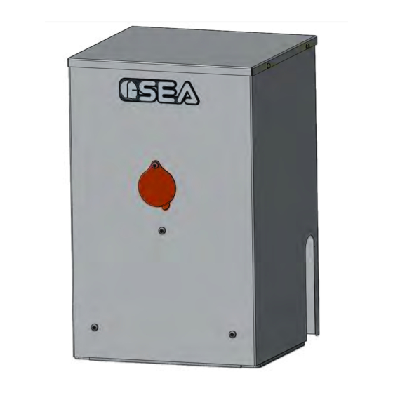
- Page 7 1. FEATURES AND SPECIFICATIONS LEPUS BOX is an electro-mechanical reduction operator. The LEPUS BOX can be supplied with either mechanical clutch or electronic sensing device as methods of limiting the motor torque. The gates open & close stop limits are accurately stored by mechanically triggering the on-board micro-switch. Manual release is quickly achieved by operating a key manual release system.The control unit allows to choose between automatic or semi-automatic control logic and will provide all normal safety logic functions COMPONENTS...
- Page 8 3. TYPICAL INSTALLATION 1) Operator 2) Concrete to build operator on 3) Photocells 4) Safety edge 5) Key switch 6) Travel gate stops 7) Radio receiver 8) Guide rollers 9) High speed ball bearing wheels 10) Warning notice inside 11) Warning notice outside Fig.
- Page 9 5.5. Follow the local building code to determine the required depth of the concrete pad. 5.6. SEA recommend the following pad measurements: Fig. 19 Red Head 3”...
- Page 10 7. CHAIN INSTALLATION In Fig. 22 and Fig. 23 it is possible to see the correct installation with open and closed gate respectively; notice the obliged run of the chain inside the pinion group which must not be modified. Open position Closed position Fig.
- Page 11 7.2. Install the chain making it pass through the pinion group as in Fig. 26. The chain must be always in line both vertically and orizontally, if not perfectly aligned (Fig. 27 and Fig. 28) it may derail from the pinion group or the motor reducer risks a greater effort not allowing the right operating of the system.
- Page 12 8. CLUTCH ADJUSTMENT 8.1. Unscrew the screw as in Fig. 29 8.2. Remove the carter as in Fig. 30 in order to act on the clutch with an hexagonal key. 8.3. Act on the «A» screw (Fig. 31) in the following way: - Clockwise = less clutch sensibility and more pushing force.
- Page 13 12. ANTENNA LEFT MOUNTING RIGHT MOUNTING Fig. 39 Fig. 42 Fig. 43 Fig. 40 Fig. 44 Fig. 41 Note: The antenna must be connected on the clamps 1 and 2 of the control unit CN1 connector; For further information on the antenna wiring diagram, please refer to the control unit user’s manual...
- Page 14 - Insert the hexagon «T» key and without forcing turn anti-clockwise until it stops (Fig. 35). - Slowly push the gate manually until the release is re-engaged. Caution: do not attempt to use the operator electrically before reconnecting the drive. SEA recommend to release the operator RELEASE only in case of power failure.
- Page 15 13. SINGLE PHASE POWER CONNECTION (120 V~ ) Sockets ON - OFF N = Neutral switch G = Ground P = Single Phase 120 V~ Fig. 45 120V ~ ½ HP POWER and DUAL 1 HP WIRE MOTOR Up to Up to 16 Gauge 150 FT...
- Page 16 NOTE: THE MANUFACTURER SHALL NOT SHOULDER ANY RESPONSIBILITIES IN CASE OF DAMAGE CAUSED BY NAPPROPRIATE, WRONG OR CARELESS USE SEA reserves the right to make all the necessary changes and modifications of the products or manuals without giving prior notice...
- Page 17 PAYMENT: Method of payments and terms are notified by SEA and displayed on the commercial invoice. DELIVERY: The delivery time on the invoice is not binding and represents an estimated delivery. Shipments costs will be charged to the buyer and SEA is not responsible for delays and/or damages occurred to the products during shipment.
- Page 18 NOTES...
- Page 20 SEA USA Inc. 10850 N.W. 21st - unit 160 - DORAL - MIAMI Florida (FL) 33172 Phone: ++1-305.594.1151 Toll Free: 800.689.4716 www.sea-usa.com sales@sea-usa.com...
Need help?
Do you have a question about the LEPUS BOX 120V/24V and is the answer not in the manual?
Questions and answers