Advertisement
Quick Links
SEA S.r.l.
DIREZIONE E STABILIMENTO:
Zona industriale 64020 S.ATTO Teramo - (ITALY)
Sistemi elettronici
Tel. 0861 588341 r.a. Fax 0861 588344
di Aperture Porte e Cancelli
GENERAL INFORMATION
The Vela barrier is an ideal solution for controlling traffic
movement in: private car parks, commercial premises,
hospitals, camp-sites etc.
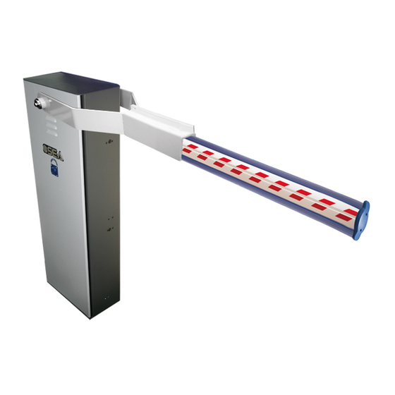
Fig. 1 shows the constituent parts of the Vela unit,
including the pedestal casing, electro-hydraulic
operator and counter sprung beam assembly.
The electro-hydraulic unit is made up of two parts:
- The anodised aluminium lower casing contains the
electric motor and hydraulic pump. The pump delivery
rate varies according to beam length. The electric motor
is totally immersed in oil. The oil acts as a coolant and
transmission medium.
- The upper part houses a piston jack that is coupled to a
rack and pinion drive assembly. The central distribution
flange contains the locking and pressure adjusting
device. The two pressure valves allow precise
adjustment of the working forces that are transmitted to
the aluminium beam.
The Vela operator incorporates a hydraulic locking
system that will hold and lock the beam in any position it
has been stopped.
An emergency release device allows to override the
locking system by using the personalised release key.
The barrier pedestal is manufactured of mild steel that
has been sprayed with high gloss resin paint treatment
resistant to atmospheric corrosion. The extruded
aluminium beam is supplied in a white powder coated
finish and fitted with reflective strips. A rubber nosing is
fitted along the bottom edge to prevent damage in case
of accidental contact.
The Vela barrier can be supplied with rigid aluminium
beams or with a factory fitted skirt.
The Vela is suitable for left hand or right hand
installations and is supplied complete with fitting
accessories.
The counterbalance spring diameter is selected using
the table below.
Cod. 67410035
INSTALLATION MANUAL
VELA
INSTALLATION INSTRUCTION FOR BARRIER AUTOMATION
Rev. 02 del 06/2000
http://www.seateam.com
e-mail:seacom@seateam.com (Uff. Comm.le)
seatec@seateam.com (Uff. Tecnico)
MOD. "VELA"
13 Key release
12 Spring
balance lever
11 Spring
15 Nut
6 Control
Unit
10 Fixing Nut
CE
14 Beam
1 Breather
screw
2 Limit Stops
3 Splined
shaft
4 filler
cap
5 oil sight
glass
7 Barrier
Pedestal
8 Ground
9 Mounting
Plate
Fig. 1
9/20
Advertisement

Related Manuals for SEA VELA


Summary of Contents for SEA VELA
- Page 1 INSTALLATION MANUAL VELA INSTALLATION INSTRUCTION FOR BARRIER AUTOMATION MOD. “VELA” GENERAL INFORMATION 14 Beam The Vela barrier is an ideal solution for controlling traffic movement in: private car parks, commercial premises, 1 Breather hospitals, camp-sites etc. screw 13 Key release Fig.
- Page 2 : 0,75 - 1 - 1,5 2 l. Drive torque : 0,76 daN/BAR Oil quantity : 1,2 l. Oil type : SEA OX SUPER Protection rating : IP. 55 Opening times : 3,8 s. (Pump 2 l.) : 5 s.
- Page 3 SEA S.r.l. http://www.seateam.com DIREZIONE E STABILIMENTO: e-mail:seacom@seateam.com (Uff. Comm.le) Zona industriale 64020 S.ATTO Teramo - (ITALY) Sistemi elettronici seatec@seateam.com (Uff. Tecnico) Tel. 0861 588341 r.a. Fax 0861 588344 di Aperture Porte e Cancelli MANUAL RELEASE The barrier is now in manual operational mode, so you can install and adjust the balance group, spring and beam.
- Page 4 LIMIT OF GUARANTEE The Vela operator is guaranteed for a period of 24 months. The guarantee period starts from the date stamp printed on the unit. The Vela guarantee will be void if the unit has been incorrectly installed, not used for the purpose intended, tampered with or modified in any way.
Need help?
Do you have a question about the VELA and is the answer not in the manual?
Questions and answers