Table of Contents
Advertisement
Quick Links
Advertisement
Table of Contents

Related Manuals for ETAS ES5352.1


Summary of Contents for ETAS ES5352.1
- Page 1 ES5352.1 Signal Conditioning Board User’s Guide...
- Page 2 The data in this document may not be altered or amended without special noti- fication from ETAS GmbH. ETAS GmbH undertakes no further obligation in rela- tion to this document. The software described in it can only be used if the customer is in possession of a general license agreement or single license.
-
Page 3: Table Of Contents
2.4.4 Inserting the ES5352.1 Signal Conditioning Board into a Slot..21 Configuration ..........22 2.5.1... - Page 4 6 ETAS Contact Addresses ........
-
Page 5: Introduction
Leave the plug-in board in its transport packaging until it is installed. Only remove, configure and install the ES5352.1 at a workplace that is protected against electrostatic discharges. This chapter contains information on the following topics: •... -
Page 6: Features
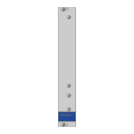
(example: PB1652LAMBDA.1-B Signal Conditioning for Lambda Sensor Simulation). Fig. 1-1 Front Panel and Plug-In Side of the ES5352.1 Signal Conditioning Board The function units of the ES5352.1 Signal Conditioning Board are shown in the following block diagram: DC/DC PB2_OUT1..15 DC/DC... - Page 7 To supply power to the piggybacks, up to four DC/DC converters can be installed per module on the ES5352.1 Signal Conditioning Board. These are either sup- plied with +5 V or +12 V from the backplane.
-
Page 8: Basic Safety Instructions
1.2.2 General Safety Information Please observe the Product Safety Notices ("ETAS Safety Notice") and the follow- ing safety notices to avoid health issues or damage to the device. Note The User's Guide must be read prior to the startup of the product! ETAS GmbH does not assume any liability for damages resulting from improper handling, unintended use or non-observance of the safety precautions. -
Page 9: Intended Use
1.2.4 Intended Use Application Area of the Product The ES5352.1 Signal Conditioning Board is a plug-in board for the ES5300.1-A Housing and the ES5300.1-B Housing for accommodating two modules for sig- nal conditioning. The ES5352.1 Signal Conditioning Board consists of: •... - Page 10 CAUTION! There is no protective circuitry for the inputs and outputs on the ES5352.1 Signal Conditioning Board! If required, the customer must provide this on the relevant piggyback. Power Supply The product is powered by the ES5300.1-A Housing or the ES5300.1-B Housing via the PCIe backplane connector.
- Page 11 To avoid damages to the hardware from electrostatic discharge, please observe the following precautionary measures: CAUTION! Some components of the ES5352.1 can be damaged or destroyed by electrostatic discharges. Leave the plug-in board in its transport pack- aging until it is installed.
- Page 12 To avoid injuries and hardware damages, please observe the following precau- tionary measures: • Do not apply any voltages to the connections of the ES5352.1 that do not correspond to the specifications of the respective connection. The exact specification of the I/O hardware is located in the manuals of the corre- sponding boards.
-
Page 13: Identifications On The Product
European Union The EU Directive 2002/95/EU limits the use of certain dangerous materials for electrical and electronic devices (RoHS conformity). ETAS confirms that the product corresponds to this directive which is applicable in the European Union. China ETAS confirms that the product meets the product-specific applicable guidelines... -
Page 14: Kc Marking
Introduction ETAS 1.3.3 KC Marking With the KC mark attached to the product and its packaging, ETAS confirms that the product has been registered in accordance with the product-specific KCC guidelines of the Republic of Korea. Product Return and Recycling... -
Page 15: Using This Manual
ETAS Introduction • "Technical Data and Norms" on page 35 This chapter contains the technical data on the ES5352.1 Signal Condi- tioning Board. In addition, fulfilled standards and norms are listed. 1.6.1 Using this Manual Representation of Information All activities to be carried out by the user are shown in what we call a "Use- Case"... - Page 16 A conversion between the file types Content markings and newly introduced logical and arithmetic is not possi- terms are shown in italics. ble. Important notes for the user are shown as follows: Note Important note for the user. ES5352.1 Signal Conditioning Board - User’s Guide...
-
Page 17: Features And Functions
Power Supply To supply the piggybacks with power, up to four DC/DC converters per module can be accommodated on the ES5352.1 Signal Conditioning Board. Their pri- mary function is voltage stabilization and galvanic isolation. The output voltages DC1 - DC4 of the converters are connected with the con- nector strip CO301 or C307 (see ""CO301"... -
Page 18: Fuses
I n p u t V o l t a g e o f t h e D C / D C C o n v e r t e r s " o n p a g e 2 2 ) . T h e TRACO POWER TEN 3 Series is one example of a usable type of DC/DC con- verter. Fuses There are four fuses on the ES5352.1 Signal Conditioning Board to protect the backplane voltages. FU204 FU201... -
Page 19: Assembly
• "Assembling the DC/DC Converters" on page 19 • "Assembling the Piggybacks" on page 20 • "Assembling the ES5352.1 Signal Conditioning Board in the ES5300.1-A Housing and in the ES5300.1-B Housing" on page 20 • "Inserting the ES5352.1 Signal Conditioning Board into a Slot"... -
Page 20: Assembling The Piggybacks
2.4.2 Assembling the Piggybacks Place the pin strips of the module onto the contact strips of the ES5352.1 Signal Conditioning Board so they correspond to each other, i.e. interrupted pin strip to interrupted contact strip and continuous pin strip to continuous contact strip. -
Page 21: Inserting The Es5352.1 Signal Conditioning Board Into A Slot
This can cause damage to or even destroy the boards to be installed. Make sure that the ES5352.1 with its piggybacks either adheres to the maximum width of 5 HP or that the neighboring slot is empty and that there are no assembled cover plates stopping the board from being inserted! 1. -
Page 22: Configuration
For system reasons, the plug-in boards and thus the piggybacks have consider- ably more power available to them via the +12V supply of the backplane (VCC12) than via the +5V supply (VCC5). The fuses on the ES5352.1 are dimen- sioned accordingly. -
Page 23: Configuring The I2C Addresses
ETAS Features and Functions Note Only one solder bridge can be installed because otherwise the +5 V and +12 V voltages are connected with each other and thus the fuses of the ES5352.1 break the circuit. 2.5.2 Configuring the I C Addresses The ES5352.1 supports a total of eight I... - Page 24 Slot 1 R307 R305 R303 R306 R304 R302 Address Slot 2 R315 R313 R311 R314 R312 R310 Assigned Assigned x = 0 Ω resistor must be assembled ES5352.1 Signal Conditioning Board - User’s Guide...
-
Page 25: Pin Assignment And Connections
ETAS Pin Assignment and Connections Pin Assignment and Connections This section describes the various connectors of the ES5352.1 Signal Condition- ing Board. • "Backplane Connector (CO200)" on page 25 • "D-Sub62 (CO100)" on page 27 • "Piggyback Connectors" on page 28 •... - Page 26 BN_4 BN_5 n.c. n.c. n.c. n.c. n.c. n.c. 12-Shield SPI_CS_A_n SPI_CS_B_n n.c. n.c. n.c. n.c. n.c. n.c. 11-Shield SPI_CLK SPI_MOSI n.c. n.c. n.c. n.c. n.c. n.c. 10-Shield SPI_MISO PCIE_WAKEn n.c. n.c. n.c. n.c. n.c. n.c. 9-Shield n.c. n.c. n.c. n.c. n.c.
-
Page 27: D-Sub62 (Co100)
PB2_OUT11 PB2_OUT12 PB2_OUT13 PB2_OUT14 PB2_OUT15 Housing at protective earth Tab. 3-1 "CO100" Pin Assignment Recommended Connectors The "Conec 163A16629X" connector with "Conec 165X10939X" housing is recommended for the connection with the D-Sub connector. ES5352.1 Signal Conditioning Board - User’s Guide... -
Page 28: Piggyback Connectors
PB1_IN9 PB1_IN8 PB1_IN7 PB1_IN6 PB1_IN5 PB1_IN4 PB1_IN3 PB1_IN2 PB1_IN1 n.c. PB1_OUT15 PB1_OUT14 PB1_OUT13 PB1_OUT12 PB1_OUT11 PB1_OUT10 PB1_OUT9 PB1_OUT8 PB1_OUT7 PB1_OUT6 PB1_OUT5 PB1_OUT4 PB1_OUT3 PB1_OUT2 PB1_OUT1 Tab. 3-2 Connections from "CO300" to SUB-D62 (CO100) ES5352.1 Signal Conditioning Board - User’s Guide... -
Page 29: Co301" Connector (Piggyback 1)
Note To avoid interference in the system, the backplane ground (GND) and the gal- vanically isolated piggyback grounds (PBx_DCn GND, x = slot 1 or 2, n = 1,2,3,4) should not be connected! ES5352.1 Signal Conditioning Board - User’s Guide... -
Page 30: Co306" Connector (Piggyback 2)
PB2_IN9 PB2_IN8 PB2_IN7 PB2_IN6 PB2_IN5 PB2_IN4 PB2_IN3 PB2_IN2 PB2_IN1 n.c. PB2_OUT15 PB2_OUT14 PB2_OUT13 PB2_OUT12 PB2_OUT11 PB2_OUT10 PB2_OUT9 PB2_OUT8 PB2_OUT7 PB2_OUT6 PB2_OUT5 PB2_OUT4 PB2_OUT3 PB2_OUT2 PB2_OUT1 Tab. 3-4 Connections from "CO306" to SUB-D62 (CO100) ES5352.1 Signal Conditioning Board - User’s Guide... -
Page 31: Co307" Connector (Piggyback 2)
Note To avoid interference in the system, the backplane ground (GND) and the gal- vanically isolated piggyback grounds (PBx_DCn GND, x = slot 1 or 2, n = 1,2,3,4) should not be connected! ES5352.1 Signal Conditioning Board - User’s Guide... -
Page 32: Connectors On The Board
Signal Signal BN_B_0 BN_B_1 BN_B_2 BN_B_3 BN_B_4 BN_B_5 Tab. 3-7 "CO102" Pin Assignment The "BN_B_n" signals are buffered by the driver modules TI 74LVTH16245. Each signal has a series resistance of 43.2 Ohm. ES5352.1 Signal Conditioning Board - User’s Guide... -
Page 33: C0103
Tab. 3-9 "CO105" Pin Assignment The I C signals "PCIE_SMBCLK" and "PCIE_SMBDAT" available at the CO105, CO301 and CO307 connectors go directly to the backplane and to the bus users on the boards. ES5352.1 Signal Conditioning Board - User’s Guide... - Page 34 Pin Assignment and Connections ETAS ES5352.1 Signal Conditioning Board - User’s Guide...
-
Page 35: Technical Data And Norms
ETAS Technical Data and Norms Technical Data and Norms This chapter contains the technical data on the ES5352.1 Signal Conditioning Board. In addition, fulfilled standards and norms are listed. Technical Data Voltages, Currents and Power Consumption Maximum voltage at inputs and outputs (CO100) -
Page 36: Fulfilled Standards And Norms
Technical Data and Norms ETAS Fulfilled Standards and Norms The ES5352.1 Signal Conditioning Board complies with the following standards and norms: Standard Testing EN 61326 Electrical equipment for measurement, control and labora- tory use EMC requirements EN 61000-6-2 Interference immunity (industrial environment) -
Page 37: Ordering Information
ETAS Ordering Information Ordering Information This chapter features the ordering information for the ES5352.1 Signal Condi- tioning Board as follows: Order Name Short Name Order Number Carrier Board for Signal Conditioning ES5352.1 F-00K-109-679 Circuits Scope of Supply Carrier Board for Signal Conditioning Circuits ES5352.1 Signal Conditioning Board - User’s Guide... - Page 38 Ordering Information ETAS ES5352.1 Signal Conditioning Board - User’s Guide...
-
Page 39: Etas Contact Addresses
Germany WWW: www.etas.com ETAS Subsidiaries and Technical Support For details of your local sales office as well as your local technical support team and product hotlines, take a look at the ETAS website: ETAS subsidiaries WWW: www.etas.com/en/contact.php ETAS technical support WWW: www.etas.com/en/hotlines.php... - Page 40 ETAS Contact Addresses ETAS ES5352.1 Signal Conditioning Board - User’s Guide...
-
Page 41: Index
Power supply for piggybacks 17 DC/DC converters configuring the input voltage 22 Qualification, required 8 Declarable Substances 14 Devices Connecting 12 Recycling 14 RoHS conformity China 13 ETAS Contact Addresses 39 European Union 13 ES5352.1 Signal Conditioning Board - User’s Guide... - Page 42 Safety instructions basic 8 Safety instructions, labeling of 8 safety precautions 8 Standards and norms 36 Technical data 35 Use, intended 9 Waste Electrical and Electronic Equip- ment 14 WEEE take-back system 14 ES5352.1 Signal Conditioning Board - User’s Guide...
Need help?
Do you have a question about the ES5352.1 and is the answer not in the manual?
Questions and answers