Table of Contents
Advertisement
Quick Links
Advertisement
Table of Contents

Related Manuals for ETAS ES1392.1


Summary of Contents for ETAS ES1392.1
- Page 1 ES1392.1 High Current Switch Board User’s Guide...
- Page 2 Copyright The data in this document may not be altered or amended without special notification from ETAS GmbH. ETAS GmbH undertakes no further obligation in relation to this document. The software described in it can only be used if the customer is in possession of a general license agreement or single license.
-
Page 3: Table Of Contents
Contents 1 Introduction ........... . . 5 Applications . - Page 4 6 ETAS Contact Addresses ........
-
Page 5: Introduction
The components, connectors and conductors of the ES1392.1 High Current Switch Board may carry dangerous voltages. These voltages may even exist when the ES1392.1 is not installed in the ES4100 or ES4300 or the ES4100 or ES4300 is powered off. -
Page 6: Features
Use of Two ES1392.1 High Current Switch Boards to Switch Two Battery Voltages The ES1392.1 High Current Switch Board does not have a VMEbus interface - it is controlled by TTL signals which have to be connected to a front-facing connector. - Page 7 • Maximum overall current of 40 A • Input voltage range of 6 - 60 V • Control connector on the front panel ("CTRL") (digital TTL signals) • Power supply input on the front panel • Overcurrent protection • Overcurrent status is routed to the "CTRL" status output on the front panel •...
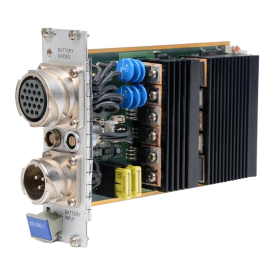
- Page 8 The following figure shows the front panel of the ES1392.1 High Current Switch Board. BATTERY NODES < BATTERY ES1392.1 INPUT Fig. 1-2 Front Panel of the ES1392.1 High Current Switch Board Introduction...
-
Page 9: Block Diagram
Block Diagram Fig. 1-3 shows the block diagram of the ES1392.1 High Current Switch Board. The battery voltages are supplied via "BATTERY INPUT". The battery nodes connected via "BATTERY NODES" can be switched to these battery voltages via the switches. - Page 10 Introduction...
-
Page 11: Hardware
"Protective Measures" on page 15 Functional Description The ES1392.1 High Current Switch Board has two groups of switch channels which differ in terms of their maximum current rating. Battery node 0 can be switched to either +UBatt or -UBatt whereas the other battery nodes can only be switched to +UBatt (see Tab. -
Page 12: Configuring Battery Node 0
Configuring Battery Node 0 Battery node 0 can be configured to be switched to either +UBatt or -UBatt. Once the configuration has been changed, both switches remain open until, after a delay, the new configuration becomes active. This makes it impossible to use battery node 0 as a half bridge for fast signals. -
Page 13: Controlling The Switches
For more details on protective measures, please refer to Section 2.12 on page 15. EEPROM The type of board (ES1392.1) and the version is stored in an EEPROM and can ® be read out via a 1-Wire interface on the "CTRL" connector by the ES1391.1 Power Supply Controller Board. -
Page 14: Battery Voltage At The "Ctrl" Connector
(MRC signal) is routed from the "BATTERY NODES" connector to the "CTRL" connector. The signal is protected (see section 2.12.3 on page 17). It is not used for any other purpose on the ES1392.1 High Current Switch Board. Reverse-Connect Protection of the Battery Node Switches The switches to +UBatt are protected against voltages at the battery node which are above the battery voltage. -
Page 15: Parallel Switching Of Several Battery Nodes
Parallel Switching of Several Battery Nodes To increase the maximum current of the battery nodes, the two 20-A battery nodes, BN0 and BN1, can be switched in parallel. The overcurrent protection of the switches to +UBatt of these two battery nodes is synchronized, i.e. they are both switched off (simultaneously) when an overcurrent is detected and then are both switched on again simultaneously. -
Page 16: Ubatt And -Ubatt At "Battery Nodes
The position of the fuses on the board is shown in Fig. 2-3 on page 16 - their specifications can be found in the following sections. FU 222 FU 270 FU 221 FU 271 FU 220 FU 272 Fig. 2-3 Position of the Fuses (Component Side) 2.12.1 +UBatt and -UBatt at "BATTERY NODES"... -
Page 17: Ubatt And -Ubatt At "Ctrl
2.12.2 +UBatt and -UBatt at "CTRL" The battery voltages output at the front-facing "CTRL" connector are pro- tected as follows: Fuse Specification Type Manufacturer/Order No. FU220 1 A, slow- NANO2 SMD Fuse Littelfuse 154.001T blowing FU221 1 A, slow- NANO2 SMD Fuse Littelfuse 154.001T blowing Tab. - Page 18 Fuse Specification Type Manufacturer/Order No. FU272 1.5 A NANO2 SMD Fuse Littelfuse 154.01.5T Fuse Protection of the +12 V Supply Voltage Tab. 2-10 Hardware...
-
Page 19: Pin Assignment
Pin Assignment This chapter explains the pin assignment of the connectors of the ES1392.1 High Current Switch Board. These are: • ""BATTERY NODES" Connector" on page 19 • ""BATTERY INPUT" Connector" on page 21 • ""CTRL" Connector" on page 21 •... - Page 20 Signal -UBatt -UBatt MRC signal in +UBatt +UBatt CH4 out CH4 out CH3 out CH2 out CH1 out CH0 out CH0 out -UBatt Not assigned +UBatt CH3 out CH2 out CH1 out Not assigned Tab. 3-1 "BATTERY NODES" Pin Assignment The counterpart connector is an"...
-
Page 21: Battery Input" Connector
"BATTERY INPUT" Connector Type: ITT Cannon CA02COM-E16-10PB Fig. 3-2 shows the pin assignment of the connector (view from the front). Fig. 3-2 "BATTERY INPUT" Connector Signal +UBatt -UBatt +UBatt Tab. 3-2 "BATTERY INPUT" Pin Assignment The counterpart connector is an "ITT Cannon CA06COM-E16-10SB". "CTRL"... -
Page 22: Supply" Connector
Signal switch error out +UBatt out -UBatt out Configuration switch 0 in MRC signal out Switch 0-4 ground ES1392.1 EEPROM signal ES1392.1 EEPROM ground Tab. 3-3 "CTRL" Pin Assignment The counterpart connector is a "Lemo FGG.1B.314.CLAD76". "SUPPLY" Connector Type: LEMO EGG.1B.307.CLL Fig. - Page 23 Signal -12 V Ground Not assigned +5 V Ground +12 V Not assigned Tab. 3-4 "SUPPLY" Pin Assignment The counterpart connector is a "Lemo FGG.1B.307.CLAD76". Pin Assignment...
- Page 24 Pin Assignment...
-
Page 25: Accessories
Accessories Cables To connect the ES1392.1 High Current Switch Board to the Power Supply and to the Controller Board two cables are required, which are described below. 4.1.1 Cable CBAV300.1-2: Connection between ES1392.1 and Power Supply (Battery Voltages) Product Data Short description CBAV300.1-2... - Page 26 (14mc - 14mc, 0.5m) Product part number F 00K 103 217 Specification Length 0.5 m Type 14 wires Connectors To ES1392.1 Lemo FGG.1B.314.CLAD76 (plug, solder version) To ES1391.1 Lemo FGG.1B.314.CLAD76 (plug, solder version) Function ES1391.1 LEMO ES1392.1 LEMO FGG Connector...
- Page 27 Function ES1391.1 LEMO ES1392.1 LEMO FGG Connector FGG Connector Switch 0-4 ground ES1392.1 EEPROM signal ES1392.1 EEPROM ground Front panel Front panel Accessories...
- Page 28 Accessories...
-
Page 29: Technical Data
Technical Data This chapter contains the technical data on the ES1392.1 High Current Switch Board. Battery Inputs Input voltage range 6 - 60 V Input current Max. 40 A High Current Switches Overcurrent protection Automatic recovery after overcurrent detection > 500 ms, < 800 ms (periodically) Settling time <... - Page 30 High Current Switch Interface Configuration 1 interface Digital output channels Digital output level TTL (0/5 V) Maximum digital output current 10 mA Digital input channels Digital input level TTL (0/5 V) Digital input current < 100 µA (I ), < -1 µA (I Digital galvanic isolation Digital overvoltage protection Yes (60 V)
- Page 31 Power Supply Power consumption +5 V DC ± 5 %, 300 mA max. ±12 V DC -5% .. ±15 V +5%, 50 mA max. Dimensions Height Width 8 HP (occupies 2 VME slots) Technical Data...
- Page 32 Technical Data...
-
Page 33: Etas Contact Addresses
Germany WWW: www.etas.de ETAS Subsidiaries and Technical Support For details of your local sales office as well as your local technical support team and product hotlines, take a look at the ETAS website: ETAS subsidiaries WWW: www.etas.com/en/contact.php ETAS technical support WWW: www.etas.com/en/hotlines.php... - Page 34 ETAS Contact Addresses...
- Page 35 15 Block diagram 9 Introduction 5 Cables 25 Configuration MRC signal 14 battery node 0 12 Overcurrent protection 13 EEPROM status output 13 for version data 13 ETAS Contact Addresses 33 Parallel switching several battery nodes 15 Index...
- Page 36 Pin assignment 19 "BATTERY INPUT" 21 "BATTERY NODES" 19 "CTRL" 21 "SUPPLY" 22 Potential difference between ground and -UBatt 15 Protective measures 15 Reverse-connect protection 14 Switch control 13 Switching possibilities 11 Technical data 29 Index...
Need help?
Do you have a question about the ES1392.1 and is the answer not in the manual?
Questions and answers