
Related Manuals for Satel OPAL Plus


Summary of Contents for Satel OPAL Plus
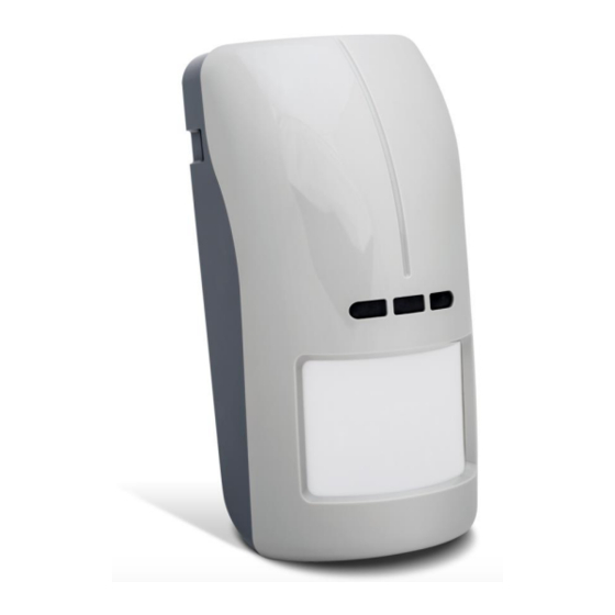
- Page 1 OPAL Plus Outdoor dual technology motion detector Firmware version 3.00 opal_plus_en 03/21 SATEL sp. z o.o. • ul. Budowlanych 66 • 80-298 Gdańsk • POLAND tel. +48 58 320 94 00 www.satel.eu...
- Page 2 Changes, modifications or repairs not authorized by the manufacturer shall void your rights under the warranty. SATEL aims to continually improve the quality of its products, which may result in changes in their technical specifications and software. Current information about the changes being introduced is available on our website.
-
Page 3: Table Of Contents
CONTENTS Features ........................... 2 Description ........................2 Anti-mask feature ......................2 Dusk sensor ........................2 Supervision features ......................3 LED indicators ........................3 Remote configuration mode enable / disable ..............4 Electronics module ......................4 Installation ........................5 Wall mounting ........................8 Angle bracket mounting .................... -
Page 4: Features
OPAL Plus SATEL The OPAL Plus detector detects motion in the protected area. It is designed for outdoor use. This manual applies to the detector with electronics version D. The detector meets the requirements of the EN 50131-2-4 standard for Grade 2. -
Page 5: Supervision Features
SATEL OPAL Plus accidental changes of light intensity. Table 1 presents light intensity values for three out of sixteen programmable detection thresholds of the sensor (see “Configuring the detector”). Light intensity Detection Turning on [P Turning off [P threshold minimum... -
Page 6: Remote Configuration Mode Enable / Disable
OPAL Plus SATEL Enabling the LEDs by using a jumper If you put a jumper across the LED pins, the LEDs will be enabled, i.e. they will indicate the events described above (the LED indicators can’t be enabled / disabled remotely). If you do not put a jumper across the pins, the LEDs will be disabled, but they can be enabled / disabled remotely. -
Page 7: Installation
LED. yellow LED. infrared receiver allowing to configure the detector by means of OPT-1 keyfob. The keyfob is offered by SATEL. buttons used during sensors sensitivity setting. MODE button used for the detector configuration (see: “Configuring the detector”). PIR sensor (dual element pyrosensor). - Page 8 OPAL Plus SATEL Install the detector at the recommended height (Fig. 3-I). If traffic nearby or objects moving out of the protected area cause an alarm, move the detector slightly downwards or reduce the detector sensitivity (Fig. 3-II).
- Page 9 SATEL OPAL Plus 3. Make the opening for cable in the enclosure base. 4. Mount the enclosure base to the wall (see: “Wall mounting”), to the angle bracket (see: “Angle bracket mounting”) or to the ball bracket (see: “Ball bracket mounting”). In Figure 6 possible ways of mounting the detector are shown.
-
Page 10: Wall Mounting
OPAL Plus SATEL Wall mounting 1. Run the cable through the opening in the enclosure base. 2. Using wall plugs (screw anchors) and screws, fasten the enclosure base to the wall. Angle bracket mounting 1. Attach extra tamper switch: – screw the holder to the tamper switch (Fig. 7-I), –... -
Page 11: Ball Bracket Mounting
SATEL OPAL Plus Ball bracket mounting 1. Attach extra tamper switch: – screw the holder to the tamper switch (Fig. 8-I), – put the unit making the surface bigger on the tamper switch (Fig. 8-II), – screw the tamper unit to the ball bracket (Fig. 8-IV). - Page 12 OPAL Plus SATEL...
-
Page 13: Connecting The Additional Tamper Switch
SATEL OPAL Plus Connecting the additional tamper switch The additional tamper switch is provided with three wires: black – common wire, blue – wire for NC circuit, grey – wire for NO circuit. The tamper switch can be connected in series to the detector tamper output (TMP) or to additional tamper circuit. -
Page 14: Configuring By Means Of The Detector Buttons
LED will indicate which sensor is being configured (see: “Signaling in the configuration mode”). Configuring by means of OPT-1 keyfob The OPT-1 keyfob is available in SATEL’s product range. Point the keyfob towards the detector and by pressing buttons (value decreasing) and (value increasing) set the sensitivity / detection threshold of the sensor. -
Page 15: Separate Testing Of Sensors
SATEL OPAL Plus Separate testing of sensors Testing of the sensors is done in the detector configuration mode. Starting the mode, choosing the sensor and the way of changing sensitivity are described in detail in the chapter “Configuring the detector”. - Page 16 OPAL Plus SATEL Microwave frequency ..................... 24 GHz Detectable speed ...................... 0.3...3 m/s Alarm signaling period......................2 s Warm-up period ........................40 s Recommended installation height ..................2.4 m Security grade according to EN 50131-2-4 ..............Grade 2 Standards complied with ......EN50131-1, EN 50131-2-4, EN50130-4, EN50130-5 IP code ..........................IP54...
Need help?
Do you have a question about the OPAL Plus and is the answer not in the manual?
Questions and answers