
Related Manuals for Satel OPAL


Summary of Contents for Satel OPAL
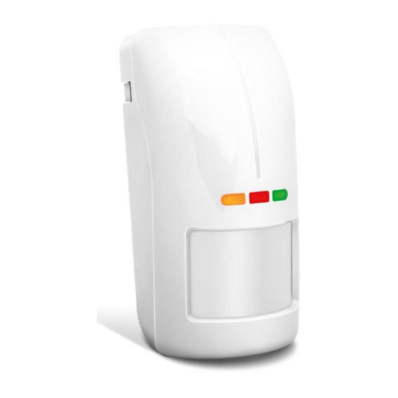
- Page 1 OPAL Outdoor dual technology motion detector Firmware version 3.00 opal_en 03/21 SATEL sp. z o.o. • ul. Budowlanych 66 • 80-298 Gdańsk • POLAND tel. +48 58 320 94 00 www.satel.eu...
- Page 2 Changes, modifications or repairs not authorized by the manufacturer shall void your rights under the warranty. SATEL aims to continually improve the quality of its products, which may result in changes in their technical specifications and software. Current information about the changes being introduced is available on our website.
-
Page 3: Table Of Contents
CONTENTS Features ........................... 2 Description ........................2 Anti-mask feature ......................2 Supervision features ......................2 LED indicators ........................3 Remote configuration mode enable/disable ..............3 Electronics module ......................3 Installation ........................5 Wall mounting ........................7 Angle bracket mounting ....................7 Ball bracket mounting ....................... -
Page 4: Features
OPAL SATEL The OPAL detector detects motion in the protected area. It is designed for outdoor use. This manual applies to the detector with electronics version D. The detector meets the requirements of the EN 50131-2-4 standard for Grade 2. -
Page 5: Led Indicators
SATEL OPAL LED indicators The LEDs indicate: warm-up – all LEDs flashing alternately for about 40 seconds; motion detected by microwave sensor – green LED ON for 4 seconds; motion detected by PIR sensor – yellow LED ON for 4 seconds;... - Page 6 OPAL SATEL terminals: - anti-mask output (NC relay). TMP - tamper output (NC). - alarm output (NC relay). COM - common ground. +12V - power input. LED - remote LED control. SVCE - remote control of configuration mode. - terminal not used.
-
Page 7: Installation
SATEL OPAL 4. Installation Disconnect power before making any electrical connections. If the detector is to be pet immune, it should be mounted at 2.4 m height with no vertical tilt. It is especially important when mounting on a ball bracket. - Page 8 OPAL SATEL 3. Make the opening for cable in the enclosure base. 4. Mount the enclosure base to the wall (see: “Wall mounting”), to the angle bracket (see: “Angle bracket mounting”) or to the ball bracket (see: “Ball bracket mounting”).
-
Page 9: Wall Mounting
SATEL OPAL Wall mounting 1. Run the cable through the opening in the enclosure base. 2. Using wall plugs (screw anchors) and screws, fasten the enclosure base to the wall. Angle bracket mounting 1. Attach extra tamper switch: – screw the holder to the tamper switch (Fig. 6-I), –... -
Page 10: Ball Bracket Mounting
OPAL SATEL Ball bracket mounting 1. Attach extra tamper switch: – screw the holder to the tamper switch (Fig. 7-I), – put the unit making the surface bigger on the tamper switch (Fig. 7-II), – screw the tamper unit to the ball bracket (Fig. 7-IV). - Page 11 SATEL OPAL...
-
Page 12: Connecting The Additional Tamper Switch
OPAL SATEL Connecting the additional tamper switch The additional tamper switch is provided with three wires: black – common wire, blue – wire for NC circuit, grey – wire for NO circuit. The tamper switch can be connected in series to the detector tamper output (TMP) or to additional tamper circuit. -
Page 13: Ending Configuration Mode
SATEL OPAL Press the MODE button briefly in order to proceed and configure another sensor. Blinking of the proper LED will indicate which sensor is being configured (see: “Signaling in the configuration mode”). Ending configuration mode Press the detector MODE button for 2 seconds or remove the common ground from the SVCE terminal. -
Page 14: Specifications
OPAL SATEL 3. Check that moving in the coverage area will make the violation signaling LED light up. 4. If it is needed, readjust sensitivity and check the sensor operating. 7. Specifications Supply voltage ....................12 VDC ±15% Standby current consumption ..................12 mA Maximum current consumption ..................
Need help?
Do you have a question about the OPAL and is the answer not in the manual?
Questions and answers