
Related Manuals for Satel SLIM-PIR-PRO


Summary of Contents for Satel SLIM-PIR-PRO
- Page 1 SLIM-PIR-PRO Digital passive infrared detector with anti-mask Firmware version 1.00 slim-pir-pro_en 05/20 SATEL sp. z o.o. • ul. Budowlanych 66 • 80-298 Gdańsk • POLAND tel. +48 58 320 94 00 www.satel.eu...
- Page 2 Changes, modifications or repairs not authorized by the manufacturer shall void your rights under the warranty. SATEL aims to continually improve the quality of its products, which may result in changes in their technical specifications and software. Current information about the changes being introduced is available on our website.
-
Page 3: Table Of Contents
CONTENTS Features ........................... 2 Description ........................2 Active IR anti-mask ......................2 Supervision features ......................3 LED indicators ........................3 Remote configuration mode enable/disable ..............3 Electronics module ......................3 Terminal block ........................5 Selecting a mounting location ................... 6 Installation ........................ -
Page 4: Features
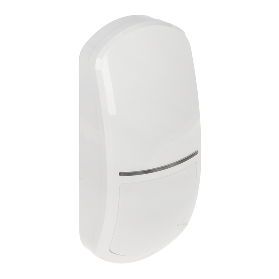
SLIM-PIR-PRO SATEL The SLIM-PIR-PRO detector detects movement in the protected area. This manual applies to the detector with electronics version D. The detector meets requirements of the EN 50131-2-2 standard for Grade 3. 1. Features Motion detection with passive infrared sensor (PIR). -
Page 5: Supervision Features
SATEL SLIM-PIR-PRO Supervision features In the event of the voltage drop below 9 V (±5%) for more than 2 seconds or the motion detection system failure, the detector will signal a trouble. The trouble is indicated by the alarm output activation and the LED indicators coming on. Signaling will continue as long as the trouble exists. - Page 6 Fig. 14 (mounting on bracket). infrared receiver allowing to configure the detector by means of OPT-1 keyfob. The keyfob is available in SATEL's product range. MODE button used for configuring the detector (see “Configuring the detector”). tamper switch activated by cover removal.
-
Page 7: Terminal Block
SATEL SLIM-PIR-PRO 4. Terminal block The terminal block is located on the enclosure base (Fig. 6). To get access to the terminals, you must remove the electronics module (Fig. 8). - anti-mask output (NC relay). - tamper output (NC relay). -
Page 8: Selecting A Mounting Location
SLIM-PIR-PRO SATEL 5. Selecting a mounting location Do not install the detector outdoors (A). Install the detector at the recommended height (B). The detector installed at the recommended height meets requirements of the EN 50131-2-2 standard for Grade 3. -
Page 9: Installation
SATEL SLIM-PIR-PRO 6. Installation Disconnect power before making any electrical connections. 1. Remove the front cover (Fig. 7). 2. Move the electronics module down to unlock it, and then remove it from the enclosure base (Fig. 8). 3. Make the openings for screws (Fig. 9 or Fig. 10) and cable (Fig. 11) in the enclosure base. - Page 10 SLIM-PIR-PRO SATEL 6. Connect the wires to the corresponding terminals. If the detector is mounted on the bracket, connect the tamper switch in series with the detector tamper output. The way of connecting the tamper switch is shown in Fig. 14 (NC configuration), Fig. 16 (2EOL configuration) and Fig.
- Page 11 SATEL SLIM-PIR-PRO...
- Page 12 SLIM-PIR-PRO SATEL...
-
Page 13: Configuring The Detector
To configure the detector, you can use the buttons on the electronics module or the OPT-1 keyfob. The OPT-1 keyfob is available in SATEL's product range. Starting configuration mode Press the MODE button on the detector electronics module for 3 seconds or connect the SRVC terminal to common ground. -
Page 14: Running Functions And Configuring Parameters
SLIM-PIR-PRO SATEL Running functions and configuring parameters 1. Use the buttons on the electronics module ( - next function; - previous function) or the keyfob keys ( - next function; - previous function) to find a function you want to run. -
Page 15: Ending Configuration Mode
SATEL SLIM-PIR-PRO Ending configuration mode Press the MODE button on the electronics module for 3 seconds or disconnect the SRVC terminal from common ground. If you started the configuration mode by using the MODE button, the configuration mode will be ended automatically 20 minutes after the last operation performed by the user. -
Page 16: Specifications
2.4 m. Figure 19 shows the coverage area of the SLIM-PIR-PRO detector with a wide-angle lens (WD), which is installed in the detector by default. You can use the enclosure cover with another lens.
Need help?
Do you have a question about the SLIM-PIR-PRO and is the answer not in the manual?
Questions and answers