
Related Manuals for Satel OPAL Pro


Summary of Contents for Satel OPAL Pro
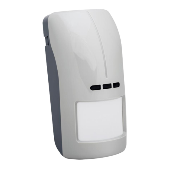
- Page 1 OPAL Pro Outdoor dual technology motion detector Firmware version 2.00 opal_pro_en 03/21 SATEL sp. z o.o. • ul. Budowlanych 66 • 80-298 Gdańsk • POLAND tel. +48 58 320 94 00 www.satel.eu...
- Page 2 Changes, modifications or repairs not authorized by the manufacturer shall void your rights under the warranty. SATEL aims to continually improve the quality of its products, which may result in changes in their technical specifications and software. Current information about the changes being introduced is available on our website.
-
Page 3: Table Of Contents
CONTENTS Features ........................... 2 Description ........................2 Active IR anti-mask ......................2 Dusk sensor ........................3 Supervision features ......................3 LED indicators ........................3 Remote configuration mode enable / disable ..............4 Electronics module ......................4 Installation ........................5 Wall mounting ........................8 Angle bracket mounting .................... -
Page 4: Features
OPAL Pro SATEL The OPAL Pro detector detects motion in the protected area. It is designed for outdoor use. This manual applies to the detector with electronics version D. The detector meets requirements of the EN 50131-2-4 standard for Grade 3. -
Page 5: Dusk Sensor
SATEL OPAL Pro Dusk sensor Figure 1 shows the way the dusk sensor operates. On the timeline the T time delay is presented (in operating mode T=3 min, in configuration mode T=3 s). Illustrated with the letter H light intensity hysteresis and time delay make the sensor immune to short and accidental changes of light intensity. -
Page 6: Remote Configuration Mode Enable / Disable
OPAL Pro SATEL Enabling the LEDs by using a jumper If you put a jumper across the LED pins, the LEDs will be enabled, i.e. they will indicate the events described above (the LED indicators can’t be enabled / disabled remotely). If you do not put a jumper across the pins, the LEDs will be disabled, but they can be enabled / disabled remotely. -
Page 7: Installation
LED. yellow LED. infrared receiver allowing to configure the detector by means of OPT-1 keyfob. The keyfob is offered by SATEL. anti-mask circuit LEDs. buttons used during sensors sensitivity setting. MODE button used for the detector configuration (see: “Configuring the detector”). - Page 8 OPAL Pro SATEL The detector can be installed outdoors as well as indoors, in spaces with harsh environmental conditions (high dustiness, high humidity, low or high temperatures, etc.). Thus, you can use it in warehouses, production halls, or other industrial facilities.
- Page 9 SATEL OPAL Pro 3. Make the opening for cable in the enclosure base. 4. Mount the enclosure base to the wall (see: “Wall mounting”), to the angle bracket (see: “Angle bracket mounting”) or to the ball bracket (see: “Ball bracket mounting”).
-
Page 10: Wall Mounting
OPAL Pro SATEL 5. Fasten the electronics module in the enclosure base. 6. Connect the wires to the corresponding terminals. If the detector is to be installed outdoors, do not connect the anti-mask outputs to the control panel zones. Severe weather conditions, including rain, fog or frost, can be interpreted by the anti-mask circuit as an attempt to mask the detector. -
Page 11: Ball Bracket Mounting
SATEL OPAL Pro Ball bracket mounting 1. Attach extra tamper switch: – screw the holder to the tamper switch (Fig. 8-I), – put the unit making the surface bigger on the tamper switch (Fig. 8-II), – screw the tamper unit to the ball bracket (Fig. 8-IV). - Page 12 OPAL Pro SATEL...
-
Page 13: Connecting The Additional Tamper Switch
SATEL OPAL Pro Connecting the additional tamper switch The additional tamper switch is provided with three wires: – black – common wire, – blue – wire for NC circuit, – grey – wire for NO circuit. The tamper switch can be connected in series to the detector tamper output (TMP) or to additional tamper circuit. -
Page 14: Configuring By Means Of The Detector Buttons
LED will indicate which sensor is being configured (see: “Signaling in the configuration mode”). Configuring by means of OPT-1 keyfob The OPT-1 keyfob is available in SATEL’s product range. Point the keyfob towards the detector and by pressing buttons (value decreasing) and (value increasing) set the sensitivity / detection threshold of the sensor. -
Page 15: Walk Test
SATEL OPAL Pro 7. Walk test Check that moving within the coverage area will make the LED light up red. Figure 9 shows the coverage areas of the motion detector (a - minimum, b - default, c - maximum, d - creep zone). - Page 16 OPAL Pro SATEL D/N dusk sensor (OC type output) ............... 50 mA / 12 VDC Relay contact resistance alarm output ........................34 Ω anti-mask output ......................34 Ω Microwave frequency ..................... 24 GHz Detectable speed ...................... 0.2...3 m/s Alarm signaling period......................2 s Warm-up period ........................
Need help?
Do you have a question about the OPAL Pro and is the answer not in the manual?
Questions and answers