
Related Manuals for Satel GREY


Summary of Contents for Satel GREY
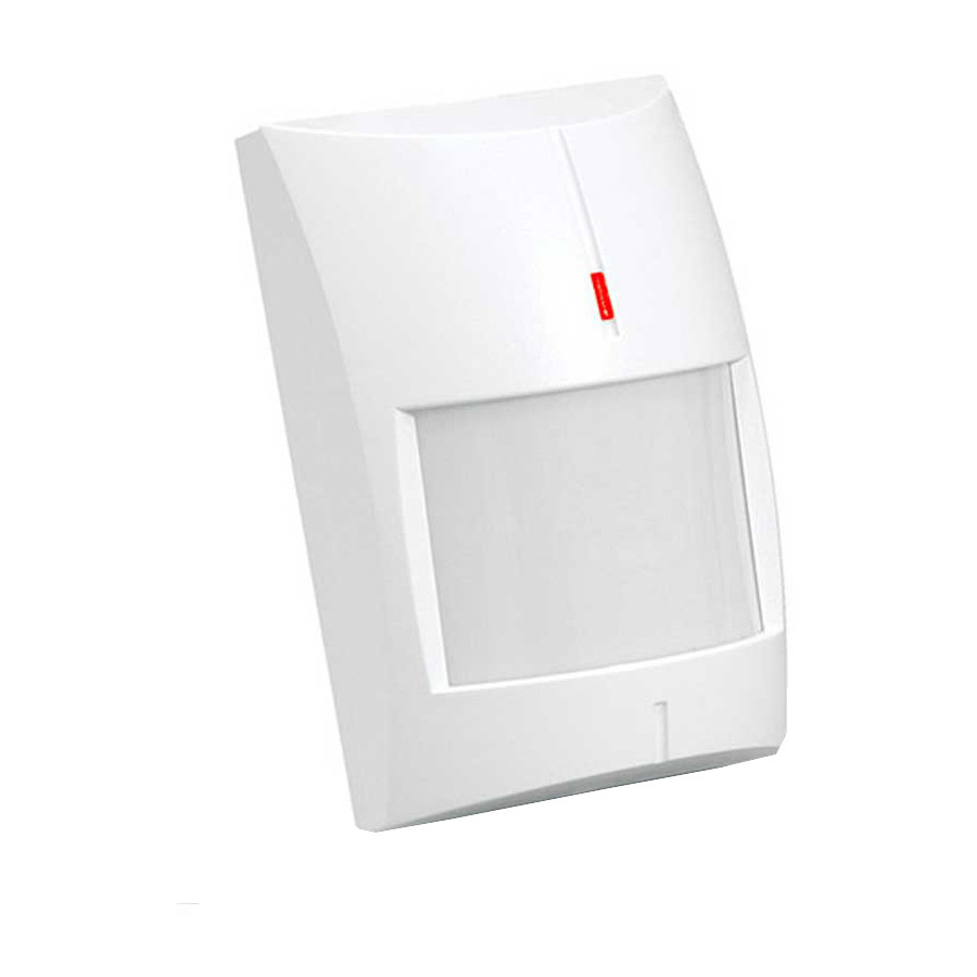
- Page 1 GREY / GREY Plus Digital dual technology motion detector Firmware version 1.3 grey_en 06/21 SATEL sp. z o.o. • ul. Budowlanych 66 • 80-298 Gdańsk • POLAND tel. +48 58 320 94 00 www.satel.eu...
- Page 2 Changes, modifications or repairs not authorized by the manufacturer shall void your rights under the warranty. SATEL aims to continually improve the quality of its products, which may result in changes in their technical specifications and software. Current information about the changes being introduced is available on our website.
-
Page 3: Table Of Contents
CONTENTS Features ........................... 2 Description ........................2 Anti-mask feature [GREY Plus] ..................2 Supervision features ......................2 LED indicator ........................2 Alarm memory ........................3 Electronics board ......................3 Selecting a mounting location ................... 4 Installation ........................5 Start-up and walk test ....................... 8 Separate testing of sensors .................... -
Page 4: Features
GREY / GREY PLUS SATEL The GREY / GREY Plus detector detects motion in the protected area. This manual applies to the detector with electronics version H. 1. Features Motion detection with two sensors: passive infrared sensor (PIR) and microwave sensor (MW). -
Page 5: Alarm Memory
MEM terminal the OC type control panel output programmed e.g. as “Armed status”. 3. Electronics board Do not touch the pyroelectric sensor, so as not to soil it. terminals: - anti-mask output (NC relay) [GREY Plus]. - alarm output (NC relay). TMP - tamper output (NC). COM - common ground. -
Page 6: Selecting A Mounting Location
GREY / GREY PLUS SATEL - power input. LED - LED indicator enable / disable. MEM - alarm memory enable / disable. pins for configuration of the detector outputs. Available settings are shown in the figures: 2 – built-in resistors are used – connect the detector outputs as shown in Fig. 12 or 13. -
Page 7: Installation
SATEL GREY / GREY PLUS Do not install the detector in places where it will be exposed to direct sunlight (D) or light reflected from other objects (E). Do not point the detector towards fans (F), air conditioners (G) or heat sources (H). - Page 8 GREY / GREY PLUS SATEL...
- Page 9 SATEL GREY / GREY PLUS...
-
Page 10: Start-Up And Walk Test
GREY / GREY PLUS SATEL 6. Start-up and walk test The LED indicator should be enabled during the walk test (see “LED indicator”). 1. Power on the detector. The LED will start flashing red and green to indicate warm-up of the detector. -
Page 11: Separate Testing Of Sensors
SATEL GREY / GREY PLUS Separate testing of sensors Microwave sensor testing 1. Power off the detector (if it is powered on). 2. Put a jumper across the PET pins in ON position. 3. Power on the detector. The LED will start flashing red and green to indicate warm-up of the detector. -
Page 12: Specifications
GREY Plus ........................18 mA Outputs alarm (NC relay, resistive load) ..............40 mA / 16 VDC anti-mask (NC relay, resistive load) [GREY Plus] ........40 mA / 24 VDC tamper (NC) ....................100 mA / 30 VDC Relay contact resistance alarm output ........................
Need help?
Do you have a question about the GREY and is the answer not in the manual?
Questions and answers