Table of Contents
Advertisement
Quick Links
INSTALLER:
Leave this manual with the appliance.
CONSUMER:
Retain this manual for future reference.
WARNING: If the information in these
instructions is not followed exactly a fire
or explosion may result causing property
damage, personal injury or death.
FOR YOUR SAFETY
Do not store or use gasoline or other flammable
vapours and liquids in the vicinity of this or any
other appliance.
WHAT TO DO IF YOU SMELL GAS
•
Do not try to light any appliance.
•
Do not touch any electrical Switch.
•
Do not use any phone in your building.
•
Immediately call your gas supplier from a
neighbour's phone. Follow the gas supplier's
instructions.
•
If you cannot reach your gas supplier call the
fire department.
Installation and service must be performed by
a qualified installer, service agency or the gas
supplier.
This appliance may be installed in an after-
market permanently located, manufactured
home (USA only) or mobile home, where not
prohibited by local codes.
This appliance is only for use with the type of
gas indicated on the rating plate. This appliance
is not convertible for use with other gases
unless a certified kit is used.
This appliance is suitable for installation in a
bedroom or bed sitting room.
Visit www.pacificenergy.net for the most recent version of this manual
051119-48
INSTALLATION INSTRUCTIONS
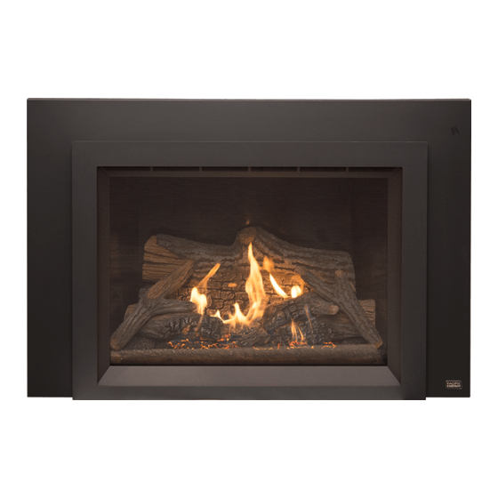
TOFINO
INSTALLATION
INSTRUCTIONS
MODEL: TOFINO i40s
TOFINO i40m
(SIT & Maxitrol G6R versions)
SERIES: A
DIRECT VENT GAS INSERT
TOFINO
100000300
Advertisement
Table of Contents

Related Manuals for Pacific energy Tofino Series


Summary of Contents for Pacific energy Tofino Series
- Page 1 INSTALLATION INSTRUCTIONS INSTALLER: Leave this manual with the appliance. CONSUMER: Retain this manual for future reference. WARNING: If the information in these instructions is not followed exactly a fire or explosion may result causing property damage, personal injury or death. TOFINO FOR YOUR SAFETY Do not store or use gasoline or other flammable...
-
Page 2: Table Of Contents
Table Of Contents Gas Valve for SIT Configuration ..........20 Important Note for the Commonwealth of Massachusetts: ..3 SIT controller ..............20 Caution ..................4 SIT gas valve ..............20 Safety ..................5 Gas valve for Maxitrol Configuration ........21 WHAT TO DO IF YOU SMELL GAS ........ -
Page 3: Important Note For The Commonwealth Of Massachusetts
Important Note for the Commonwealth of Massachusetts: From Massachusetts Rules and Regulations 248 5.08: For all side wall horizontally vented gas fueled equipment installed in every dwelling, building or structure used in whole or in part for residential purposes, including those owned or operated by the Commonwealth and where the side wall exhaust vent termination is less than seven (7) feet above finished grade in the area of the venting, including but not limited to decks and porches, the following requirements shall be satisfied. -
Page 4: Caution
Caution FOR YOUR SAFETY - Do not install or operate your Pacific Energy fireplace without first reading and understanding this manual. Any installation or operational deviation from the following instructions voids the Pacific Energy Fireplace Warranty and may prove hazardous. -
Page 5: Safety
Safety • Due to high temperatures, this gas appliance should be located out of traffic and away from furniture and draperies. • Children and adults should be alerted to the hazards of high surface temperatures and should stay away to avoid burns or clothing ignition. •... -
Page 6: First Fire
First Fire When lit for the first time, the fireplace will emit a slight odour for a couple of hours. This is due to the curing of paints, sealants and lubricants used in the manufacturing process. This condition is temporary. Open doors and windows to ventilate area. Odour caused by the curing process may cause discomfort to some individuals. -
Page 7: Fireplace Dimensions
Fireplace Dimensions Figure 1: Tofino Dimensions. Tofino i40 SIT Tofino i40 Maxitrol 4” 4” 6” 6” 15 3/4” 15 3/4” 17 3/8” Use dimension “C” 36 1/8” 36 1/8” 22 7/8” 22 7/8” 18 1/4” 18 1/4” 24 1/8” 24 1/8” 27”... -
Page 8: Tofino Insert Backing Plate Dimensions
Tofino Insert Backing Plate Dimensions Tofino i40 HEIGHT / WIDTH REGULAR 28” 42” OVERSIZED 31” 44” Figure 2: Tofino Surround dimensions. i40 TOFINO 051119-48 100000300... -
Page 9: Existing Fireplace Preparation
Existing Fireplace Preparation Note: SIT controlled installations require that an electrical outlet be installed either into an existing fireplace cavity before the Tofino is installed, or alternatively, the power cord can access a pre-existing power outlet elsewhere in the room by way of knock-out openings located on either side of the backing plate. -
Page 10: Clearances To Combustibles
Clearances to Combustibles Mantel Clearances 35” Mantel Depth Mantel Depth 14” Hearth Clearance Mantel Clearance 0” Objects in front of Appliance 36” Hearth Clearance Under Appliance Figure 4: Mantel clearance. 0” Horizontal Clearances Horizontal clearance to adjacent sidewall combustibles. Refer to Figure 5 20”... -
Page 11: Adjustable Leveling Bolts
Adjustable Leveling Bolts Adjustable leveling bolts This fireplace comes with two leveling bolts used to adjust the angle of the front of the fireplace (Figure 6) relative to the wall in which it’s installed. The bolts are pre- Side to side levelling installed. -
Page 12: Venting
Venting Flue adapters The Tofino i40 uses 3” flex tubing for the air intake and 4” flex tubing for the air exhaust. The Tofino i40 ships with a flue adapter which fits onto the top of the firebox and is affixed with a connection bolt (Figure 11). Depending on the amount of room available for the installation of the Tofino, the installer may want to remove the flue adapter and attach it to the flex tubes which will have previously been inserted down the chimney. - Page 13 Only certified venting systems or components may be installed with this fireplace. Max Vent Height Only the following vent terminals should be used for the Tofino i40. 40’ (12.2m) Min. Vent Height 10’ (3m) Manufacturer Model Model # Venting length Duravent High wind DVA-CL33 10’...
-
Page 14: Sit Control Overview
SIT Control Overview Figure 15: Proflame - SIT remote control device. Figure 14: SIT Proflame controller module. The SIT Proflame controller (Figure 14) is used along with the SIT Proflame gas valve (See “Figure 38” on page 20) . The use of the SIT Proflame controller requires a remote control device (provided) unique to the SIT Proflame configuration. -
Page 15: Door Installation/Removal
Door Installation/Removal Figure 18: Glass door and hooks. Figure 19: Unlocking the glass door. Approx. 3/4” Figure 21: Locking the glass door. Figure 20: Door handles in closed position. Removal 1. Remove the surround and backing plate from the front of the fireplace, “Surround Installation/Removal Instructions”... -
Page 16: Panel Installation
Panel Installation The panel sets are delicate and should be handled with care. The baffle and panel support bracket (Figure 22) retains the side panels, supports the front end of the ceramic glass baffle, and has a shield which directs the light from the ceiling of the firebox (available on i40s models only) down onto the log set (model dependent). - Page 17 Figure 25: Rear panel in place. Figure 26: Upper firebox corner and gasket. 2. Gently place the base of either of the two side panels along the edge of the firebox floor and wall. Then slowly tilt the top part of the panels up into the edge of the wall and ceiling. Be careful that the top corner of the panel closest to the front of the fireplace makes as little contact with the opening edge of the firebox and gasket (Figure 26) as possible as this may damage the panel.
-
Page 18: Baffle
Baffle Ceramic glass baf e Front baf e support Rear ceramic glass baf e & rear panel support posts Figure 29: Ceramic glass baffle. Figure 30: Inserting baffle into the upper corner. The baffle is made of ceramic glass which allows for the use of a halogen lamp feature. The halogen lamp is only available on units using the SIT Proflame configuration, the Maxitrol configuration does not include the use of a halogen lamp. -
Page 19: Electrical Supply
Electrical Supply Knock-out for power cord Figure 33: Electrical connection. Figure 34: Knock-out for power cord. Note: SIT controlled installations require that an electrical outlet be installed either into an existing fireplace cavity before the Tofino is installed, or alternatively, the power cord can access a pre-existing power outlet elsewhere in the room by way of knock-out openings located on either side of the backing plate (Figure 34). -
Page 20: Gas Valve For Sit Configuration
Gas Valve for SIT Configuration Figure 37: SIT control center. Figure 38: SIT Gas valve. SIT controller SIT gas valve The SIT controller is mounted The SIT gas valve assembly is onto a caddy which is located on mounted onto a caddy which is the left hand side of the fireplace located on the right hand side for easy access. -
Page 21: Gas Valve For Maxitrol Configuration
Gas valve for Maxitrol Configuration Maxitrol controller The Maxitrol controller is mounted onto a caddy which is located on the left hand side of the fireplace for easy access. Remove the surround to gain access to the controller. Figure 39: Maxitrol electrical controller in its caddy. Maxitrol gas valve The Maxitrol gas valve assembly is mounted onto a caddy which... -
Page 22: Gas Pressure Check / Output / Efficiency
Gas Pressure Check / Output / Efficiency Please refer to following page for gas pressure testing procedure. SIT Valve Maxitrol Valve Gas pressure requirements Gas pressure requirements Input Pressure Natural Gas Propane Input Pressure Natural Gas Propane Minimum 5.0” WC 12.5”... -
Page 23: Gas Pressure Testing Procedure
Gas Pressure Testing Procedure Note: This section covers gas pressure testing for both SIT and Maxitrol gas valves. Note: To test the gas pressure, turn off the gas supply to the appliance before loosening test point screws. Verify gas pressures with the fireplace lit and at the highest setting. 1. -
Page 24: Damper Adjustment
Damper Adjustment Closed Open Figure 45: Damper adjustment. Note: Be aware that the damper adjustment mechanism may be hot if the fireplace has been burning for any length of time. Tofino fireplaces come with an adjustable vent damper. This damper is located behind the air deflector at the rear of the inner firebox. -
Page 25: Venturi Adjustment
Venturi Adjustment Venturi closed Opened Closed Figure 47: Tofino venturi adjustments. Figure 48: Venturi closed. The Tofino has two burners and therefore, two venturis. The venturis are easily accessible and adjustable without having to remove the door. Venturi opened To adjust the venturis: 1. -
Page 26: Glass Media Installation
Glass Media Installation 1. With the interior panels and the ceramic glass baffle installed, place the burner tray (Figure 50) inside and over the burners and secure in place (total of 10 screws to be used). Place the decorative front edge plate (Figure 51) so that it hooks over the edge of the burner tray. -
Page 27: Split Log Set Installation
Split Log Set Installation Left side Right side base piece base piece Center base piece Figure 54: Log set base pieces. Figure 56: Log number 2. Figure 55: Log number 1. Figure 58: Log number 4. Figure 57: Log number 3. Figure 59: Log number 5. -
Page 28: Log Set Installation
Log set Installation Note: Panel set must be installed before the Split log set installation begins. 1. Begin by placing the air deflector / 1st log support (Figure 64) behind the rear burner and up against the rear wall (Figure 65). Position so that the lip faces toward the front of the fireplace. Fasten the deflector down with supplied screws. - Page 29 Figure 67: Side mesh guard. Figure 68: Right side mesh guard in place. 3. Place the front mesh guard (Figure 69) along the front edge of the front burner. Secure with supplied screws. Fit the guards gap around the pilot assembly (Figure 70). Figure 69: Front mesh guard.
- Page 30 Figure 71: Front base piece. Figure 72: Installing left side base piece. 4. Install the front base piece (Figure 54) as shown in Figure 71. Make sure that indent on the bottom inside edge fits over the pilot assembly. 5. Install the left side base piece (Figure 54) as shown in Figure 72. 6.
- Page 31 Support spacer over left-hand side post Figure 75: Support spacer over post. Figure 76: 1st log placement. Rear wall Figure 77: Log one position on air Figure 78: Ember pieces spread on top of burner trays. deflector - 1st log support. 7.
- Page 32 Place extra ember pieces here to hide gaps Pilot location Air gaps Figure 79: Front tray filled lightly with ember pieces and Figure 80: Air gaps. pilot location. 10. Place log number two (Figure 56) so that the post protruding from the bottom of this log can be inserted into the hole of the left base piece.
- Page 33 Figure 83: 4th log placement. Figure 84: 5th log placement. 13. Place the 5th log (Figure 59) so that the bottom end of the log rests against the right wall panel and on top of the front base piece. Position the upper end so that the longer branch is cradled in the crook of the 4th log (Figure 84).
- Page 34 Spread out ember wool in this area Figure 87: Completed log set with ember wool. 17. Gently pull apart the individual pieces of the ember wool (Figure 63) so that they are not compressed or compacted and spread them in front of the logs to finish (Figure 87). i40 TOFINO 051119-48 100000300...
-
Page 35: Manual Switch Installation For Sit Units
Manual Switch Installation for SIT Units The manual ON/OFF switch for the fireplace comes semi-installed (Figure 89). All that is needed is to install the switch itself to the surround backing plate. To install ON/OFF Switch 1. Check that the ON/OFF Switch cable is plugged into the SIT module (jack X8) as shown in Figure 88. Note regarding batteries for the SIT module (Figure 88): Installation of batteries for the SIT module are not necessary if the fireplace is connected to AC power. - Page 36 2. With the surround backing plate positioned in front of the fireplace, position the switch in behind the open slot in the backing plate and screw into place (Figure 90). Note: The SIT remote handset and receiver can be paired at this time before the surround backing plate and surround are installed in their final locations.
-
Page 37: Manual Switch Installation For Maxitrol Units
Manual Switch Installation for Maxitrol Units The manual ON/OFF switch for the fireplace comes semi-installed. All that is needed is to install the switch itself to the surround backing plate. Figure 92: Switch connector at control module. Figure 91: Pre-installed ON OFF switch assembly. - Page 38 3. Use a 2mm Allen key to fasten the switch to the backing plate (Figure 94). ON / OFF Flame UP/Down Figure 94: Attaching switch to backing plate. 4. Install the surround backing plate and surround (Figure 95). Figure 95: On Off switch location for Maxitrol units. i40 TOFINO 051119-48 100000300...
-
Page 39: Pairing The Sit Remote Handset And Receiver
Pairing the SIT Remote Handset and Receiver 1. Install 4 AA batteries into the battery holder located behind the electronic control module on the pull - out caddy (Figure 96). Note: Batteries are not required if the fireplace is connected to an AC power source. 2. -
Page 40: Pairing The Maxitrol Remote Handset And Receiver
Pairing the Maxitrol Remote Handset and Receiver 1. Insert batteries four double “AA” batteries into the receiver module (Figure 99). 2. Install 3 AAA batteries into the Maxitrol remote handset (Figure 100). 3. The receiver must learn the handset code: Remove the decorative front followed by the backing plate (Figure 102 and Figure 103). -
Page 41: Surround Installation/Removal Instructions
Surround Installation/Removal Instructions Figure 102: Decorative front. Figure 103: Backing plate. The surround (Figure 102) attaches to the unit once the backing plate (Figure 103) has been installed. The surround easily fits into place by connecting all four of its hooks. Installation 1. -
Page 42: Lighting Instructions
Lighting Instructions Due to high surface temperatures, keep children, clothing and furniture away. Keep burner and FOR YOUR SAFETY READ BEFORE LIGHTING control compartment clean. See installation and operating instructions accompanying the appliance. WARNING: - Immediately call your gas supplier from a neighbour's phone. Follow If you do not follow these instructions exactly, a the gas supplier's instructions. -
Page 43: Maintenance
Replacement door can be obtained from your nearest Pacific Energy Fireplaces dealer. The size required is dependent on which version of Tofino is installed. Use original Tofino door only. -
Page 44: Wiring Diagram For Sit Proflame
Wiring Diagram for SIT Proflame Caution: Label all wires prior to disconnection when servicing controls. Wiring errors can cause improper and dangerous operation. Verify proper operation after servicing. LAMP COMFORT Figure 109: SIT wiring diagram. i40 TOFINO 051119-48 100000300... -
Page 45: Wiring Diagram For Maxitrol
Wiring Diagram for Maxitrol Main Burner 8 Wire Cable Pilot Burner Combination Interrupter Block Control Thermocurrent Cable SW Thermocurrent Cable TC Ignition Cable Receiver ON/OFF Flame UP/DOWN Antenna RESET Button Figure 110: Maxitrol wiring diagram. i40 TOFINO 100000300 051119-48... -
Page 46: Tofino I40 Rating Labels
Tofino i40 Rating Labels SIT Version WARNING: Improper installation, adjustment, alteration, service or maintenance can cause injury or property damage. This appliance equipped for altitudes 0 - 4500 ft. (0 - 1372 m) / Cet unité est conçu pour des altitudes variant entre Refer to the owner’s information manual provided with this appliance. -
Page 47: Rating Label Location
Rating label location The rating label for the Tofino is located on the left-hand outside wall of the insert. Figure 111: Rating label location. i40 TOFINO 100000300 051119-48... - Page 48 © 2019 Copyright Pacific Energy Fireplace Products LTD. Reproduction, adaptation, or translation without prior written permission is prohibited except as allowed under the copyright laws. For technical support, please contact your retailer Web site: www.pacificenergy.net 2975 Allenby Rd., Duncan, BC V9L 6V8...
Need help?
Do you have a question about the Tofino Series and is the answer not in the manual?
Questions and answers