Table of Contents
Advertisement
Quick Links
INSTALLER:
Leave this manual with the appliance.
CONSUMER:
Retain this manual for future reference.
WARNING: If the information in these
instructions is not followed exactly a fire
or explosion may result causing property
damage, personal injury or death.
FOR YOUR SAFETY
Do not store or use gasoline or other flammable
vapours and liquids in the vicinity of this or any
other appliance.
WHAT TO DO IF YOU SMELL GAS
• Do not try to light any appliance.
• Do not touch any electrical Switch.
• Do not use any phone in your building.
• Immediately call your gas supplier from a
neighbour's phone. Follow the gas supplier's
instructions.
• If you cannot reach your gas supplier call the
fire department.
Installation and service must be performed by
a qualified installer, service agency or the gas
supplier.
This appliance may be installed in an aftermarket
permanently located, manufactured home (USA
only) or mobile home, where not prohibited by
local codes.
This appliance is only for use with the type of
gas indicated on the rating plate. This appliance
is not convertible for use with other gases
unless a certified kit is used.
This appliance is suitable for installation in a
bedroom or bed sitting room.
Visit www.pacificenergy.net for the most recent version of this manual
150317-32
OPERATING INSTRUCTIONS
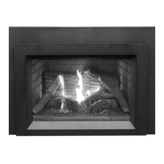
TOFINO
TOFINO OPERATING
INSTRUCTIONS
MODEL: TOFINO i20
(SIT & Maxitrol versions)
SERIES: A
DIRECT VENT GAS INSERT
5055.980-A
Advertisement
Table of Contents

Subscribe to Our Youtube Channel
Related Manuals for Pacific energy TOFINO i20


Summary of Contents for Pacific energy TOFINO i20
- Page 1 This appliance is not convertible for use with other gases unless a certified kit is used. MODEL: TOFINO i20 This appliance is suitable for installation in a (SIT & Maxitrol versions) bedroom or bed sitting room.
-
Page 2: Table Of Contents
Table Of Contents Caution ..................3 Setting the Time ............... 15 Safety ..................4 Child Proof ............... 15 WHAT TO DO IF YOU SMELL GAS ........4 Manual mode (handset) ........... 15 First Fire ..................5 Handset One-Button Operation ........16 Warnings and Cautions ............. -
Page 3: Caution
Caution FOR YOUR SAFETY - Do not install or operate your Paci c Energy replace without rst reading and understanding this manual. Any installation or operational deviation from the following instruc- tions voids the Paci c Energy Fireplace Warranty and may prove hazardous. This appliance and its individual shut off valve must be disconnected from gas supply piping system during any pressure testing of that system at test pressures in excess of 1/2 psig (3.5 kPa). -
Page 4: Safety
Safety • Due to high temperatures, this gas appliance should be located out of traf c and away from furniture and draperies. • Children and adults should be alerted to the hazards of high surface temperatures and should stay away to avoid burns or clothing ignition. • Young children should be carefully supervised when they are in the same room as the appliance. -
Page 5: First Fire
Congratulations on your purchase of a Pacifi c Energy Gas Appliance. Your replace has been professionally installed by: Dealer name: ___________________________________________________ Phone Number:___________________________________________________ If you discover any problems with your gas appliance contact your dealer immediately to have the unit repaired. Caution: Do not attempt to repair the replace because you may cause injury to yourself or others, and risk causing damage to the unit. -
Page 6: Remote Control Operation (Sit Pro Ame)
Remote Control Operation (SIT Profl ame) System Description The Pro ame 2 Remote Control System consists of two elements: 1. Pro ame 2 Remote Control Transmitter. 2. Pro ame Integrated Fireplace Control (IFC) (Figure 3) board and a wiring harness to connect the IFC to the gas valve and stepper motor. -
Page 7: Ifc Module
IFC Module The Pro ame 2 Integrated Fireplace Control (IFC) module (Figure 3) is a device that allows automatic ignition and pilot ame supervision, and commands the functions of the hearth Heater. It’s con gured to control the ON/OFF main burner operation, giving the choice of both IPI (intermittent pilot ignition), and CPI (continuous pilot ignition) modes. - Page 8 Figure 4: Program button. Figure 3: SIT electronic controller (IFC) mounted onto caddy. REMOTE Figure 5: On Off switch for SIT units. 150317-32 i20 TOFINO 5055.980-A...
-
Page 9: Temperature Indication Display
Temperature indication Display With the system in the “OFF” position, press the Thermostat Key and the Mode Key at the same time. Look at the LCD screen on the transmitter to verify that a C or F is visible to the right of the Room Temperature display (Figure 6 and Figure 7). -
Page 10: Remote Flame Control
Remote Flame Control The Pro ame has six (6) ame levels. With the system on, and the ame level at the maximum in the appliance, pressing the down arrow key once will reduce the ame height by one step until the ame is turned off. -
Page 11: Smart Thermostat (Transmitter Operation)
Smart Thermostat (Transmitter Operation) The Smart Thermostat function adjusts the ame height in accordance to the difference between the set point and the room temperatures. As the room temperature gets closer to the set point, the Smart Function will modulate the ame down. If the room temperature is cool, the Smart Function will modulate the ame up. To activate this function, press the THERMOSTAT key (Figure 1) until the word “SMART”... -
Page 12: Low Battery Power Detection
Continuous Pilot/Intermittent Pilot (CPI/IPI) selection With the system in the “OFF” position, press the Mode Key (Figure 1) to index to the CPI mode icon (Figure 18). Pressing the Up Arrow Key will activate the Continuous Pilot Ignition mode (CPI). Pressing the Down Arrow Key will return to IPI. -
Page 13: Remote Control Operation (Maxitrol)
Remote Control Operation (Maxitrol) Child Proof Time Signal Indicator Thermostatic Mode Battery Status Countdown Timer Fahrenheit or Celsius Program Mode Temperature Figure 20: Maxitrol 6 symbol display. Operating Instructions General Notes: Notice: Wiring of valve and receiver must be completed before starting ignition. Failure to do so could damage the electronics. -
Page 14: Setting The Electronic Code
WARNING • Battery replacement is recommended at the beginning of each heating season. • Old or dead batteries should be removed immediately. If left in the unit the batteries can overheat, leak, and / or explode. • Do NOT expose batteries (including during storage) to direct sunlight, excessive heat, re, mois- ture, or severe impact. -
Page 15: Setting Fahrenheit Or Celsius
Setting Fahrenheit or Celsius To change between °C and °F, press buttons simultaneously. NOTE: Choosing °F results in a 12 hour clock. Choosing °C results in a 24 hour clock. Figure 21: Setting F or C. Setting the Time 1. Press buttons simultaneously. -
Page 16: Handset One-Button Operation
Handset One-Button Operation (Default Setting) • Press until two short beeps and a blinking series of lines con rms the start sequence has begun; release button. • Main gas ows once pilot ignition is con rmed. • Handset automatically goes into Manual Mode after main burner ignition. NOTICE Change from one-button to two-button ignition operation by pressing and holding button for 10 seconds immediately after installing batteries. -
Page 17: Flame Height Adjustment
Flame Height Adjustment Handset • To increase ame height, press and hold button. • To decrease ame height or to set appliance to pilot ame, press and hold button. Figure 27: Flame height adjustment. Designated Low Fire and High Fire NOTE: Back-light must be on for high re and low re double - click operation. -
Page 18: Countdown Timer
Countdown Timer ON/SETTING: 1. Press and hold button until displayed and hour ashes. 2. To select hour, press button. button. Minutes ash. 3. To con rm, press 4. To select minutes, press button. 5. To con rm, press or wait. OFF: Press button, and countdown time disappears. -
Page 19: Thermostatic Mode
Thermostatic Mode Press . displayed, preset temperature displayed brie y, and then room temperature displayed. OFF: 1. Press button. 2. Press button to enter Manual Mode. 3. Press button to enter Program mode. Figure 33: Thermostatic mode. SETTING: 1. Press button and hold until displayed, temperature ashes. - Page 20 TEMPERATURE SETTING: 1. Press button and hold until ashes ON and set temperature (setting in Thermostatic Mode) displayed. 2. To continue, press button or wait. , OFF displayed, temperature ashes. 3. Select off temperature by pressing button. 4. To con rm, press button.
-
Page 21: To Turn On Appliance
NOTE: Either continue to PROGRAM 2 and set on and off times or stop programming at this point, and PROGRAM 2 remains deactivated. NOTE: PROGRAM 1 and 2 use the same on (Thermostatic) and off temperatures for and Daily Timer ). - Page 22 (A) Increase ame height (B) ON / OFF (C) Decrease ame height Figure 41: Touch pad - Backing plate switch. ON / OFF Flame UP/Down Figure 42: On Off switch location for Maxitrol units. 150317-32 i20 TOFINO 5055.980-A...
- Page 23 To turn on appliance • Press “B” button (See Figure 41 and Figure 42) until two short beeps con rm the start sequence has begun; release button. • Once pilot ignition is con rmed, there is main gas ow. WARNING If the pilot does not stay lit after several tries, turn the main valve knob to OFF and follow the instructions “To Turn Off Gas Appliance.”...
-
Page 24: To Turn Off Gas Appliance
To Turn Off Gas Appliance. 1. Place ON/OFF switch (if equipped) in O (OFF) position. 2. If gas control is accessible, turn main valve knob to the OFF full clockwise position. Automatic Turn Down 3 Hour No Communication Function • The valve will turn to pilot ame if there is no communication between handset and receiver for a 3 hour period. -
Page 25: Receiver
Receiver NOTICE 1. Insert batteries four double “AA” batteries into the receiver module. 2. The receiver has to learn the handset code: Remove the front surround (Figure 47 on page 28) followed by the backing plate (Figure 48 on page 28). Locate the caddy on the left-hand side of the replace. The reset button is located here. -
Page 26: Lighting Instructions
Lighting Instructions Due to high surface temperatures, keep children, clothing and furniture away. Keep burner and FOR YOUR SAFETY READ BEFORE LIGHTING control compartment clean. See installation and operating instructions accompanying the appliance. WARNING: - Immediately call your gas supplier from a neighbour's phone. Follow If you do not follow these instructions exactly, a the gas supplier's instructions. -
Page 27: Maintenance
Maintenance CAUTION: PILOT Turn off gas and electrical power supply (if applicable) and allow ample time for unit to cool before servicing appliance. It is recommended that the replace and its venting should be inspected at least once a year by a quali ed service person. FLAME SENSOR PILOT FLAME Glass Door:... -
Page 28: Surround Installation/Removal Instructions
Surround Installation/Removal Instructions Figure 47: Surround. Figure 48: Backing plate. The surround (Figure 47) attaches to the unit once the surround backing plate (Figure 48) has been installed. The surround easily ts into place by connecting all four of its hooks. Removal 1. -
Page 29: Door Installation/Removal
Door Installation/Removal Figure 51: Glass door and hooks. Figure 52: Unlocking the glass door. Approx. 3/4” (20mm) gap Figure 54: Locking the glass door. Figure 53: Door handles in closed position. Removal 1. Remove the surround and backing plate from the front of the replace, “Surround Installation/Removal Instructions”... - Page 30 150317-32 i20 TOFINO 5055.980-A...
- Page 31 i20 TOFINO 150317-32 5055.980-A...
- Page 32 © 2017 Copyright Paci c Energy Fireplace Products LTD. Reproduction, adaptation, or translation without prior written permission is prohibited except as allowed under the copyright laws. For technical support, please contact your retailer Web site: www. pacificenergy.net 2975 Allenby Rd., Duncan, BC V9L 6V8...
Need help?
Do you have a question about the TOFINO i20 and is the answer not in the manual?
Questions and answers