Pacific energy PACIFIC FP30 Installation And Operating Instructions Manual
Hide thumbs
Also See for PACIFIC FP30:
- Installation and operating instructions manual (32 pages) ,
- Installation and operating instructions manual (28 pages) ,
- Installation and operating instructions manual (28 pages)
Table of Contents
Advertisement
Quick Links
IMPORTANT:
THESE INSTRUCTIONS ARE TO
REMAIN WITH THE HOMEOWNER.
PLEASE SAVE THESE INSTRUCTIONS.
SAFETY NOTICE
If this stove is not properly installed, a
house fi re may result. For your safety,
follow the installation instructions. Contact
local building or fire officials about
restrictions and installation inspection
requirements in your area.
TESTED and LISTED to CAN/ULC
S610-M87 AND UL 127
Meets the Environmental Protection
Agency's July 1990 Particulate Emission
Standards
190712-28
INSTALLATION
AND OPERATING
INSTRUCTIONS
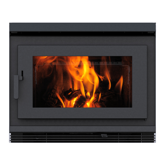
MODEL: PACIFIC FP30
ZERO CLEARANCE WOOD
FIREPLACE
PACIFIC FP30
SERIAL #
5055.5152
Advertisement
Table of Contents

Subscribe to Our Youtube Channel
Related Manuals for Pacific energy PACIFIC FP30


Summary of Contents for Pacific energy PACIFIC FP30
-
Page 1: Safety Notice
TESTED and LISTED to CAN/ULC S610-M87 AND UL 127 Meets the Environmental Protection Agency's July 1990 Particulate Emission Standards MODEL: PACIFIC FP30 ZERO CLEARANCE WOOD FIREPLACE 190712-28 PACIFIC FP30 5055.5152... -
Page 2: Table Of Contents
Troubleshooting ................... 23 heater. Failure to follow instructions Understanding & Operating Your Pacifi c Energy Stove ......24 may result in property damage, bodily Replacement Parts ................25 injury, or even death. Label Location ..................27 Label ....................27 PACIFIC FP30 190712-28... -
Page 3: Safety And Maintenance
Periodically inspect seals and replace if necessary. 7. DOOR GLASS - Replacement glass can be obtained from your dealer. Use 11 3/8" x 21 5/8" x 5 mm. WARNING: DO NOT SUBSTITUTE GLASS WITH ANY OTHER TYPE MATERIAL OTHER THAN CERAMIC GLASS PACIFIC FP30 190712-28... -
Page 4: Creosote
In the event of a Chimney Fire 1. Prepare to evacuate to ensure everyone's safety. Have a well understood plan of action for evacuation. Have a place outside where everyone is to meet. 2. Close air inlet on stove. PACIFIC FP30 190712-28... -
Page 5: Operation
3. Use wood of different shape, diameter and length (up to Your PACIFIC ENERGY heater is designed for maximum 20"). Load your wood endwise and try to place the logs overall efficiency at a moderate fi ring rate. Over fi ring is so that the air can fl ow between them. -
Page 6: More Wood, More Heat
It is also recommended that the blower be wired to a wall switch or dimmer switch for manual control. If the blower should ever need to be replaced, power to the blower can be shut off at the switch during replacement. PACIFIC FP30 190712-28... -
Page 7: Blower Replacement
3" FLEX TUBE FIG. #1 FIG. #4 BOLTS WINGNUTS FIG. #5 Electrical Rating : 115 V, 60 Hz, 1.1A NUTS Thermo Blower Switch TERMINAL BLOCK MALE/FEMALE 110VAC SWITCHED CONNECTION 110VAC COMMON GROUND USE ONLY COPPER CONDUCTORS 120412 5050.7434 PACIFIC FP30 190712-28... -
Page 8: Firebrick Installation
(230 mm x 115 mm x 32 mm) 5096.99 9” X 3 1/2” X 1 1/4” (102 mm x 115 mm x 32 mm) 3245.501 7 1/4” X 4 1/2” X 1 1/4” (184 mm x 115 mm x 32 mm) 245.001 PACIFIC FP30 190712-28... -
Page 9: Crate Removal
Ideally, you should choose a location where the chimney will pass through the house without cutting fl oor or roof joists. FIG. #6 RECOMMENDED LOCATIONS THIS LOCATION THIS LOCATION NOT RECOMMENDED OUTSIDE AIR INTAKE PACIFIC FP30 190712-28... -
Page 10: Dimensions
12. Anchor the Framing kit to the wood framing on the sides and top. Dimensions FIG. #8 29 1/2" FP30 25" 30 3/4" 45" 28 1/8" 21 7/8" 11 1/4" 44" PACIFIC FP30 190712-28... -
Page 11: Minimum Framing Dimensions
Minimum Framing Dimensions 60" FIG. #10 NOTE: THE FRAMING DIMENSIONS AROUND 1" THE FIREPLACE MUST INCLUDE THE INNER DRYWALL BOARD. 10" 26" " " " " " " " " " " PACIFIC FP30 190712-28... -
Page 12: Framing Kit Assembly
Using the screws provided (1), attach the framing kit legs(4) to the bottom stud (2). • Next, attach each center support(3) to the bottom stud(2) and then attach the top stud(2) to the center supports(3). FIG. #9 PACIFIC FP30 190712-28... -
Page 13: Minimum Clearances To Combustibles
Minimum Clearances to Combustibles 1" 30" FIG. #11 6 3/8" 10" 27 3/8" 9" 6 3/8" PACIFIC FP30 190712-28... - Page 14 A 4" outside air inlet is also on the left side of the unit for outside fan air. The combustion air inlets can be rotated to draw air from the rear of the unit if desired. PACIFIC FP30 190712-28...
-
Page 15: Chimney Installation
1" Solid Pack. 6" (152mm) USA ONLY: Security Secure Temp ASHT 1" Solid Pack 6" (152mm) Selkirk Ultra-Temp 1" Solid Pack 6" (152mm) Excel 1" Solid Pack. 6" (152mm) Simpson Dura-Vent DuraTech Class-A 1" Solid Pack. 6" (152mm) PACIFIC FP30 190712-28... -
Page 16: Offsets
Maximum chimney height supported by fireplace. 25’ (7.62m) Minimum depth of non-combustible hearth extension: from the front of the 18” (457mm) fireplace. Minimum width of floor protection from side of door opening(in U.S.A.) and from side of unit(in Canada). PACIFIC FP30 190712-28... -
Page 17: Combustion Air
If blockage occurs, fl ue gases may enter living space. A typical outside air connection is shown in Fig. #15. PACIFIC FP30 190712-28... -
Page 18: Safety Strip
Electrical Rating : 115 V, 60 Hz, 1.1A Minimum Overall Depth - 19 1/8" Thermo Blower Switch TERMINAL BLOCK MALE/FEMALE 110VAC SWITCHED CONNECTION 110VAC COMMON GROUND 19 1/8" 8" [203mm] 8" [203mm] [486mm] 120412 5050.7434 18" [457mm] Non-combustible fl oor protector PACIFIC FP30 190712-28... -
Page 19: Remote Heat Duct Installation
1. Using a pair of tin snips, cut away the square section block- ing the heat duct openings and cut out insulation(Fig.#20). 2. Attach the heat duct adapter/s with the screws provided in the FP30.GVKIT (Fig. #20). PACIFIC FP30 190712-28... - Page 20 1/2” thick(Max. 4"), connect additional room TABS air to the 6" Gravity Vent air inlet on the left side of the fi replace casing using the adapter provided(Fig. #23). FIG. #21 11 1/4” FIG. #23 9 3/4” WALL OUTLET PACIFIC FP30 190712-28...
-
Page 21: Facing And Air Inlet
Tape and mud the joints as per the board manufacturers recommendations. 1 1/2” 1” 1” 3/4” FACING FLANGES FIG. #25 NON-COMBUSTIBLE CEMENT BOARD 36.00 REQUIRED DECORATIVE NON-COMBUSTIBLE FACING MAXIMUM 4” THICK 30in2 (194cm2) CHASE AIR INLET 1 1/2” 60.00 ALTERNATE LOCATION FOR CHASE AIR INLET PACIFIC FP30 190712-28... -
Page 22: Mantel Clearances
ELECTRICAL WIRING OR GAS PLUMBING IN THIS AREA. MANTEL CLEARANCE CHART MANTEL CLEARANCE A-CANADA 42”(NO GRAVITY VENT) NON-COMBUSTIBLE 16 1/2” FACING MATERIAL A-CANADA 34"(GRAVITY VENT) COVERING FROM THE CONVECTION AIR OUT- A-U.S.A. 34" LET TO THE CEILING. MANTEL DEPTH 2" TO 12" PACIFIC FP30 190712-28... -
Page 23: Troubleshooting
1. Combustion air supply blocked - Check outside air supply for obstruction - Check that room air cover is removed 2. Draft too low - Chimney plugged or restricted, inspect and clean - Chimney oversized or otherwise unsuitable, consult Dealer PACIFIC FP30 190712-28... -
Page 24: Understanding & Operating Your Pacifi C Energy Stove
1 -Boost Air 4 -Secondary Combustion Zone 2 -Main Combustion Air 5 -Radiant Heat 3 -Air Wash System 6 -Convected Heat PACIFIC FP30 190712-28... -
Page 25: Replacement Parts
*18 ..Access Cover Gasket ......5068.81016 *19 ..Gravity Vent Adapter ....... FP30.9128 All parts may be ordered from your nearest Pacifi c Energy NOT SHOWN dealer. Contact Pacifi c Energy for the location of the dealer nearest you. FP30.DRBK PACIFIC FP30 190712-28... - Page 26 PACIFIC FP30 190712-28...
-
Page 27: Label Location
• BLOWER ELECTRICAL RATING 115V, 60HZ, 1.0AMP • REPLACE GLASS ONLY WITH 5mm CERAMIC GLASS. • DO NOT USE OR INSTALL COMPONENTS OR PRODUCTS NOT SPECIFIED IN PACIFIC ENERGY INSTALLATION INSTRUCTIONS. DO NOT USE A FIREPLACE INSERT OR OTHER PRODUCTS NOT SPECIFIED FOR USE WITH THIS PRODUCT. - Page 28 PACIFIC ENERGY FIREPLACE PRODUCTS LTD. 2975 Allenby Rd., Duncan, B.C. V9L 6V8 Phone: 250-748-1184 Web site: http://www.pacifi cenergy.net Printed in Canada...
Need help?
Do you have a question about the PACIFIC FP30 and is the answer not in the manual?
Questions and answers