Table of Contents
Advertisement
IMPORTANT:
THESE INSTRUCTIONS ARE TO
REMAIN WITH THE HOMEOWNER
SAFETY NOTICE
If this stove is not properly installed, a house
fi re may result. For your safety, follow the
installation instructions.
building or fi re officials about restrictions
and installation inspection requirements in
you area.
TESTED and LISTED to CAN/ULC S627
and UL 1482
Meets the Environmental Protection
Agency's July 1990 Particulate
Emission Standards
210513-24
INSTALLATION
Contact local
AND OPERATING
INSTRUCTIONS
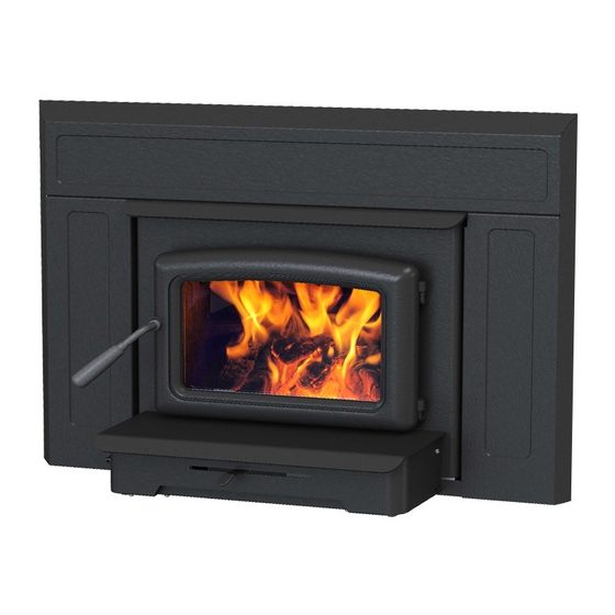
Model:
PACIFIC VISTA INSERT
Series: D
VISTA INSERT-D
SERIAL #
5055.3231
Advertisement
Table of Contents

Related Manuals for Pacific energy PACIFIC VISTA INSERT Series D


Summary of Contents for Pacific energy PACIFIC VISTA INSERT Series D
-
Page 1: Safety Notice
IMPORTANT: THESE INSTRUCTIONS ARE TO REMAIN WITH THE HOMEOWNER SERIAL # SAFETY NOTICE If this stove is not properly installed, a house fi re may result. For your safety, follow the INSTALLATION installation instructions. Contact local building or fi re officials about restrictions AND OPERATING and installation inspection requirements in INSTRUCTIONS... -
Page 2: Table Of Contents
Contents Safety .................... 3 Dimensions .................... 3 Clearances ................... 3 Masonry or Factory Built Fireplace ............3 Maintenance Checks ..............4 Installation ..................6 Fireplace Specifi cations ................. 6 Into a Masonry Fireplace ............... 6 Full Flue Liner -(Required in Canada) ............ 7 Direct Flue Connection - (USA only) ............. -
Page 3: Safety
Clearances Safety Masonry or Factory Built Fireplace READ ALL INSTRUCTIONS BEFORE INSTALLING AND USING THIS APPLIANCE. FAILURE TO FOLLOW The minimum required clearances to surrounding combustible INSTRUCTIONS MAY RESULT IN PROPERTY DAMAGE, materials when installed into a masonry or factory built fi replace BODILY INJURY, OR EVEN DEATH. -
Page 4: Maintenance Checks
Maintenance Checks Check the following parts for damage such as cracks, excessive corrosion, burned out sections and excessive warping: (See website for descriptions and more detail) Weekly: - Firebrick - Visual, for cracking. - Door Gasket - sagging, placement, damage. Monthly - Brick rail tabs and brick rails. - Page 5 Fireplace hearth requirements: (Measured without the insert) The hearth may be fl ush with or raised above an adjacent combustible fl oor and must extend 16” in front and 8” beyond each side of the fi replace opening. MINIMUM FIREPLACE OPENING AND HEARTH DIMENSIONS 16”...
-
Page 6: Installation
Installation Fig. # 4 Full Flue Liner Your Insert is designed to be installed into a masonry or fac- tory built zero-clearance fi replace. The masonry fi replace must be built according to the requirements of the Standard of Chimneys, Fireplaces, Vents and Solid Fuel Burning ap- Rain Cap pliances, N.F.P.A. -
Page 7: Full Flue Liner -(Required In Canada)
Full Flue Liner -(Required in Canada) Direct Flue Connection 1) Measure the chimney height from the top of the existing Fig. # 7 fl ue to the fl oor of the hearth. This will allow extra length of liner for fl ashing and rain cap. 2) Feed the stainless steel liner from top of the chimney, Mantel or Chimney... -
Page 8: Surround Assembly And Installation
Surround Assembly and Installation 1) Lay part A, B and C face down on a fl at non-marring surface. Fasten together with 1/4" x 1/2" bolts and nuts provided through holes at points “D” (Fig. #8 and 9). Fig. # 10 2) Lift the surround assembly to the upright position and make sure the front face is fl at and even at the joints. -
Page 9: Combustion Air
Combustion Air Blower Consult local building codes regarding combustion air supply. Intake or combustion air can be supplied to the Insert in one The Insert comes equipped with a variable speed circulating of two ways: air blower. The blower system is thermostatically controlled 1) Outside air supply: Remove cover from ash clean out in for automatic operation, as well manually with a convenient existing fi replace. -
Page 10: Operation
Your PACIFIC ENERGY heater is designed for many years of WARNING: No alteration or modifi cation of the combus- trouble free operation. Over fi ring the appliance will shorten tion air control assembly is permitted. -
Page 11: Proper Draft
Proper Draft In summary, a certain amount of creosote is inevitable and must be lived with. Regular inspection and cleaning is the solution. The use of dry, seasoned wood and ample combus- 1) Draft is the force which moves air from the appliance up tion air will help to minimize the buildup. -
Page 12: Maintenance
Maintenance Remove all particles of glass. Be careful as they are very sharp. Install new glass complete with gasket. Replace frame and screws. WARNING: Do not overtighten, tighten screws very 1. Burn wood only, dry and well seasoned. The denser or carefully. -
Page 13: Troubleshooting
Appendix A Troubleshooting Problem Cause Cure Excessive Creosote 1) Wood is too wet - Use dry wood Buildup 2) Turning down air control - Do not turn down until: too soon a) there is a good bed of coals b) the wood is charred 3) Draft too low - Improper chimney height and/or diameter - Chimney plugged or restricted, check fl ue... -
Page 14: Firebrick Installation Instructions
Firebrick Installation Instructions Pacifi c Vista Insert This package contains 12 full-size fi rebricks. With the heater in the upright position, install fi rebricks as follows: - First, install 4 fi rebricks against the rear wall. - Next, install the side fi rebricks, 2 each side. - Lastly, place 4 fi rebricks on the bottom of the heater. -
Page 15: Replacement Parts
Replacement Parts ITEM DESCRIPTION PART NO. ITEM DESCRIPTION PART NO. 1..Ash Lip/Blower Assembly ........VIND.BLOW 2..Air Control Cover ............... 2327 20..Casing Bottom ..............2321 3..Blower Bracket ..............2343 22..Surround, Regular ..........VIND.SRNDA 4..Glass Clamp Kit (c/w Screws) ........SSER.1425 23..Surround, Oversize (not shown) ..... VINC.SURROSC 5..Glass Bar Kit (2 pcs.) ...........DR16.212501 25..Casing Top, Front ............... -
Page 16: Replacement Parts - Blower
Replacement Parts - Blower ITEM DESCRIPTION PART NO. ITEM DESCRIPTION PART NO. 8..Rocker Switch Wire ........VINC.503221 1..Ash Lip/Blower Housing ......... VINC.2310 1a...Ashlip ................2369 9..Rocker Switch ............5071 2..Blower Only ............5024.54 10 ...Rheostat Knob ............5026 3..Blower Bottom Cover ......... 2341.003 11 ...Rheostat ..............5025 4..Snap Disc Switch Bracket ......... -
Page 17: Optional Hearth Trim Kit
Pacifi c VISTA INSERT Optional Hearth Trim Kit This kit contains: 1..Hearth Trim 4..Spring Clips Installation: Unpack and inspect the hear th trim. Install the surround assembly as per instruction supplied with the appliance. Attach hearth trim to the bottom of the surround with clips provided. - Page 18 VISTA INSERT-D 210513-24...
-
Page 19: Label
MODEL / MODÈLE: PACIFIC VISTA INSERT SERIES / SÉRIE: D INSTALL AND USE ONLY IN ACCORDANCE WITH PACIFIC ENERGY’S INSTALLATION AND OPERATING INSTRUCTIONS. CONTACT LOCAL BUILDING OR FIRE OFFICIALS ABOUT CODES, RESTRICTIONS AND INSTALLATION INSPECTION IN YOUR AREA. INSTALL AND USE ONLY IN MASONRY OR FACTORY BUILT FIREPLACE. DO NOT CONNECT THIS UNIT TO A CHIMNEY FLUE SERVING ANOTHER APPLIANCE. - Page 20 PACIFIC ENERGY FIREPLACE PRODUCTS LTD. PACIFIC ENERGY FIREPLACE PRODUCTS LTD. Phone: 1-250-748-1184 Phone: 1-250-748-1184 Web site: http://www.pacifi cenergy.net Web site: http://www.pacifi cenergy.net 2975 Allenby Rd., Duncan, B.C. V9L 6V8 2975 Allenby Rd., Duncan, B.C. V9L 6V8 Printed in Canada...
Need help?
Do you have a question about the PACIFIC VISTA INSERT Series D and is the answer not in the manual?
Questions and answers