Perkins 400 Series Operation And Maintenance Manual
Industrial engine
Hide thumbs
Also See for 400 Series:
- User handbook manual (76 pages) ,
- Operation and maintenance manual (100 pages) ,
- Operation and maintenance manual (88 pages)

Related Manuals for Perkins 400 Series


Summary of Contents for Perkins 400 Series
- Page 1 SEBU7992-01 November 2004 Operation and Maintenance Manual 400 Industrial Engine HB (Engine) H D (Engine) H H (Engine) HL (Engine) H N (Engine) HP (Engine) HR (Engine)
- Page 2 Obtain the complete and most current information before you s t ar t any jo b . Perkins dea le rs hav e t he m os t c ur r en t i nfo rm ati on a va il abl e.
-
Page 3: Table Of Contents
SEBU7992-01 Table of Contents Table of Contents Foreword ..............4 Safety Section General Hazard Information ........5 Burn Prevention ............6 Fire Prevention and Explosion Prevention ....6 Crushing Prevention and Cutting Prevention ..8 Before Starting Engine ..........9 Engine Starting ............ -
Page 4: Foreword
They assist with developing the skills and Perkins authorized personnel. Your Perkins dealer techniques required to operate the engine more or your Perkins distributor offers a variety of options efficiently and economically. Skill and techniques regarding overhaul programs. If you experience... -
Page 5: Safety Section
SEBU7992-01 Safety Section General Hazard Information Safety Section Obey all local regulations for the disposal of liquids. Use all cleaning solutions with care. Report all necessary repairs. i02203039 General Hazard Information Do not allow unauthorized personnel on the equipment. Note: Ensure that the power supply is disconnected before you work on the bus bar or the glow plugs. -
Page 6: Burn Prevention
SEBU7992-01 Safety Section Burn Prevention Coolant When the engine is at operating temperature, the engine coolant is hot. The coolant is also under pressure. The radiator and all lines to the heaters or to the engine contain hot coolant. Any contact with hot coolant or with steam can cause severe burns. - Page 7 Personal injury, property damage, or engine damage could result. If the application involves the presence of combustible gases, consult your Perkins dealer and/or your Perkins distributor for additional information about suitable protection devices. Remove all flammable combustible materials or conductive materials such as fuel, oil, and debris from the engine.
-
Page 8: Crushing Prevention And Cutting Prevention
Crushing Prevention and Cutting Prevention Repair any lines that are loose or damaged. Leaks can cause fires. Consult your Perkins dealer or your Perkins distributor for repair or for replacement parts. Check lines, tubes and hoses carefully. Do not use your bare hand to check for leaks. -
Page 9: Before Starting Engine
Do not bypass the automatic shutoff circuits. Do not disable the automatic shutoff circuits. The circuits are The 400 Series engines are equipped with a glow provided in order to help prevent personal injury. The plug starting aid in each individual cylinder that heats circuits are also provided in order to help prevent the intake air in order to improve starting. -
Page 10: Electrical System
SEBU7992-01 Safety Section Electrical System On the initial start-up of a new engine or an engine that has been serviced, make provisions to stop the engine if an overspeed condition occurs. This may be accomplished by shutting off the fuel supply and/or the air supply to the engine. -
Page 11: Product Information Section
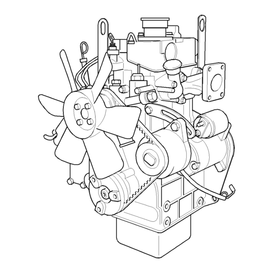
Model Views i02156530 Model View Illustrations The following model views show typical features of the 400 series engines. Due to individual applications, your engine may appear different from the illustrations. Note: Individual components are detailed on the 404C-22T turbocharged engine only. - Page 12 SEBU7992-01 Product Information Section Model Views g01109212 Illustration 8 Typical view of the 403C-11 engine...
- Page 13 SEBU7992-01 Product Information Section Model Views g01097209 Illustration 9 Front and left side view of the 404C-22T Engine (1) Engine oil filler cap (7) Exhaust manifold (13) Engine oil drain plug (2) Coolant temperature switch (8) Turbocharger (14) Engine oil pan (3) Crankcase breather (9) Starting motor solenoid (15) Crankshaft pulley...
- Page 14 The 400 series engines are diesel engines that are controlled with a mechanically actuated fuel injection The crankshaft for a two cylinder engine has two pump.
- Page 15 SEBU7992-01 Product Information Section Model Views Engine Specifications The timing gears are stamped with timing marks in order to ensure the correct assembly of the gears. When the No. 1 piston is at top center compression Note: The front end of the engine is opposite the stroke, the teeth that are stamped on the crankshaft flywheel end of the engine.
- Page 16 SEBU7992-01 Product Information Section Model Views 402C-05 Engine 403C-07 Engine g01108476 g00852304 Illustration 11 Illustration 12 (A) Exhaust valves (A) Exhaust valves (B) Inlet valves (B) Inlet valves Table 1 Table 2 402C-05 Engine Specifications 403C-07 Engine Specifications Maximum Operating Maximum Operating 3600 rpm 3600 rpm...
- Page 17 SEBU7992-01 Product Information Section Model Views 403C-11 Engine 403C-15 Engine g00852304 g00852304 Illustration 13 Illustration 14 (A) Exhaust valves (A) Exhaust valves (B) Inlet valves (B) Inlet valves Table 3 Table 4 403C-11 Engine Specifications 403C-15 Engine Specifications Maximum Operating Maximum Operating 3600 rpm 3000 rpm...
- Page 18 SEBU7992-01 Product Information Section Model Views 404C-15 Engine 404C-22 Engine g00296424 g00296424 Illustration 15 Illustration 16 (A) Exhaust valves (A) Exhaust valves (B) Inlet valves (B) Inlet valves Table 5 Table 6 404C-15 Engine Specifications 404C-22 Engine Specifications Maximum Operating Maximum Operating 3000 rpm 3000 rpm...
- Page 19 SEBU7992-01 Product Information Section Model Views 404C-22T Engine g00296424 Illustration 17 (A) Exhaust valves (B) Inlet valves Table 7 404C-22T Engine Specifications Maximum Operating 3000 rpm Speed (rpm) Cylinders and In-Line four cylinder Arrangement Bore 84.0 mm (3.31 inch) Stroke 100.0 mm (3.94 inch) Displacement 2.216 L (135.229 in...
-
Page 20: Product Identification Information
Reference Numbers Engine Identification Information for the following items may be needed to Perkins engines are identified by a serial number. order parts. Locate the information for your engine. This number is shown on a serial number plate that Record the information in the appropriate space. - Page 21 SEBU7992-01 Product Information Section Product Identification Information g01098670 Illustration 19...
-
Page 22: Operation Section
Engine Lifting fixtures obsolete. If alterations are made, ensure that correct lifting devices are provided. Consult your Perkins dealer or your Perkins distributor for information regarding fixtures for correct engine lifting. i02134814... - Page 23 Note: Certain corrosion inhibitors could cause damage to some engine components. Contact the Service Department of Perkins for advice. If freezing temperatures are expected, check the cooling system for adequate protection against 8. Operate the engine for a short period in order to freezing.
- Page 24 When the engine protection has been completed in accordance with these instructions, this ensures that no corrosion will occur. Perkins are not responsible for damage which may occur when an engine is in storage after a period in service.
-
Page 25: Gauges And Indicators
Determine and correct the cause of any significant change in the readings. Consult your Perkins dealer or your Perkins distributor for assistance. Ammeter – This gauge indicates the amount of charge or discharge in the battery charging circuit. -
Page 26: Features And Controls
SEBU7992-01 Operation Section Features and Controls Features and Controls i02224052 Fuel Shutoff The fuel shutoff solenoid is located on the governor or the fuel shutoff solenoid is located on the fuel injection pump. When the fuel shutoff solenoid is activated, the solenoid moves the fuel rack “OFF”. The fuel shutoff solenoid moves the fuel rack directly or the fuel shutoff solenoid moves the fuel rack through the governor. -
Page 27: Engine Starting
SEBU7992-01 Operation Section Engine Starting Engine Starting • Do not start the engine or move any of the controls if there is a “DO NOT OPERATE” warning tag or similar warning tag attached to the start switch or to the controls. i02194223 Before Starting Engine •... - Page 28 SEBU7992-01 Operation Section Engine Starting Refer to the OEM manual for your type of controls. i02177935 Use the following procedure to start the engine. Starting with Jump Start Cables 1. Move the throttle lever to the full throttle position before you start the engine. NOTICE Do not operate the glow plugs for more than 60 sec- onds at one time.
- Page 29 SEBU7992-01 Operation Section Engine Starting 3. Connect one negative end of the jump start cable to the negative cable terminal of the electrical source. Connect the other negative end of the jump start cable to the engine block or to the chassis ground.
-
Page 30: Engine Operation
Fu el Con servation P rac tices i02176671 Engine Operation The efficiency of the engine can affect the fuel economy. Perkins design and technology in manufacturing provides maximum fuel efficiency in all applications. Follow the recommended procedures Correct operation and maintenance are key factors... -
Page 31: Engine Stopping
SEBU7992-01 Operation Section Engine Stopping Engine Stopping i02176672 After Stopping Engine i01935195 Stopping the Engine Note: Before you check the engine oil, do not operate the engine for at least 10 minutes in order to allow the engine oil to return to the oil pan. NOTICE •... -
Page 32: Cold Weather Operation
These Viscosity of the Engine Lubrication factors and recommendations from your Perkins dealer or your Perkins distributor are based on past proven practices. The information that is contained in this section should be combined in order to provide Correct engine oil viscosity is essential. - Page 33 An effective block heater is typically a 1250/1500 W unit. Consult your In addition, the engine must be thoroughly warmed in Perkins dealer or your Perkins distributor for more order to keep other engine parts in better condition information.
- Page 34 Perkins prefer only Group 1 and Group 2 fuels for can result due to changes in temperature. use in 400 Series engines. Group 3 fuels include Low Temperature Fuels and Aviation Kerosene Fuels. Before troubleshooting for low power or for poor performance in the winter, check the type of fuel that Note: Group 3 fuels reduce the life of the engine.
- Page 35 SEBU7992-01 Operation Section Cold Weather Operation For more information on cold weather operation, refer i01903588 to the Operation and Maintenance Manual, “Cold Fuel Related Components in Weather Operation and Fuel Related Components in Cold Weather Cold Weather”. Fuel Tanks Condensation can form in partially filled fuel tanks. Top off the fuel tanks after you operate the engine.
-
Page 36: Maintenance Section
SEBU7992-01 Maintenance Section Refill Capacities Maintenance Section 403C-07 Engine Table 9 403C-07 Engine Refill Capacities Refill Capacities Compartment or System Minimum Maximum i02194324 2.35 L 3.05 L Crankcase Oil Sump Refill Capacities (2.5 qt) (3.2 qt) Total Lubrication System These values are the approximate capacities for the crankcase oil sump which includes the standard factory installed oil filters. - Page 37 SEBU7992-01 Maintenance Section Refill Capacities 404C-15 Engine 402C-05 Engine Table 12 Table 14 404C-15 Engine 402C-05 Engine Refill Capacities Refill Capacities Compartment or System Minimum Maximum Compartment or System Liters Quarts 4.1 L 6.5 L Engine Only Crankcase Oil Sump (4.3 qt) (6.9 qt) External System Per OEM...
- Page 38 Compartment or System Liters Quarts the American Petroleum Institute (API) is recognized by Perkins. For detailed information about this Engine Only system, see the latest edition of the “API publication External System Per OEM No. 1509”. Engine oils that bear the API symbol are authorized by API.
- Page 39 These oils will also provide superior piston deposit The classifications CD-2 and American Petroleum Institute CF-2 are for two-cycle diesel engines. Perkins does not sell control for engines with either two-piece steel pistons engines that utilize CD-2 and API CF-2 oils.
- Page 40 TBN. These deposits can lead to a loss for conditions that demand a premium oil. Your of control of the oil consumption and to the polishing Perkins dealer or your Perkins distributor has specific of the cylinder bore. guidelines for optimizing oil change intervals.
- Page 41 Re-refined base stock oils are acceptable for service life or rated performance. Fully formulated, use in Perkins engines if these oils meet the finished oils consist of base oils and of commercial performance requirements that are specified by additive packages.
- Page 42 Group 3 (aviation kerosene fuels) To get the correct power and performance from • the engine, use a fuel of the correct quality. The Other fuels recommended fuel specification for Perkins engines is shown below: Group 1 (preferred fuels): Specification • Cetane number 45 minimum “DERV to EN590”...
- Page 43 5% spindle oil must be added. The fuel injection pump will not be covered by a warranty, Table 23 even when additives are included. Perkins Specifications for Distillate Diesel Fuel “JP5 MIL T5624 (Avcat FSII, NATO F44” Specifications Requirements...
- Page 44 6 °C (10 °F) minimum Pour Point “D97” NOTICE below ambient Operating with fuels that do not meet the Perkins rec- temperature ommendations can cause the following effects: Start- 0.2% maximum “D3605” ing difficulty, poor combustion, deposits in the fuel in-...
- Page 45 The fuels that are listed in this Table may not meet the Many engine failures are related to the cooling requirements that are specified in the “Perkins Specifications system. The following problems are related to cooling for Distillate Diesel Fuel” Table. Consult the supplier for the...
- Page 46 • Reduction of heat transfer Coolant Recommendations • Leakage of the water pump seal The following two coolants are used in Perkins diesel • Plugging of radiators, coolers, and small passages engines: Preferred – Perkins Extended Life Coolant (ELC) Glycol Acceptable –...
- Page 47 Engines that operate in an ambient temperature Containers of several sizes are available. Consult above 43 °C (109.4 °F) and below 0 °C (32 °F) due your Perkins dealer or your Perkins distributor for the to seasonal variations consult your Perkins dealer part numbers.
- Page 48 SEBU7992-01 Maintenance Section Refill Capacities Containers of several sizes are available. Consult your Perkins dealer or your Perkins distributor for the NOTICE part numbers. Care must be taken to ensure that all fluids are contained during performance of inspection, main-...
- Page 49 Use the equation that is in Table 32 to determine the container according to local regulations. Then, fill amount of Perkins SCA that is required when the the cooling system with premixed ELC. This should cooling system is initially filled.
- Page 50 The size of the cooling system determines the amount of SCA that is needed. Use the equation that is in Table 34 to determine the amount of Perkins SCA that is required, if necessary: Table 34 Equation For Adding The SCA To The Heavy-Duty Coolant For Maintenance V ×...
-
Page 51: Maintenance Interval Schedule
Every 3000 Service Hours greater than 40 percent. Consult your Perkins dealer or your Perkins distributor if assistance is required to Fuel Injector - Test/Change ........64 calculate the load factor for your engine. -
Page 52: Every 250 Service Hours Or 6 Months Alternator And Fan Belts - Inspect/Adjust
Maintenance Section Alternator - Inspect i02176674 Alternator - Inspect Perkins recommends a scheduled inspection of the alternator. Inspect the alternator for loose connections and correct battery charging. Inspect the ammeter (if equipped) during engine operation in order to ensure correct battery performance and/or correct performance of the electrical system. -
Page 53: Battery - Replace
SEBU7992-01 Maintenance Section Alternator and Fan Belts - Replace 2. Move the alternator in order to increase or i02150857 decrease the belt tension. Battery - Replace 3. Tighten the adjusting bolt (1). Tighten the mounting bolts (2). Refer to the Specifications Manual for the correct torque settings. -
Page 54: Battery Or Battery Cable - Disconnect
SEBU7992-01 Maintenance Section Battery Electrolyte Level - Check 8. Connect the cable from the NEGATIVE “-” terminal i02150865 on the starting motor to the NEGATIVE “-” battery Battery or Battery Cable - terminal. Disconnect i02177936 Battery Electrolyte Level - Check The battery cables or the batteries should not be removed with the battery cover in place. - Page 55 Dispose of used engine coolant or recycle. Various methods have been proposed to reclaim used coolant for reuse in engine cooling systems. The full distillation procedure is the only method acceptable by Perkins to Pressurized System: Hot coolant can cause seri- reclaim the coolant.
-
Page 56: Every 12 000 Service Hours Or 6 Years Cooling System Coolant (Elc) - Change
SEBU7992-01 Maintenance Section Cooling System Coolant (ELC) - Change 4. Start and run the engine at low idle until the i02150871 temperature reaches 49 to 66 °C (120 to 150 °F). Cooling System Coolant (ELC) - Change 5. Stop the engine and allow the engine to cool. Loosen the cooling system filler cap slowly in order to relieve any pressure. - Page 57 The full distillation the cavities of the engine block. Stop the engine. procedure is the only method acceptable by Perkins to reclaim the coolant. 4. Check the coolant level. Maintain the coolant level within 13 mm (0.5 inch) below the bottom of the...
-
Page 58: Cooling System Coolant Level - Check
Loosen the cooling system pressure cap slowly in order to relieve the pres- The Perkins Extended Life Coolant (ELC) does not sure. need the frequent addition of Supplemental Coolant Additives (SCA) that are associated with conventional 2. -
Page 59: Cooling System Supplemental Coolant Additive (Sca) - Test/Add
SEBU7992-01 Maintenance Section Cooling System Supplemental Coolant Additive (SCA) - Test/Add Test for SCA Concentration Heavy-Duty Coolant/Antifreeze and SCA NOTICE Do not exceed the recommended six percent supple- mental coolant additive concentration. Use a Coolant Conditioner Test Kit in order to check the concentration of the SCA. -
Page 60: Engine - Clean
SEBU7992-01 Maintenance Section Driven Equipment - Check • 4. Clean the cooling system filler cap. Inspect the Ease of maintenance gaskets of the cooling system filler cap. If the gaskets are damaged, replace the old cooling Note: Caution must be used in order to prevent system filler cap with a new cooling system filler electrical components from being damaged by cap. -
Page 61: Engine Crankcase Breather - Replace
SEBU7992-01 Maintenance Section Engine Crankcase Breather - Replace Some engines are equipped with a differential gauge i02169560 for inlet air pressure. The differential gauge for inlet Engine Crankcase Breather - air pressure displays the difference in the pressure Replace that is measured before the air cleaner element and the pressure that is measured after the air cleaner element. -
Page 62: Engine Oil Level - Check
2. Remove the oil filler cap and add oil, if necessary. Clean the oil filler cap. Install the oil filler cap. Note: The engine mounts may not have been supplied for this installation by Perkins. Refer to the i02153662 OEM information for further information on the engine Engine Oil and Filter - Change mounts and the correct bolt torque. - Page 63 (3) Oil filter Perkins oil filters are built to Perkins specifications. Use of an oil filter not recommended by Perkins could Note: The Modine cooler (1) and the adapter (2) are result in severe engine damage to the engine bear- installed to the 404C-22T engine only.
-
Page 64: Engine Valve Lash - Inspect/Adjust
Only qualified service personel should perform this maintenance. Refer to the Service Manual or your au- thorized Perkins dealer or your Perkins distributor for the complete valve lash adjustment procedure. Operation of Perkins engines with incorrect valve lash can reduce engine efficiency, and also reduce engine component life. -
Page 65: Fuel System - Prime
Regular maintenance of the fuel injectors is Operate the engine at a fast idle speed in order to recommended by Perkins. The fuel injectors must identify the faulty fuel injector. Individually loosen be removed and tested by an authorized agent. The... - Page 66 SEBU7992-01 Maintenance Section Fuel System - Prime g01122126 g01122124 Illustration 38 Illustration 36 Connector that is installed on 2 and 3 cylinder engines Fuel filter with element (4) Connector bolt (1) Fuel valve (5) Fuel return hose for the injector (2) Vent screw g01122127 g01122125...
-
Page 67: Every 500 Service Hours Fuel System Filter - Replace
SEBU7992-01 Maintenance Section Fuel System Filter - Replace 6. Try to start the engine. Note: Do not operate the starting motor for more than 15 seconds. If the engine does not start after 15 seconds, stop and wait for 30 seconds before trying again. - Page 68 SEBU7992-01 Maintenance Section Fuel System Filter - Replace g01122130 Illustration 42 2. Clean the outside of the fuel filter assembly. 3. Loosen the locking ring (3). 4. Remove the casing for the filter (2) and the element. g00917937 Illustration 41 6.
-
Page 69: Fuel System Primary Filter/Water Separator
Engine damage may result. The fuel filter/water separator (if equipped) is not usually supplied by Perkins. The following text describes a typical fuel filter/water separator. Refer to the OEM information for further information on the fuel filter/water separator. -
Page 70: Fuel Tank Water And Sediment - Drain
SEBU7992-01 Maintenance Section Fuel Tank Water and Sediment - Drain Fuel Storage Tanks i01938468 Fuel Tank Water and Sediment Drain the water and the sediment from the fuel - Drain storage tank during the following conditions: • Weekly • Oil change NOTICE Care must be taken to ensure that fluids are contained •... -
Page 71: Radiator - Clean
Radiator - Clean fittings Replace the Hoses and the Clamps The radiator is not usually supplied by Perkins. The Refer to the OEM information for further information following text describes a typical cleaning procedure on removing and replacing fuel hoses (if equipped). -
Page 72: Severe Service Application - Check
Refer to the standards for the engine or consult your • Extending the maintenance intervals Perkins dealer or your Perkins distributor in order to determine if the engine is operating within the defined • Failure to use recommended fuel, lubricants and parameters. -
Page 73: Turbocharger - Inspect
Adjusting Manual, “Electric Starting System - Assembly Manual, “Turbocharger - Remove and Test” for more information on the checking procedure Turbocharger - Install” for further information. and for specifications or consult your Perkins dealer or your Perkins distributor for assistance. Inspecting i02184788... -
Page 74: Walk-Around Inspection
• Other potential damage to the engine and/or seal, refer to the Disassembly and Assembly Manual, “Water Pump - Remove and Install” for more information or consult your Perkins dealer or your Perkins distributor. - Page 75 SEBU7992-01 Maintenance Section Water Pump - Inspect Note: The water pump seal is lubricated by the coolant in the cooling system. It is normal for a small amount of leakage to occur as the engine cools down and parts contract. Visually inspect the water pump for leaks.
-
Page 76: Warranty Section
Emissions Warranty. Consult your authorized Perkins dealer or your authorized Perkins distributor in order to determine if your engine is emissions certified and if your engine is subject to an Emissions Warranty. -
Page 77: Index
SEBU7992-01 Index Section Index After Starting Engine ..........29 Electrical System ........... 10 After Stopping Engine..........31 Grounding Practices .......... 10 Alternator - Inspect ..........52 Emergency Stopping ..........31 Alternator and Fan Belts - Inspect/Adjust ....52 Emissions Certification Film ........20 Adjustment ............ - Page 78 SEBU7992-01 Index Section Fuel Injector - Test/Change ........64 Identification of a suspect Fuel Injector....65 Fuel Related Components in Cold Weather ..35 Radiator - Clean ............ 71 Fuel Filters ............35 Reference Numbers ..........20 Fuel Heaters ............35 Record for Reference.........
- Page 79 Product and Dealer Information Note: For product identification plate locations, see the section “Product Identification Information” in the Operation and Maintenance Manual. Delivery Date: Product Information Model: Product Identification Number: Engine Serial Number: Transmission Serial Number: Generator Serial Number: Attachment Serial Numbers: Attachment Information: Customer Equipment Number: Dealer Equipment Number:...
- Page 80 Copyright © 2004 Perkins Engines Company Limited A ll R i ght s R es er ve d Printed in U.K.
Need help?
Do you have a question about the 400 Series and is the answer not in the manual?
Questions and answers