
Subscribe to Our Youtube Channel
Related Manuals for Perkins 4006 TRS Gas


Summary of Contents for Perkins 4006 TRS Gas
- Page 1 SEBU8190-02 (en-us) May 2022 Operation and Maintenance Manual 4006 TRS Gas and 4008 TRS Gas Industrial Engines...
- Page 2 If a tool, procedure, work method or operating technique that is not specifically recommended by Perkins is used, you must satisfy yourself that it is safe for you and for others. You should also ensure that you are authorized to perform this work, and that the product will not be damaged or become unsafe by the operation, lubrication, maintenance or repair procedures that you intend to use.
-
Page 3: Table Of Contents
SEBU8190-02 Table of Contents Table of Contents Refill Capacities..........39 Maintenance Interval Schedule (Engines Foreword ............4 Powered by Natural Gas Only)...... 52 Safety Section Reference Information Section Safety Messages..........6 Reference Materials ........83 Additional Messages ........11 Index Section General Hazard Information......11 Index.............. -
Page 4: Foreword
State of arises regarding your engine, or this manual, please California to cause cancer, birth defects, consult with your Perkins dealer or your Perkins distributor for the latest available information. and other reproductive harm. WARNING – This product can... - Page 5 Perkins distributor offers various options regarding overhaul programs. If you experience a major engine failure, there are also numerous after failure overhaul options available. Consult with your Perkins dealer or your Perkins distributor for information regarding these options.
-
Page 6: Safety Section
Replace any warning sign that is damaged or missing. If a warning sign is attached to a part of the engine that is replaced, install a new warning sign on the replacement part. Your Perkins distributor or your Perkins dealer can provide new warning signs. - Page 7 SEBU8190-02 Safety Section Safety Messages Illustration 1 g06607228 Typical example (1) Ether warning (3) Universal warning (5) Hot surface warning (2) No step warning (4) Hot fluid under pressure warning...
- Page 8 SEBU8190-02 Safety Section Safety Messages Illustration 2 g06607233 Typical example (3) Universal warning (5) Hot surface warning Universal Warning Do not operate or work on this equipment unless you have read and understand the instructions and warnings in the Operation and Maintenance Manuals.
- Page 9 SEBU8190-02 Safety Section Safety Messages The universal warning labels are on the fuse box for The warning label no step is on the aftercooler. the ignition system and the coolant rail. The fuse box for the ignition system is on the right-hand side of the Hot Surface engine.
- Page 10 SEBU8190-02 Safety Section Safety Messages The hot surface warning labels are on the oil cooler The hot fluids under pressure label is on the oil and the coolant rail. cooler. Hot Fluid Under Pressure Rotating Shaft Hand Crush Hazard Illustration 7 g01371640 Pressurized system! Hot coolant can cause seri- ous burns, injury or death.
-
Page 11: Additional Messages
SEBU8190-02 Safety Section Additional Messages The rotating shaft hand crush hazard label is on the cover of the crankshaft vibration damper guard. Engine Derate Illustration 9 g01241021 Typical example The warning label for derating engine information is i08340363 supplied loose. General Hazard Information i07195884 Additional Messages... - Page 12 SEBU8190-02 Safety Section General Hazard Information • Tampering with the engine installation or Engine exhaust contains products of combustion which may be harmful to your health. Always start the tampering with the OEM supplied wiring can be engine and operate the engine in a well-ventilated dangerous.
- Page 13 SEBU8190-02 Safety Section General Hazard Information Unless other instructions are provided, perform the maintenance under the following conditions: • The engine is stopped. Ensure that the engine cannot be started. • Disconnect the batteries when maintenance is performed or when the electrical system is serviced.
- Page 14 Inhaling this dust can be hazardous with applicable regulations and requirements where to your health. The components that may contain originally sold. Perkins recommends the use of only asbestos fibers are brake pads, brake bands, lining genuine Perkins replacement parts.
-
Page 15: Burn Prevention
SEBU8190-02 Safety Section Burn Prevention • Stay away from areas that might have asbestos Cooling system conditioner contains alkali. Alkali can cause personal injury. Do not allow alkali to contact particles in the air. the skin, the eyes, or the mouth. Dispose of Waste Properly Oils Hot oil and hot lubricating components can cause... -
Page 16: Fire Prevention And Explosion Prevention
Personal injury, property damage, or engine damage could result. If the application involves the presence of combustible gases, consult your Perkins dealer for additional information about suitable protection devices. All local regulations must be observed. -
Page 17: Crushing Prevention And Cutting Prevention
Before objects are struck, ensure that no Repair any lines that are loose or damaged. Leaks one will be injured by flying debris. can cause fires. Consult your Perkins dealer for repair or for replacement parts. i02453744 Check lines, tubes and hoses carefully. Do not use Mounting and Dismounting your bare hand to check for leaks. -
Page 18: Ignition Systems
SEBU8190-02 Safety Section Ignition Systems Do not carry tools or supplies when you mount the All protective guards and all protective covers must engine or when you dismount the engine. Use a hand be installed if the engine must be started in order to line to raise and lower tools or supplies. -
Page 19: Electrical System
SEBU8190-02 Safety Section Electrical System Use the Emergency Stop Button (if equipped) ONLY in an emergency situation. Do not use the Emergency Stop Button for normal engine stopping. After an emergency stop, DO NOT start the engine until the problem that caused the emergency stop has been corrected. -
Page 20: Product Information Section
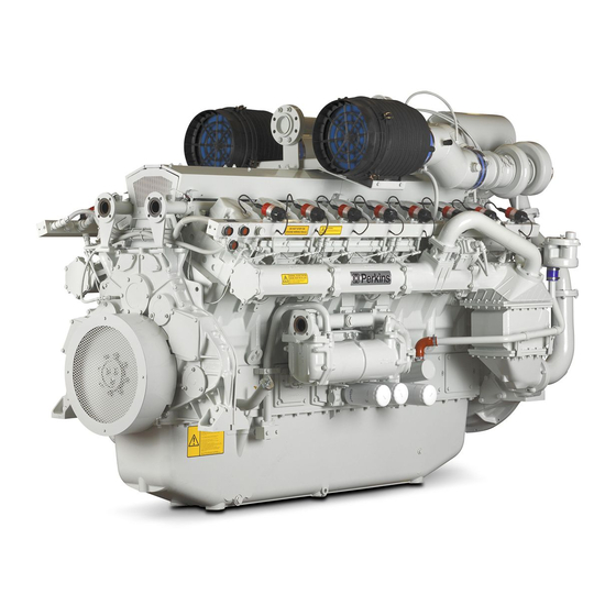
SEBU8190-02 Product Information Section Model Views and Specifications Product Information Section Model Views and Specifications i02415298 Model View Illustrations The illustrations show various typical features of 4000 Series TRS Engine. The illustrations do not show all of the options that are available. - Page 21 SEBU8190-02 Product Information Section Model View Illustrations Illustration 19 g01207301 Typical example (1) Air filter (5) Water temperature regulator (9) Engine oil filters (2) Governor control unit (6) Oil filler cap (10) Relay (3) Fuses for the ignition system (7) Alternator (11) Starting motor (4) Ignition (8) Oil level gauge (dipstick)
- Page 22 Any change in the composition of the gas may require a change to the venturi. The Perkins Engines were developed in order to The venturi is located in the gas mixer body provide gas engines for generator set applications.
- Page 23 SEBU8190-02 Product Information Section Specifications The air/fuel ratio is adjustable by the main adjustment • A water temperature regulator (thermostat) that screw. This screw is located on the gas mixer body controls the system for the charge cooler before the venturi. This is the only means of adjusting the exhaust emissions at full load.
- Page 24 SEBU8190-02 Product Information Section Specifications Table 1 4006 Engine Specifications Rated rpm 1500 Cylinders and arrangement In-line six cylinders Bore 160 mm (6.2992 inch) Stroke 190 mm (7.4803 inch) Displacement 22.9 L (1397.4436 in Compression ratio 12:1 Aspiration Turbocharged Rotation (flywheel end) Counterclockwise Inlet valve lash (cold) 0.40 mm (0.0157 inch)
- Page 25 SEBU8190-02 Product Information Section Specifications (Table 2, contd) Exhaust valve lash (cold) 0.40 mm (0.0157 inch) Firing order 1,4,7,6,8,5,2,3 Piston Positions for Valve Lash Setting Table 3 The six cylinder engine Set the bridge adjustment and set valve Top Center Position Engine cylinder with valves on the rock lash.
-
Page 26: Product Identification Information
SEBU8190-02 Product Information Section Product Identification Information Product Identification Perkins dealers and Perkins distributors require all of these numbers to determine the components that Information were included in the engine. This permits accurate identification of replacement part numbers. i08260717 Serial Number Plate... - Page 27 SEBU8190-02 Product Information Section Plate Locations and Film Locations Illustration 24 g01212991 Location of the serial number plate for in-line engines The serial number plate (1) on an in-line engine is on the right side of the cylinder block. See Illustration 24...
-
Page 28: Operation Section
If alterations are made, i07474450 ensure that proper lifting devices are provided. Consult your Perkins dealer for information regarding Product Lifting fixtures for proper engine lifting. i04823376... -
Page 29: Gauges And Indicators
Determine and correct the cause of any significant change in the readings. Consult your Perkins dealer or your Perkins distributor for assistance. NOTICE If no oil pressure is indicated, STOP the engine. If maximum coolant temperature is exceeded, STOP the engine. -
Page 30: Features And Controls
• Achieving optimum service life for the engine into the engine and the altitude derate. Contact your Perkins distributor or Perkins dealer for more If the air/fuel ratio is not appropriate for the fuel and information. - Page 31 SEBU8190-02 Operation Section Alarms and Shutoffs The electronic ignition system provides control for the The detonation system operates by measuring following activities: vibrations on the crankcase. The signal is processed in order to eliminate normal engine vibrations. If • Ignition timing detonation above a predetermined level is detected the engine timing is retarded.
- Page 32 SEBU8190-02 Operation Section Control Panel • Conditions which cause each control to function • Resetting procedure that is required before starting the engine Testing Alarms and Shutoffs Alarms must function properly in order to provide timely warning to the operator. Shutoffs help to prevent damage to the engine.
-
Page 33: Engine Starting
SEBU8190-02 Operation Section Engine Starting Engine Starting • Check the coolant level. Observe the coolant level in the header tank (if equipped). Maintain the coolant level to the “FULL” mark on the header i08259067 tank. Before Starting Engine • If the engine is not equipped with a header tank, maintain the coolant level within 13 mm (0.5 inch) of the bottom of the filler pipe. - Page 34 SEBU8190-02 Operation Section Starting the Engine Consult your Perkins dealer for more information on 1. The starting and the stopping of the engine must the starting aids that are available for cold weather be on no load. starting. 2. The procedure for starting and stopping a radiator...
- Page 35 SEBU8190-02 Operation Section Starting with Jump Start Cables 6. Start the engine. Refer to the engine starting 2. The engine is now operating. procedure and refer to OEM in order to start the Operation of the Generator Set engine. Control Panel Engine Starting Procedure For information on operation for a specific generator Note: The starting procedure may differ because of...
-
Page 36: Engine Operation
SEBU8190-02 Operation Section Engine Operation Engine Operation i02428569 Engine Operation Proper operation and maintenance are key factors in attaining the maximum service life and economy for the engine. Follow the instructions in this Operation and Maintenance Manual in order to minimize operating costs and maximize the service life of the engine. -
Page 37: Engine Stopping
SEBU8190-02 Operation Section Engine Stopping Engine Stopping 2. With the engine stopped, switch off the ignition and switch off the governor. 3. If an overspeed occurs, switch off the ignition, the i02428635 gas valve and the governor.. Emergency Stopping 4. If another engine fault occurs switch off the gas valve. - Page 38 SEBU8190-02 Operation Section After Stopping Engine • Perform all required periodic maintenance on all driven equipment. Refer to the instructions that are provided by the OEM of the driven equipment.
-
Page 39: Maintenance Section
SEBU8190-02 Maintenance Section Refill Capacities Maintenance Section (Table 9, contd) The Total Lubrication System includes the capacity for the Crankcase Oil Sump plus the capacity of factory installed oil fil- ters and other filters added to the lubrication system. Enter the Refill Capacities value for the capacity of the Total Lubrication System in this row. - Page 40 SEBU8190-02 Maintenance Section Fluid Recommendations Water (Table 11, contd) The Total Cooling System capacity includes the capacity of the Water is used in the cooling system to transfer heat. Engine plus the External System. Enter the value for the ca- pacity of the Total Cooling System in this row.
- Page 41 • Freezing • SCA Supplement Coolant Additive, • Cavitation of the water pump concentrated inorganic inhibitor package For optimum performance, Perkins recommends a • ASTM American Society for Testing and 50 percent by volume of glycol in the finished coolant Materials (also referred to as 1:1 mixture).
- Page 42 Correct additions to the Extended Life level of corrosion, boiling, and freezing protection as Coolant ELC or ELI. Perkins recommends a 6 percent to 8 percent concentration of SCA in those cooling systems. Distilled water or deionized water is NOTICE preferred.
- Page 43 To change from heavy-duty antifreeze to the Perkins 8. Repeat Steps 6 and 7 until the system is ELC, perform the following steps: completely clean. 9. Fill the cooling system with the Perkins Premixed NOTICE Care must be taken to ensure that all fluids are con- ELC.
- Page 44 Perkins Extended Life Inhibitor (ELI) is water-based coolant that does not contain glycol. Perkins ELI is for applications that do not require freeze protection. Exceptions are listed here. Failure to follow these recommendations can or will result in failures.
- Page 45 ELI into a clean container and mix thoroughly by Mixing Perkins ELI and Perkins ELC manual stirring or mechanical agitation. Since Perkins ELI and Perkins ELC are based on the If the preferred method cannot be performed, a same corrosion inhibitor technology, Perkins ELI can Perkins ELI mixture can be made by adding Perkins be mixed with Perkins ELC.
- Page 46 The size of the cooling system determines the amount of SCA that is needed. If using non Perkins coolants, refer to the coolant Use the equation that is in Table 19 to determine the manufacturer for information on a compatible SCA.
- Page 47 Some commercial cooling system cleaners can be Standard type and Quick Flush type, both types can acceptable quality water. Run the engine for 20 be used in all Perkins engine cooling systems. minutes and then drain the water. Consult your Perkins distributor for further guidance.
- Page 48 SCA that is required for maintenance, In engine cooling systems that use water alone, if necessary. Perkins recommends the use of SCA. SCA helps to prevent the following conditions from occurring: Note: Specific engine applications may require maintenance practices to be periodically evaluated to •...
- Page 49 Minimum TBN and maximum TAN will need to be agreed with the oil supplier prior to testing. It is important to work with an oil supplier or Perkins distributor to select the most appropriate oil based on your application.
- Page 50 • Mine gas • Lower calorific value The gas specification requirements are to be used as a guide only. Perkins require a full gas analysis to be • Methane number supplied at the inquiry stage of an engine order. Engine rating depends on the low calorific value of •...
- Page 51 10° to 50°C (50° to 122°F) The gas specification requirements are to be used as a guide only. Perkins require a full gas analysis to be supplied at the inquiry stage of an engine order. Engine rating depends on the methane number and the low calorific value of the fuel and may be adapted to suit the specifics of the fuel.
-
Page 52: Maintenance Interval Schedule (Engines Powered By Natural Gas Only)
For other gases, “ Engine Oil Sample - Obtain“ ....70 consult Perkins Applications Engineering (Stafford) for more information. - Page 53 SEBU8190-02 Maintenance Section Engines Powered by Natural Gas Only “ Engine Speed/Timing Sensor - Clean/Inspect“ . . 71 Every 3000 Service Hours or 2 Years “ Cooling System Coolant - Change“ ... 59 Every 4000 Service Hours “...
- Page 54 Maintenance Section Alternator - Inspect i02322311 Alternator - Inspect Perkins recommends a scheduled inspection of the alternator. Inspect the alternator for loose connections and correct battery charging. Check the ammeter (if equipped) during engine operation in order to ensure correct battery performance and/or correct performance of the electrical system.
- Page 55 SEBU8190-02 Maintenance Section Alternator and Fan Belts - Replace i08260849 Alternator and Fan Belts - Replace Alternator Illustration 29 g01222934 Typical example 6. Tension the belt. Apply pressure of 4.3 to 8.7 N (1 to 1.9 lb) between the two pulleys (7). The total deflection of the belt should not exceed 2.75 mm (0.10 inch).
- Page 56 SEBU8190-02 Maintenance Section Battery - Replace 8. Restore the electrical supply to the engine. 8. Restore the electrical supply to the engine. Fan Drive Belts i02429553 Battery - Replace Batteries give off combustible gases which can explode. A spark can cause the combustible gases to ignite.
-
Page 57: Battery Electrolyte Level - Check
SEBU8190-02 Maintenance Section Battery Electrolyte Level - Check i02747977 i02450196 Battery Electrolyte Level - Control Panel - Inspect Check Inspect the condition of the panel. If a component is damaged, ensure that the component is repaired or When the engine is not run for long periods of time or that the component is replaced. - Page 58 1. Stop the engine and allow the engine to cool. Isolate the electrical supply to the engine. Remove For information regarding the disposal and the the drain plug (1) recycling of used coolant, consult your Perkins distributor. Flush 1. Flush the cooling system with clean water to remove any debris.
-
Page 59: Cooling System Coolant - Change
2. If equipped, loosen the vent screw (3). Fill the Operate the engine until the temperature reaches cooling system with Perkins ELC. Refer to the 49 °C to 66 °C (120 °F to 150 °F). Operation and Maintenance Manual, “Fluid Recommendations”... - Page 60 SEBU8190-02 Maintenance Section Cooling System Coolant - Change NOTICE Keep all parts clean from contaminants. Contaminants may cause rapid wear and shortened component life. Note: Refer to the OEM for information on cogeneration engines. Clean the cooling system and flush the cooling system before the recommended maintenance interval if the following conditions exist: •...
- Page 61 The full distil- lation procedure is the only method acceptable by Perkins to reclaim the coolant. For information regarding the disposal and the recycling of used coolant, consult your Perkins distributor. Flush 1. Flush the cooling system with clean water to remove any debris.
-
Page 62: Cooling System Coolant - Test/Add
SEBU8190-02 Maintenance Section Cooling System Coolant - Test/Add 7. Install power to the engine. Start the engine and 3. Allow the engine to cool until the temperature is operate the engine. Inspect the cooling system for below 60 °C (140 °F). leaks. - Page 63 If the temperature begins to rise, reduce the interval for inspecting the damper. If the temperature of the damper reaches 100 °C (212 °F), consult your Perkins dealer. Inspect the damper for evidence of dents, cracks, and leaks of the fluid.
-
Page 64: Cylinders - Inspect
Photographic documentation or video documentation is also • Damaged parts recommended. Consult your Perkins dealer for information on available borescopes. Perform any maintenance that is recommended by the OEM of the driven equipment. Refer to the... - Page 65 SEBU8190-02 Maintenance Section Engine Air Cleaner Element - Replace Note: Ensure that dirt can not enter the air filter i02450440 assembly. Engine Air Cleaner Element - 3. Install a new element into the air filter assembly. Replace Install the cover (2) and install the washer and wing nut (3).
- Page 66 SEBU8190-02 Maintenance Section Engine Air Precleaner - Clean 1. Remove the precleaner from the air filter assembly and wash the precleaner. Note: Ensure that dirt can not enter the air filter assembly. 2. Ensure that the precleaner is clean and dry. Install the precleaner.
-
Page 67: Engine Mounts - Check
SEBU8190-02 Maintenance Section Engine Mounts - Check 7. Ensure that the seal in the cover (2) is free from damage. If necessary, replace the seal. 8. Align the cover (2) with the dowel (5). Install the cover to the breather body (4). 9. - Page 68 SEBU8190-02 Maintenance Section Engine Oil - Change i02468905 Engine Oil - Change Note: Refer to the Operation and Maintenance Manual, “Engine Oil Sample - Obtain” before performing maintenance. Do not drain the engine lubricating oil when the engine is cold. As the engine lubricating oil cools, suspended waste particles settle on the bottom of the oil pan.
- Page 69 SEBU8190-02 Maintenance Section Engine Oil Filter - Change 5. Clean any spillage of engine oil. i02472515 Engine Oil Filter - Change Note: Refer to the Operation and Maintenance Manual, “Engine Oil Sample - Obtain” before performing maintenance. Illustration 48 g02775859 Typical example The changeover valve (1) has three positions.
- Page 70 SEBU8190-02 Maintenance Section Engine Oil Sample - Obtain In order to determine the optimum program for the oil and filter service, use the oil analysis program that follows. Initiating an Oil analysis Program The oil sample must be taken from the mean level in the engine oil pan.
-
Page 71: Engine Speed/Timing Sensor - Clean/Inspect
SEBU8190-02 Maintenance Section Engine Protective Devices - Check Engine Speed Sensor Note: Perkins Engines Stafford must agree to the maintenance schedule. i02430590 Engine Protective Devices - Check Alarms and shutoffs must function properly. Alarms provide timely warning to the operator. Shutoffs help to prevent damage to the engine. - Page 72 NOTICE Only qualified service personel should perform this maintenance. Refer to the Service Manual or your au- thorized Perkins dealer or your Perkins distributor for the complete valve lash adjustment procedure. Operation of Perkins engines with incorrect valve lash can reduce engine efficiency, and also reduce engine component life.
- Page 73 Repair the components or replace the components if any of the following conditions occur: • Damage • Cracks • Leaks • Loose connections Consult your Perkins dealer for assistance. i08253393 Fan Drive Pulley - Check Illustration 54 g01238305 (4008-30 Engine Only) 3.
-
Page 74: Gas Pressure Regulator - Check
SEBU8190-02 Maintenance Section Gas Pressure Regulator - Check • For the service of the fuel filter on the low pressure Due to extreme temperature changes, the hose will heat set. Heat setting causes hose clamps to loosen. gas fuel system, refer to the OEM for information. This can result in leaks. - Page 75 SEBU8190-02 Maintenance Section Ignition System Spark Plugs - Inspect/Replace 10. Start the engine. Inspect the cooling system for Install a new sealing washer (3) before installing the old spark plug. leaks. 1. Clean the spark plug by using a nylon brush. i08260731 Ignition System Spark Plugs - Inspect/Replace...
-
Page 76: Ignition System Timing - Check/Adjust
• Rotating the screw (2) counterclockwise retards the ignition timing. Note: For engines that are installed with a detonation sensor, the timing is controlled by the detonation system. Contact your Perkins distributor or Perkins dealer for more information. -
Page 77: Inlet Air System - Inspect
The condition of Overhaul (In-Frame) components is inspected. Those components are replaced, if necessary. Your Perkins dealer can provide these services and Scheduling an In-Frame Overhaul components. Your Perkins dealer can ensure that the components are operating within the appropriate specifications. - Page 78 • Pistons If you elect to perform an overhaul without the • Transformers services of a Perkins distributor, be aware of the following recommendations. Replacing of Components Replace the following components during the major overhaul.
- Page 79 The condition of these components will determine the period of the major overhaul. • Inspection of all the parts that are visible during Contact your Perkins distributor or Perkins dealer for the disassembly more information. • Replacement of the seals and gaskets that are...
-
Page 80: Turbocharger - Inspect
Turbocharger - Inspect Your Perkins dealer can provide the parts that are needed to rebuild the engine at the least possible cost. Periodic inspection and cleaning are recommended for the turbochargers. -
Page 81: Water Pump - Inspect
SEBU8190-02 Maintenance Section Walk-Around Inspection i02484850 Walk-Around Inspection NEVER use a flame to check for gas leaks. Use a gas detector. An open flame can ignite mixtures of air and fuel. Inspect the Engine for Leaks and This will cause explosion and/or fire which could result in severe personal injury or death. - Page 82 SEBU8190-02 Maintenance Section Water Temperature Regulator - Replace 3. If the valve does not open, or the valve does not i08260745 open to the full amount discard the old element. Water Temperature Regulator - Replace the Water Temperature Replace Regulator (Thermostat) 1.
-
Page 83: Reference Information Section
Maintenance records are a key element of a maintenance program that is well managed. Accurate maintenance records can help your Perkins dealer to fine tune the recommended maintenance intervals in order to meet the specific operating situation. This should result in a lower engine operating cost. - Page 84 SEBU8190-02 Reference Information Section Valve Data Sheet (Table 25, contd) i02484853 Valve Data Sheet Table 26 Engine Model Serial Number Service Hours Valve Location Cylinder Cylinder Current Measure Reset size Wear Pressure Inlet Inlet Exhaust Exhaust Inlet Inlet Exhaust (continued)
- Page 85 Inlet Inlet Exhaust Exhaust i02484854 Warranty Information The engine installation and the service interval for the engine must be approved. The engine must be operated with the approved fuel, lubricant and coolant. Refer to Perkins Engines Stafford for more information.
-
Page 86: Index
SEBU8190-02 Index Section Index Additional Messages ........11 Driven Equipment - Check ......64 After Starting Engine ........35 Driven Equipment - Inspect/Replace/ After Stopping Engine ........37 Lubricate............64 Alarms and Shutoffs ........31 Testing Alarms and Shutoffs......32 Alternator - Inspect .......... 54 Electrical System.......... - Page 87 SEBU8190-02 Index Section Fan Drive Pulley - Check (4008-30 Engine Ignition System Spark Plugs - Inspect/ Only) .............. 73 Replace ............75 Features and Controls........30 Check the Spark Plug and Adjust the Spark Fire Prevention and Explosion Prevention..16 Plug ............
- Page 88 SEBU8190-02 Index Section Scheduling an In-Frame Overhaul ....77 Rotating Shaft Hand Crush Hazard..... 10 Overhaul (Major) ..........77 Universal Warning ......... 8 Major Overhaul Information ......78 Safety Section ........... 6 Scheduling a Major Overhaul ...... 77 Sensors and Electrical Components....30 Overhaul (Top End) .........
- Page 89 Product and Dealer Information Note: For product identification plate locations, see the section “Product Identification Information” in the Operation and Maintenance Manual. Delivery Date: Product Information Model: Product Identification Number: Engine Serial Number: Transmission Serial Number: Generator Serial Number: Attachment Serial Numbers: Attachment Information: Customer Equipment Number: Dealer Equipment Number:...
- Page 90 SEBU8190 ©2022 Perkins Engines Company Limited All Rights Reserved May 2022...
Need help?
Do you have a question about the 4006 TRS Gas and is the answer not in the manual?
Questions and answers