
Related Manuals for Perkins 4006-23


Summary of Contents for Perkins 4006-23
- Page 1 SEBU9077-01 (en-us) September 2016 Operation and Maintenance Manual 4006-23 and 4008-30 Industrial Engines SD8 (Engine) SD6 (Engine) DGBH (Engine)
- Page 2 These changes can affect the service that is given to the product. Obtain the complete and most current information before you start any job. Perkins dealers or Perkins distributors have the most current information available. When replacement parts are required for this product Perkins recommends using Perkins replacement parts.
-
Page 3: Table Of Contents
SEBU9077-01 Table of Contents Table of Contents Warranty Section Warranty Information........83 Foreword ............4 Index Section Safety Section Index..............84 Safety Messages..........5 General Hazard Information......9 Burn Prevention..........12 Fire Prevention and Explosion Prevention..13 Crushing Prevention and Cutting Prevention.. 15 Mounting and Dismounting ...... -
Page 4: Foreword
Operation Operation and Maintenance Manual except for the interval and the maintenance items in that interval. Major repairs should only be carried out by Perkins Operating techniques outlined in this manual are authorized personnel. Your Perkins dealer or your basic. They assist with developing the skills and... -
Page 5: Safety Section
Replace any warning sign that is damaged or missing. If a warning sign is attached to a part of the engine that is replaced, install a new warning sign on the replacement part. Your Perkins distributor can provide new warning signs. Illustration 1... - Page 6 SEBU9077-01 Safety Section Safety Messages Illustration 2 g06093786 (1) Universal warning label location (6) Rotating shaft hand crush hazard label (3) Hot surface label location location 1 Universal Warning Do not operate or work on this equipment unless you have read and understand the instructions and warnings in the Operation and Maintenance Manuals.
- Page 7 SEBU9077-01 Safety Section Safety Messages The hot surface warning labels (2) are located in two locations. The oil cooler and heat shield of the coolant rail. 4 Hot Fluid Under Pressure Illustration 4 g01393287 Do not use this surface as a step or platform. This surface may not support additional weight or may be slippery.
- Page 8 Ether warning label (4) is on the support bracket for positions. One label is on the end cover of the oil the air cleaners. cooler. Perkins recommends that the other hot fluid under pressure label is installed on the radiator, next 6 Rotating Shaft Hand Crush to the coolant filler cap.
-
Page 9: General Hazard Information
SEBU9077-01 Safety Section General Hazard Information The rotating shaft hand crush hazard label (5) is on • Never put maintenance fluids into glass the cover of the crankshaft vibration damper. containers. Glass containers can break. • Use all cleaning solutions with care. i06106934 General Hazard Information •... - Page 10 SEBU9077-01 Safety Section General Hazard Information Cautiously remove the following parts. To help • Disconnect the batteries when maintenance is prevent spraying or splashing of pressurized fluids, performed or when the electrical system is hold a rag over the part that is being removed. serviced.
- Page 11 Perkins equipment and replacement parts that are shipped from Perkins engine company limited are The removal of sulfur and other compounds in ultra- asbestos free. Perkins recommends the use of only low sulfur diesel fuel (ULSD fuel) decreases the genuine Perkins replacement parts. Use the following...
-
Page 12: Burn Prevention
SEBU9077-01 Safety Section Burn Prevention • Avoid brushing materials that contain asbestos. Always use leakproof containers when you drain fluids. Do not pour waste onto the ground, down a • Avoid grinding materials that contain asbestos. drain, or into any source of water. •... -
Page 13: Fire Prevention And Explosion Prevention
Personal injury, property damage, or engine damage could result. If the application involves the presence of combustible gases, consult your Perkins dealer and/ or your Perkins distributor for additional information about suitable protection devices. Remove all flammable combustible materials or conductive materials such as fuel, oil, and debris from the engine. - Page 14 SEBU9077-01 Safety Section Fire Prevention and Explosion Prevention Illustration 15 g00704059 Illustration 16 g00704135 Use caution when you are refueling an engine. Do Gases from a battery can explode. Keep any open not smoke whilst you are refueling an engine. Do not flames or sparks away from the top of a battery.
-
Page 15: Crushing Prevention And Cutting Prevention
Do not install any lines that are damaged. i04257031 Leaks can cause fires. Consult your Perkins distributor for replacement parts. Before Starting Engine Replace the parts if any of the following conditions are present: •... -
Page 16: Engine Starting
SEBU9077-01 Safety Section Engine Starting Use the Emergency Stop Button (if equipped) ONLY i06545901 in an emergency situation. Do not use the Engine Starting Emergency Stop Button for normal engine stopping. After an emergency stop, DO NOT start the engine until the problem that caused the emergency stop has been corrected. -
Page 17: Engine Electronics
The laptop computer is connected to the governor via an interface cable. The operating parameters for the governor should only be modified by a trained Perkins representative. Refer to the Special Instruction, “Pandoras Digital Governor” for more information. -
Page 18: Product Information Section
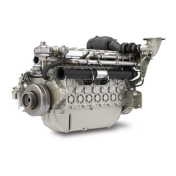
SEBU9077-01 Product Information Section Model Views Product Information Section Model Views i06681533 Model View Illustrations (Engine Views for the Six and Eight Cylinder 4000 Series Engines) The following model views show typical features of the engine. Due to individual applications, your engine may appear different from the illustrations. - Page 19 SEBU9077-01 Product Information Section Engine Views for the Six and Eight Cylinder 4000 Series Engines 4006-23 Engine Views Illustration 17 g06072657 Typical example (1) Twin air cleaners (3) Adjustment housing (5) Belts (2) Crankcase breather (4) Fan hub pulley The major engine differences on six cylinder engine to an eight cylinder engine are shown in illustration 17 .
- Page 20 SEBU9077-01 Product Information Section Engine Views for the Six and Eight Cylinder 4000 Series Engines 4006-23 Radiator Illustration 18 g06072687 Typical example (1) Radiator lifting eyes (3) Radiator (5) Fuel cooler (2) Radiator pressurized filler cap (4) Radiator drain (6) Air charge cooler...
- Page 21 SEBU9077-01 Product Information Section Engine Views for the Six and Eight Cylinder 4000 Series Engines 4008-30 Engine Views Illustration 19 g06004723 Typical example (1) Twin air cleaners (7) Stop solenoid (13) Oil drain location (2) Electronic governor control unit (8) Oil filler cap (14) Oil filters (3) Oil cooler (9) Coolant pump...
- Page 22 SEBU9077-01 Product Information Section Engine Views for the Six and Eight Cylinder 4000 Series Engines Illustration 20 g06004738 Typical example (17) Twin turbochargers (19) Left side rear lifting eye (18) Right side rear lifting eye (20) Crankcase breather...
- Page 23 (3) Radiator (6) Fan belts (9) Fuel cooler i06681623 Engine Description The 4006-23 and the 4008-30 engines are available with turbocharged aftercooled aspiration. The 4006- 23 and the 4008-30 industrial engines are designed as a constant speed engine. Engine Specifications The front end of the engine is opposite the flywheel end of the engine.
- Page 24 SEBU9077-01 Product Information Section Engine Description Table 1 4006-23 Engine Specifications Engine efficiency, efficiency of emission controls, and engine performance depend on adherence to proper Number of cylinders In-line 6 cylinder operation and maintenance recommendations. Engine performance and efficiency also depend on Bore 160 mm (6.29920 inch)
-
Page 25: Product Identification Information
Illustration 24 g06016214 Typical example (1) Engine serial number plate Your Perkins distributor needs all the number from the plate when service information is required. Emission Label The emission label (2) is installed on the inlet manifold of the engine. -
Page 26: Operation Section
Alterations to the lifting eyes and/or the engine make the lifting eyes and the lifting fixtures obsolete. If alterations are made, ensure that correct lifting devices are provided. Consult your Perkins distributor for information regarding fixtures for correct engine lifting. - Page 27 SEBU9077-01 Operation Section 4006-23 and 4008-30 Engines Illustration 25 g06006861 Typical example (1) Rear lifting eye (2) Rear lifting eye (3) Front lifting eye Radiator Lifting Only Illustration 26 g06006867 Typical example (1) Radiator lifting eye (2) Radiator lifting eye...
- Page 28 Operation Section Engine Storage i03781209 Engine Storage Refer to Perkins Engine Company Limited, Stafford, ST16 3UB for information on engine storage. There are three different levels of engine storage. Level “A, B and C” . Level “ “ A ” ”...
-
Page 29: Features And Controls
SEBU9077-01 Operation Section Features and Controls Features and Controls i06518677 Monitoring System The engine is equipped with sensors or switches to monitor the following parameters: • Coolant temperature • Oil pressure • Intake manifold boost pressure • Engine speed • Engine overspeed The throttle control is also monitored and controlled. - Page 30 SEBU9077-01 Operation Section Sensors and Electrical Components Illustration 27 g06006910 Typical example (1) Coolant temperature switch (4) Oil pressure switch (7) Inlet manifold air pressure sensor (2) Stop solenoid (5) Starter relay (8) Electronic governor control unit (3) Alternator (6) Starting motor...
- Page 31 SEBU9077-01 Operation Section Sensors and Electrical Components Illustration 28 g06006921 Typical example (9) Oil pressure switch (10) Overspeed sensor...
-
Page 32: Engine Starting
SEBU9077-01 Operation Section Engine Starting Engine Starting The engine is now ready to run. i06521690 i06520585 Starting the Engine Before Starting Engine Normal Engine Starting Procedure Before the engine is started, perform the required daily maintenance and any other periodic maintenance that is due. -
Page 33: Engine Operation
Fuel Conservation Practices The efficiency of the engine can affect the fuel economy. Perkins design and technology in manufacturing provides maximum fuel efficiency in all applications. Follow the recommended procedures in order to attain optimum performance for the life of the engine. -
Page 34: Engine Stopping
SEBU9077-01 Operation Section Engine Stopping Engine Stopping • Check the crankcase oil level. Maintain the oil level between the “MIN” mark and the “MAX” mark on the engine oil level gauge. i02415227 • If necessary, perform minor adjustments. Repair Stopping the Engine any leaks from the low pressure fuel system and from the cooling, lubrication or air systems. -
Page 35: Maintenance Section
• Overheating of the engine Cooling System • Foaming of the coolant Table 4 NOTICE 4006-23 Engine and Engine with Radiator Never operate an engine without water temperature regulators in the cooling system. Water temperature Engine Only 36 L (9.5 US gal) regulators help to maintain the engine coolant at the proper operating temperature. - Page 36 Table 6 • Cavitation of the water pump Table 6 For optimum performance, Perkins recommends a 1:1 mixture of a water/glycol solution. Acceptable Water Note: Use a mixture that will provide protection...
- Page 37 Extended Life Coolant contains organic corrosion inhibitors and antifoam • SCA Supplement Coolant Additive agents with low amounts of nitrite. Perkins ELC has been formulated with the correct amount of these additives to provide superior corrosion protection for • ASTM American Society for Testing and all metals in engine cooling systems.
- Page 38 Check the antifreeze (glycol concentration) to ensure adequate protection against boiling or freezing. 6. Fill the cooling system with the Perkins Premixed Perkins recommends the use of a refractometer for checking the glycol concentration. A hydrometer ELC. Operate the engine. Ensure that all coolant should not be used.
- Page 39 Table 13 is an example for using the equation that is in Table 12 . NOTICE Every attempt is made to provide accurate, up-to- date information. By use of this document you agree that Perkins Engines Company Limited is not respon- sible for errors or omissions.
- Page 40 The fuel must meet the minimum requirements that are stated in Table 14 . NOTICE The footnotes are a key part of the Perkins Specifica- tion for Distillate Diesel Fuel Table. Read ALL of the footnotes. Table 14...
- Page 41 Note: The owner and the operator of the engine has NOTICE the responsibility of using the fuel that is prescribed Operating with fuels that do not meet the Perkins rec- by the Environmental Protection Agency (EPA) and ommendations can cause the following effects: Start- other appropriate regulatory agencies.
- Page 42 15 °C (59 °F). NOTICE The fuels system has been qualified with fuel having Perkins recommends a value of density of 841 kg/m3 lubricity up to 0.46 mm (0.01811 inch) wear scar di- to obtain the correct power output. Lighter fuels are ameter as tested by “ISO 12156-1”.
- Page 43 • “MIL-DTL-38219 (USAF) (JP7)” requirement appropriate lubricity additive can be • “NATO XF63” used to enhance the lubricity of the fuel. Perkins Diesel Fuel Conditioner is the approved additive refer • “ASTM D1655 JET A” to “Perkins Diesel Fuel Conditioner”.
- Page 44 Protection Agency (EPA) and European Certification biodiesel or biodiesel blends is related to the fuels. Perkins does not certify engines on any other typically lower volatility of biodiesel. In cylinder fuel. The user of the engine has the responsibility of...
- Page 45 If biodiesel or biodiesel blends of fuel are to be used, fuels. Perkins require the use of Perkins fuel cleaner. For more information on the use of biodiesel and biodiesel blends refer to “Biodiesel Fuel”.
- Page 46 500 ppm water or less. • Perkins recommends the use of bulk fuel filter / coalescer units which clean the fuel of both particulate contamination and water in a single...
- Page 47 “EMA Recommended Guideline on Diesel Engine promotes the delivery of clean fuel. Fuel filtration Oil”. In addition to Perkins definitions, there are other can be installed at each transport stage to keep definitions that will be of assistance in purchasing the fuel clean.
- Page 48 SEBU9077-01 Maintenance Section Engine Oil Specification Table 15 Minimum Oil Specification for 4008-30 and the 4006-23 Industrial Engines Preferred Oil Specification API CI-4 ECF-2 Minimum Oil Specification API CH-4 ECF 1 Lubricant Viscosity Recommendations Aftermarket Oil Additives for Direct Injection (DI) Diesel Engines Perkins does not recommend the use of aftermarket additives in oil.
- Page 49 SEBU9077-01 Maintenance Section Engine Oil Specification • The Wear Rate Analysis monitors the wear of the engines metals. The amount of wear metal and type of wear metal that is in the oil is analyzed. The increase in the rate of engine wear metal in the oil is as important as the quantity of engine wear metal in the oil.
-
Page 50: Maintenance Interval Schedule
SEBU9077-01 Maintenance Section Maintenance Interval Schedule “ Belts - Inspect/Adjust/Replace”....55 i06682467 Maintenance Interval Schedule “ Belts - Inspect/Adjust/Replace”....56 “... -
Page 51: Alternator Pulley - Check
Make repairs, if necessary. i02322311 Alternator - Inspect Perkins recommends a scheduled inspection of the alternator. Inspect the alternator for loose connections and correct battery charging. Check the ammeter (if equipped) during engine operation in order to ensure correct battery performance and/or correct performance of the electrical system. -
Page 52: Battery - Replace
SEBU9077-01 Maintenance Section Battery - Replace i02322315 i02747977 Battery - Replace Battery Electrolyte Level - Check When the engine is not run for long periods of time or when the engine is run for short periods, the batteries Batteries give off combustible gases which can explode. -
Page 53: Battery Or Battery Cable - Disconnect
SEBU9077-01 Maintenance Section Battery or Battery Cable - Disconnect Inspection i02323088 Battery or Battery Cable - 1. Isolate the electrical supply to the engine. Disconnect 2. Visible inspect fan guards for ware or damage. Repair as necessary. The battery cables or the batteries should not be removed with the battery cover in place. - Page 54 SEBU9077-01 Maintenance Section Fan Drive Belts for 4008-30 Only 4. Inspect the belts (1) for cracks. Inspect the belts 5. Ensure that the electrical supply to the engine is for contamination. If necessary, replace the belts. isolated. Install the guards. Refer to “Replacement”...
-
Page 55: Belts - Inspect/Adjust/Replace
Repair as necessary. Remove the fan guards (1). Belts - Inspect/Adjust/Replace 3. Inspect the belts for cracks, splits, glazing, grease, displacement of the cord and evidence of fluid (4006-23 Engine Only) contamination. If necessary, replace the belts, refer to “Replace” for more information. S/N: SD61–Up... -
Page 56: Belts - Inspect/Adjust/Replace
SEBU9077-01 Maintenance Section Belts - Inspect/Adjust/Replace 8. Install guards (1) and restore electrical power to the engine. Replace Refer to “Disassembly and Assembly Manual”V-Belts (Fan Drive V-Belts) - Remove and Install for more information. i06729752 Belts - Inspect/Adjust/Replace (Alternator Belt) Inspection 1. - Page 57 SEBU9077-01 Maintenance Section Alternator Belt Illustration 40 g01239310 4. Apply 15.6 N (3.5 lb) of pressure at point (X). The total deflection should not exceed 1.5 mm (0.06 inch). Replace the belt if the total deflection exceeds Illustration 41 g06018464 1.5 mm (0.06 inch).
-
Page 58: Cooling System Coolant (Elc) - Change
SEBU9077-01 Maintenance Section Cooling System Coolant (ELC) - Change Drain 5. Install the guards and restore the electrical supply to the engine. i06729765 Pressurized System: Hot coolant can cause seri- Cooling System Coolant (ELC) ous burns. To open the cooling system filler cap, stop the engine and wait until the cooling system - Change components are cool. - Page 59 The full distil- 2. Fill the cooling system with Perkins (ELC). Refer to lation procedure is the only method acceptable by the Operation and Maintenance Manual, “Fluid Perkins to reclaim the coolant.
-
Page 60: Cooling System Coolant Level - Check
2. Maintain the coolant level within 25 mm (1.0 inch) of the bottom of the filler pipe. Cooling System Coolant Extender (ELC) - Add For Perkins ELC to achieve 12000 hours an extender must be added at 6000 hours. For a suitable extender, contact your Perkins distributor. i02415245... -
Page 61: Engine - Clean
SEBU9077-01 Maintenance Section Driven Equipment - Check Inspect the dampers for signs of damage, fluid NOTICE leakage, or heat discoloration. Failure to protect some engine components from washing may make your engine warranty invalid. Al- For more information on inspection the vibration low the engine to cool for 1 hour before washing the dampers, refer to Systems Operation Testing and engine. -
Page 62: Engine Air Cleaner Service Indicator - Inspect
Illustration 49 g06073787 4008-30 1. Both the end caps (6) on the 4006-23 engine are secured by one central nut (5). Ensure that both 1. Isolate the electrical supply to the engine. filter elements (not shown) are replaced at the 2. -
Page 63: Engine Crankcase Breather - Clean
If the service indicator does not reset easily, the service indicator should be replaced. Note: The service indicator may need to be replaced frequently in environments that are severely dusty. i06682477 Engine Crankcase Breather - Clean (4006-23 Engine Only) S/N: SD61–Up... -
Page 64: Engine Crankcase Breather - Clean
Maintenance Section Engine Crankcase Breather - Clean Note: The maintenance and maintenance period for i06682626 the 4006-23 engine is different from the maintenance Engine Crankcase Breather - and maintenance period for the 4008-30 engine. Clean 1. Isolate the electrical supply to the engine. -
Page 65: Engine Oil Level - Check
SEBU9077-01 Maintenance Section Engine Mounts - Inspect i02415257 Engine Mounts - Inspect Misalignment of the engine and the driven equipment will cause extensive damage. Excessive vibration can lead to misalignment. Excessive vibration of the engine and the driven equipment can be caused by the following conditions: •... -
Page 66: Engine Oil Sample - Obtain
Hot oil and hot components can cause personal develop a service program for the engine. injury. Do not allow hot oil or hot components to contact the skin. Note: Perkins Engines Stafford must agree to the maintenance schedule. NOTICE Obtain the Sample and the... - Page 67 SEBU9077-01 Maintenance Section Engine Oil and Filter - Change Failure to follow this recommended procedure will 3. Install a new sealing washer to the drain plug (3). cause the waste particles to be recirculated through Install the drain plug to the engine oil pan. Tighten the engine lubrication system with the new oil.
-
Page 68: Engine Valve Lash - Inspect/Adjust
Refer to the Service Manual or your au- oil level. Maintain the oil level between the “MIN” thorized Perkins dealer or your Perkins distributor for and “MAX” marks on the engine oil level gauge. the complete valve lash adjustment procedure. -
Page 69: Fuel System - Prime
Perkins distributor for the complete proce- dure in order to inspect or adjust the fuel injectors. Operation of Perkins engines with fuel injectors that have not been inspected or adjusted can reduce en- gine efficiency, and also reduce engine component life. -
Page 70: Fuel System Filter - Replace
SEBU9077-01 Maintenance Section Fuel System Filter - Replace Illustration 61 g06010017 1. Ensure that there is an adequate level of fuel in the NOTICE fuel tank. If equipped, ensure that the fuel supply Ensure that the engine is stopped and the battery is valve is in the ON position. -
Page 71: Fuel Tank Water And Sediment - Drain
SEBU9077-01 Maintenance Section Fuel System Primary Filter/Water Separator - Drain NOTICE Ensure that the engine is stopped before any servic- ing or repair is performed. NOTICE The water separator can be under suction during nor- mal engine operation. Ensure that the drain valve is tightened securely to help prevent air from entering the fuel system. -
Page 72: Fuel Transfer Pump (Lift Pump) - Inspect
SEBU9077-01 Maintenance Section Fuel Transfer Pump (Lift Pump) - Inspect Fuel Tank If a bulk storage tank has been refilled or moved recently, allow adequate time for the sediment to Fuel quality is critical to the performance and to the settle before filling the engine fuel tank. -
Page 73: Hoses And Clamps - Inspect/Replace
The coolant system and the hoses for the coolant Contact with high pressure fuel may cause fluid system are not usually supplied by Perkins. The penetration and burn hazards. High pressure fuel following text describes a typical method of replacing spray may cause a fire hazard. - Page 74 SEBU9077-01 Maintenance Section Hoses and Clamps - Inspect/Replace Pressurized System: Hot coolant can cause seri- ous burns. To open the cooling system filler cap, stop the engine and wait until the cooling system components are cool. Loosen the cooling system pressure cap slowly in order to relieve the pressure.
- Page 75 SEBU9077-01 Maintenance Section Hoses and Clamps - Inspect/Replace 10. Start the engine. Inspect the cooling system for leaks. Clamps and V-Band Locations Illustration 65 g06117407 (1) Clamp torque 7 N·m (62 lb in)
- Page 76 SEBU9077-01 Maintenance Section Hoses and Clamps - Inspect/Replace Illustration 66 g06117430 (1) Clamp torque 7 N·m (62 lb in) (2) Clamp torque 9 N·m (79 lb in) (3) Clamp torque 10 N·m (88 lb in)
-
Page 77: Overhaul (Major)
Monitor the engine as the engine accumulates Scheduling a Major Overhaul service hours. Consult Perkins Engines Stafford about scheduling a major overhaul. The need for a major overhaul is determined by several factors: •... -
Page 78: Overhaul (Top End)
SEBU9077-01 Maintenance Section Overhaul (Top End) Note: The driven equipment may also require service Note: Generally, cylinder heads wear out at different when the engine is overhauled. Refer to the literature rates. Sometimes, servicing the cylinder heads at that is provided by the OEM of the driven equipment. different times may be the most economic decision. -
Page 79: Severe Service Application - Check
Hold the nozzle approximately 6 mm service life. (0.25 inch) away from the radiator fins. Slowly move Perkins engines are unable to identify all the factors the air nozzle in a direction that is parallel with the which can contribute to severe service operation, due radiator tube assembly. -
Page 80: Speed Sensor - Clean/Inspect
SEBU9077-01 Maintenance Section Speed Sensor - Clean/Inspect cold temperatures. Extremely hot intake air reduces 1. Isolate the electrical supply to the engine. engine performance. Quality of the air – The engine may be exposed to extended operation in an environment that is dirty or dusty, unless the equipment is cleaned regularly. -
Page 81: Walk-Around Inspection
SEBU9077-01 Maintenance Section Starting Motor - Inspect Inspect the starting motors for proper operation. Listen for grinding when the engine is started. Inspect the teeth of the starting motor pinions and the flywheel ring gear. Look for patterns of wear on the teeth. -
Page 82: Water Pump - Inspect
Excessive coolant leakage may indicate the need to replace a water pump. Refer to Operation and Maintenance Manual, “Water Pump - Inspect” for more information. If necessary, consult your Perkins dealer or your Perkins distributor. • Inspect the lubrication system for leaks at the front crankshaft seal, the rear crankshaft seal, the oil pan, the oil filters and the rocker cover. -
Page 83: Warranty Section
This engine may be covered by an Emissions Warranty. Consult your authorized Perkins dealer or distributor to determine if your engine is emissions certified and if your engine is subject to an Emissions... -
Page 84: Index
Engine Specifications ........23 Adjustment........... 57 Engine Electronics........... 17 Inspection ............ 56 System Description........17 Replacement..........57 Engine Lifting (4006-23 and 4008-30 Belts - Inspect/Adjust/Replace (Fan Drive Engines) ............26 Belts for 4008-30 Only)........53 Engine Lifting Only........26 Adjustment........... 54 Radiator Lifting Only ........ - Page 85 Six and Eight Cylinder 4000 Series Fuel Tank Water and Sediment - Drain ... 71 Engines) ............18 Drain the Water and the Sediment ....72 4006-23 Engine Views......... 19 Fuel Storage Tanks........72 4008-30 Engine Views......... 21 Fuel Tank ............. 72 4008-30 Radiator .........
- Page 86 SEBU9077-01 Index Section Scheduling a Major Overhaul ...... 77 Water Pump - Inspect........82 Overhaul (Top End) ......... 78 Scheduling a Top End Overhaul ....78 Top End Overhaul Information..... 78 Plate Locations and Film Locations ....25 Emission Label ..........25 Product Identification Information ....
- Page 87 Product and Dealer Information Note: For product identification plate locations, see the section “Product Identification Information” in the Operation and Maintenance Manual. Delivery Date: Product Information Model: Product Identification Number: Engine Serial Number: Transmission Serial Number: Generator Serial Number: Attachment Serial Numbers: Attachment Information: Customer Equipment Number: Dealer Equipment Number:...
- Page 88 ©2016 Perkins Engines Compony Limited All Rights Reserved September 2016...
Need help?
Do you have a question about the 4006-23 and is the answer not in the manual?
Questions and answers