
Related Manuals for Spectrex SharpEye 40/40UFL


Summary of Contents for Spectrex SharpEye 40/40UFL
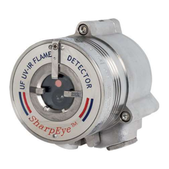
- Page 1 Model 40/40UFL Ultra Fast UV/IR Flame Detector User Guide 8200 Market Blvd, Chanhassen, MN 55317, USA Phone: +1 (973) 239 8398 Website: www.spectrex.net Email: spectrex.csc.rmtna@emerson.com...
- Page 3 “Act of God” which are above and beyond its control. SPECTREX will, upon receipt of any defective product, transportation prepaid, repair or replace it at its sole discretion if found to have been defective when shipped. Said repair or replacement is SPECTREX’S sole liability under this warranty and SPECTREX’S liability shall be limited to repair or replacement of the component found...
-
Page 5: Table Of Contents
Table of Contents Table of Contents .................... v List of Figures ....................ix List of Tables ....................x About this Guide ..................11 Release History ..................12 Glossary and Abbreviations ..............12 Notifications ..................14 Product Overview ..................15 Model and Types ................... 16 Features and Benefits ................ - Page 6 3.1.3 Spacing and Location ..............33 3.1.4 Environment .................. 33 Aiming the Detector: ................34 Unpacking the Product ................34 3.3.1 Checking the Product Type ............... 34 Required Tools ..................34 Certification Instructions ................ 35 3.5.1 Special Instructions for Safe Use ............35 3.5.2 General Instructions ................
- Page 7 Electrical Specifications ................53 A.2.1 Electrical Input Protection ..............54 Outputs ....................54 A.3.1 Electrical Interface ................54 A.3.2 Electrical Outputs ................55 A.3.3 Heated Optics ................. 56 Approvals..................... 57 A.4.1 Hazardous Area Approvals ............... 57 A.4.2 Functional Approvals ............... 57 Mechanical Specifications ...............
- Page 8 D.1.3 Operating Instructions ..............70 D.1.4 Range ................... 71 D.1.5 Charging the Battery ............... 71 D.1.6 Battery Replacement ............... 72 Technical Specifications ................. 73 D.2.1 General ..................73 D.2.2 Electrical ..................73 D.2.3 Physical ..................73 D.2.4 EMI Compatibility ................73 Tilt Mount ....................
-
Page 9: List Of Figures
List of Figures Figure 1: Horizontal Field of View ................ 25 Figure 2: Vertical Field of View ................25 Figure 3: Indicator LED ..................27 Figure 4: Detector with Tilt Mount ............... 38 Figure 5: Tilt Mount Assembly ................39 Figure 6: Tilt Mount Assembly (dimensions in mm and inches) ........ - Page 10 List of Tables Table 1: Wiring Options ..................17 Table 2: Fuel Sensitivity Ranges ................24 Table 3: Immunity to False Alarm Sources ............26 Table 4: LED Indications ..................27 Table 5: Available Output Types ................28 Table 6: Detector Status ..................28 Table 7: Output Signals Versus Detector State ............
-
Page 11: About This Guide
About this Guide About this Guide This guide describes the SharpEye Model 40/40UFL Flame Detector and its features and provides instructions on how to install, operate, and maintain the detector. Note: This user guide should be read carefully by all individuals who have or will have responsibility for using, maintaining, or servicing the product. -
Page 12: Release History
About this Guide Release History Date Revision History Prepared by Approved by October 2012 First Release Ian Buchanan Eric Zinn March 2013 Second Release Ian Buchanan Eric Zinn August 2013 Third Release Ian Buchanan Eric Zinn May 2014 Fourth Release Ian Buchanan Eric Zinn February 2015... - Page 13 About this Guide Abbreviation/Term Meaning Internet Protocol Isopropyl Alcohol Infrared Refers to the 3 IR sensors in the VID Jet Fuel Light Emitting Diode Serial communications protocol using Master-Slave MODBUS messaging Not Applicable N.C. Normally Closed NFPA National Fire Protection Association N.O.
-
Page 14: Notifications
About this Guide Notifications This section explains and exemplifies the usage of warnings, cautions, and notes throughout this guide: Warning: This indicates a potentially hazardous situation that could result in serious injury and/or major damage to the equipment. Caution: This indicates a situation that could result in minor injury and/or damage to the equipment. -
Page 15: Product Overview
SPECTREX product warranty. All 40/40 series detectors include a heated optical window for improved performance in ice, snow, and condensation conditions. -
Page 16: Model And Types
Product Overview Model and Types The 40/40UFL UV/IR flame detector is provided in various configurations depending on: • Wiring options • Temperature ranges • Type of cable entries • Housing material type • Required approval The configuration detail is included in the product part number on the product label and takes the form: 40/40UFL-XXXXX, where XXXXX defines the model according to the above requirements. -
Page 17: Table 1: Wiring Options
Product Overview Table 1 describes the wiring options in detail. Table 1: Wiring Options Wiring Connections Provided Option Fault Alarm Analog 0–20mA Power Relay Relay RS-485 HART Output Sink N.C. N.O. Alarm Fault Analog Relay 0–20mA Power Relay RS-485 HART Output N.O., Source... -
Page 18: Features And Benefits
Product Overview Features and Benefits • UV/IR Dual Sensor • High Speed Response: 20msec response to flash fire • Built-In-Test (BIT): Automatic (see Built-In-Test (BIT) on page 31). • Heated Window: Prevents effects of ice, snow, and condensation. • Electrical Interface: •... -
Page 19: Detection Levels
Product Overview 2.3.2 Detection Levels Simultaneous detection of radiation in both the UV and the IR channels, with an intensity that exceeds the detector’s preset Warning level results in a Warning signal. Simultaneous detection of radiation in both the UV and the IR channels, with an intensity that exceeds the detector’s preset Alarm level results in an Alarm signal. -
Page 20: Rs-485 Modbus
Product Overview 2.3.5 RS-485 Modbus For more advanced communications, the 40/40UFL detector has an RS-485 Modbus-compatible output that provides data communication from a network (up to 247 detectors) to a host computer or universal controller for central monitoring. This feature allows for reduced installation costs, easy maintenance, and local or remote diagnostic tools. - Page 21 Product Overview • TR CU/EAC, page 23 2.3.6.1 ATEX, IECEx The 40/40UFL Flame Detector is certified to: • ATEX per SIRA 07ATEX1250X and IECEx per IECEx SIR 07.0085X Ex II 2G D Ex db eb op is IIC T4 Gb Ex tb op is IIIC T96°C Db (–55°C ≤...
- Page 22 Product Overview • This test includes functional test, environmental test, EMI/EMC test, and software check. • For more details see Test Report BMA 13109. 2.3.6.5 Inmetro (UL) The 40/40UFL Flame Detector is in compliance with the standards ABNT NBR IEC 60079-0, ABNT NBR IEC 60079-1, ABNT NBR IEC 60079-7, ABNT NBR IEC 60079-18, ABNT NBR IEC 60079-31, and INMETRO decree No.
-
Page 23: Performance Considerations
Product Overview 2.3.6.6 TR CU/EAC The 40/40UFL Flame Detector is in compliance with the standard TR CU 012/2011 per: 1 Ex db eb op is IIC T4 Gb X Ex tb op is IIIC T96°C Db X (–55°C ≤ Ta ≤ +75°C) 1 Ex db eb op is IIC T4 Gb X Ex tb op is IIIC T106°C Db X (–55°C ≤... -
Page 24: Table 2: Fuel Sensitivity Ranges
Product Overview 2.4.1.3 Other Fuels The detector reacts to other types of fire as follows: • The baseline fire refers to n-heptane 1ft /0.1m and is defined as 100% sensitivity. • For fuel fire – standard pan fire size: 1ft /0.1m •... -
Page 25: Cone Of Vision
Product Overview 2.4.2 Cone of Vision • Horizontal: 100° Figure 1: Horizontal Field of View • Vertical: +50° (down), –40° (up) Figure 2: Vertical Field of View TM40/40UFL Rev. (Al), February 2019... -
Page 26: False Alarm Prevention
Product Overview 2.4.3 False Alarm Prevention To prevent false alarms, the detector will not alarm or react to the radiation sources specified in Table 3. Table 3: Immunity to False Alarm Sources Immunity Radiation Source Distance ft/m Indirect or reflected sunlight Vehicle headlights (low beam) conforming to MS53023-1 Incandescent frosted glass light, 300W... -
Page 27: Visual Indicators
Product Overview 2.4.4 Visual Indicators One 3-color LED indicator is located inside the detector window, as shown in Figure 3. The detector statuses are listed in Table 4. Table 4: LED Indications Detector Status LED color LED mode Fault, BIT Fault Yellow 4Hz - flashing Normal... -
Page 28: Detector Status
Product Overview Table 5: Available Output Types Output Type Version Detector Status Alarm Relay Options 1XXXX, 4XXXX, The relay is N.O. and 5XXXX Options 2XXXX and The relay is N.O. and N.C. 3XXXX Auxiliary Relay Options 4XXXX and The relay is N.O. 5XXXX Fault Relay Options 1XXXX, 2XXXX,... -
Page 29: Table 7: Output Signals Versus Detector State
Product Overview Table 7: Output Signals Versus Detector State Detector Alarm Auxiliary Fault State Indicator Mode Relay Relay Relay output Normal Green Warning 16mA Alarm Constant 20mA Latched Constant 20mA 20mA BIT Fault Yellow Warning at 16mA BIT Fault Alarm at Constant 20mA BIT Fault... -
Page 30: Auxiliary Relay As End-Of-Line
Product Overview 2.4.7 Auxiliary Relay as End-of-Line The auxiliary relay can be used as End-of-Line in models with suffix –4XXXX and 5XXXX only. In this case, the auxiliary relay is active as long as the detector is powered. Internal Detector Tests The detector performs 2 types of self-tests: •... -
Page 31: Built-In-Test (Bit)
Product Overview 2.5.3 Built-In-Test (BIT) The detector’s Built-In-Test (BIT) also checks the following: • Electronic circuitry • Sensors • Window cleanliness The detector can be set to perform the BIT automatically. 2.5.3.1 How the BIT Operates • The detector's status remains unchanged if the result of a BIT is the same as the current status (Normal or BIT Fault). -
Page 32: Table 9: Results Of An Unsuccessful Bit
Product Overview Table 9: Results of an Unsuccessful BIT Output Result Fault Relay Wiring options 1, 2, and 4: changes to Open • Wiring options 3 and 5: changes to Closed • 0–20mA Wiring options 1, 2, and 3: BIT Fault (2mA) Output Power LED Yellow, Flashing, 4Hz... -
Page 33: Installing The Detector
Product Overview Installing the Detector This chapter provides basic guidelines for installing the detector. It does not attempt to cover all of the standard practices and codes of installation. Rather, it emphasizes specific points of consideration and provides some general rules for qualified personnel. -
Page 34: Aiming The Detector
Product Overview Aiming the Detector: • The detector should be aimed toward the center of the detection zone and have a completely unobstructed view of the protected area. • Whenever possible, the detector face should be tilted down at a 45º angle to maximize coverage and prevent accumulation of dust and dirt. -
Page 35: Certification Instructions
Product Overview Table 10: Tools Tool Function Comments Hex key ” Open and close detector cover (for Part of the kit wiring) Hex key ” Mount the detector on the tilt mount Part of the kit Flat screwdriver Connect ground terminal Standard tool Flat screwdriver Connect wires to the terminal blocks... -
Page 36: General Instructions
Product Overview • The 3 fastening screws used to screw on the cover of the flameproof compartment have a yield stress of 344N/mm². Any replacement fasteners must have a yield stress of at least this value. • When the duct mount is fitted and the equipment is intended to be mounted to a heated/cooled air duct/process vessel, it should be verified that the temperature of the air duct/process vessel should not be capable of heating or cooling any part of the equipment enclosure to a temperature outside the... -
Page 37: Conduit Installation
Product Overview • Ground the detector to the nearest ground point (not more than 3m from the detector location). • Install the detector with the cable entries placed downwards. 3.6.1 Conduit Installation The conduit used for the cabling must comply with the following: •... -
Page 38: Installing The Tilt Mount
Product Overview Installing the Tilt Mount The tilt mount (P/N 40/40-001) enables the detector to be rotated up to 60º in all directions. Figure 4 shows the detector mounted on the tilt mount. Figure 4: Detector with Tilt Mount SharpEye™ Ultra Fast UV/IR Flame Detector User Guide... -
Page 39: Tilt Mount Specifications
Product Overview 3.7.1 Tilt Mount Specifications Table 11: USA Version Item Type Location Tilt Mount 40/40-001 Screw ¼" 20 UNC x ¾" Detector – Holding plate Spring Washer No. ¼" Detector - Holding plate Table 12: European Version Item Type Location Tilt Mount 40/40-001... -
Page 40: Figure 6: Tilt Mount Assembly (Dimensions In Mm And Inches)
Product Overview Figure 6: Tilt Mount Assembly (dimensions in mm and inches) To install the Tilt Mount and Detector: Place the tilt mount in its designated location and secure it with 4 fasteners through 4 holes 7mm in diameter. Use the 4 screws and spring washers according to the kit (see Table 11 and Table 12). -
Page 41: Connecting The Detector
Product Overview Connecting the Detector This section describes how to connect the electric cabling to the detector (Figure To connect the detector to the electrical cables: Disconnect the power. Remove the back cover of the detector by removing 4 socket head-screws in the cover bolts. -
Page 42: Verifying The Detector Wiring
Product Overview Verify the wiring. Warning: Improper wiring may damage the detector. Check the wires for secure mechanical connection and press them neatly against the terminal to prevent them from interfering while closing the back cover (Figure 7). Place and secure the detector’s back cover by screwing the 3 socket-head- screws in the cover bolts (Figure 4). -
Page 43: Configuring Your Detector
• USB RS-485 Harness Kit (P/N 794079): The USB RS-485 Harness Kit with RS-485/USB converter, used with the SPECTREX host software, enables you to connect to any available PC or laptop to re-configure settings or perform diagnostics on all 40/40 series flame detectors. -
Page 44: Alarm Delay
Product Overview • Auxiliary Relay – No • EOL – No • Heated Optics – Auto • Temperature – 41°F/5°C 3.9.1 Alarm Delay The detector is equipped with an alarm delay option, which provides programmable time delays with settings at: •... -
Page 45: Function Setup
Product Overview 3.9.3 Function Setup You can select the desired functions as detailed in Table 14. Table 14: Functions Function Setting Alarm Latch Yes: Enable alarm latching. No: Disable alarm latching (default). Auxiliary Relay Yes: Activate auxiliary relay at warning level. No: Activate Auxiliary Relay at Alarm level (default). -
Page 47: Operating The Detector
Operating the Detector Operating the Detector This chapter describes how to power up and test the detector. It also includes some very important safety checks that you should complete before operating the detector. Powering Up This section describes how to turn on the detector. Follow these instructions carefully to obtain optimal performance from the detector over its life cycle: To power up the detector: Turn on the detector. -
Page 48: Default Functions Settings
Operating the Detector • You should only access the wiring compartment to wire or remove the detector, or to access RS-485 terminals for maintenance. • External devices such as automatic extinguishing systems must be disconnected or disabled before carrying out any maintenance. 4.2.1 Default Functions Settings Table 15 lists the default function configuration supplied with the detector. -
Page 49: Testing Procedures
Power up the system and wait up to 60 seconds for the detector to turn to a normal state. The Power LED turns on. Aim the SPECTREX Flame Simulator Model FS-1200 at the target point of the detector (Figure 14), such that the radiation emitted by it is facing directly towards the detector. -
Page 50: Maintenance And Troubleshooting
This chapter deals with preventive maintenance, describes possible faults in detector operation and indicates corrective measures. Ignoring these instructions may cause problems with the detector and may invalidate the warranty. Whenever a unit requires service, please contact SPECTREX or its authorized distributor for assistance. Maintenance This section describes the basic maintenance steps that should be taken to keep the detector in good working condition. -
Page 51: Keeping Maintenance Records
• Entries for every maintenance operation performed, including a description of the operation, date, and personnel ID If a unit is sent to SPECTREX or a distributor for service, a copy of the maintenance records should accompany it. Troubleshooting This section is a guide to correct problems which may happen during normal operation. -
Page 53: Appendix A: Specifications
Specifications Appendix A: Specifications Technical Specifications Spectral Response 40/40UFL UV:0.185–0.260µm IR:2.5–3.0µm Detection Range Fuel ft/m Fuel ft/m (at highest n-Heptane 66/20 Hydrogen 37/11 sensitivity setting Gasoline 66/20 Methane 26/8 for 1ft /0.1m Diesel Fuel 50/15 Methanol 26/8 fire) 50/15 Ethanol 95% 25/7.5 Kerosene 50/15 Ammonia... -
Page 54: Electrical Input Protection
Specifications Table 18: Electrical Specifications Operating Status Without 0– Voltage Outputs 20mA Power Normal 1.61W 1.56W Consumption Normal when Heater On 2.28W 2.16W (Max. 24VDC) Alarm 2.64W 2.28W Alarm when Heater On 3.24W 2.88W Maximum Current Normal 70mA 65mA (Max. 24VDC) Normal when Heater On 95mA 90mA... -
Page 55: Electrical Outputs
Specifications • Option 3: Power, RS-485, Analog Output 0–20mA (Source) and HART protocol, Fault Relay (N.O.), Alarm Relay (N.O., N.C.). • Option 4: Power, RS-485, Analog Output Fault Relay (N.C.), Auxiliary Relay (N.O.), Alarm Relay, (N.O.). • Option 5: Power, RS-485, Analog Output Fault Relay (N.O.), Auxiliary Relay (N.O.), Alarm Relay, (N.O.). -
Page 56: Heated Optics
Specifications A.3.2.4 HART Protocol The HART protocol is a digital communication signal at a low level on top of the 0–20mA. This bi-directional field communication protocol is used to communicate between intelligent field instruments and the host system. HART is available in wiring options 2 and 3. -
Page 57: Approvals
Specifications Approvals A.4.1 Hazardous Area Approvals • Class I Div. 1 Groups B, C, and D; Class II/III Div. 1 Groups E, F, and G • ATEX, IECEx Ex II 2G D Ex db eb op is IIC T4 Gb Ex tb op is IIIC T96°C Db (–55°C ≤... -
Page 58: Enclosure
4” x 4.6” x 6.18” / 101.6 x 117 x 157 mm A.5.6 Weight • Stainless Steel: 6.1lb/2.8kg • Aluminum: 2.8lb/1.3kg Environmental Specifications The SharpEye 40/40UFL is designed to withstand harsh environmental conditions. A.6.1 High Temperature • Designed to meet MIL-STD-810C, Method 501.1 Procedure II • Operating temperature: +167°F/+75 °C •... -
Page 59: Salt Fog
Specifications • Relative humidity of up to 95% for the operational temperature range A.6.4 Salt Fog • Designed to meet MIL-STD-810C, Method 509.1, Procedure I • Exposure to a 5% salt solution fog for 48 hours A.6.5 Dust • Designed to meet MIL-STD-810C, Method 510.1, Procedure I •... - Page 60 Specifications shielded and the detector must be grounded. The shield should be grounded at the detector end. SharpEye™ Ultra Fast UV/IR Flame Detector User Guide...
-
Page 61: Appendix B: Wiring Instructions
Wiring Instructions Appendix B: Wiring Instructions General Instructions for Electrical Wiring Follow the instructions detailed in this section for determining the correct wire gauge to be used for the installation. Use Table 22 to determine the required wire gauge /size for general wiring, such as relay wiring. -
Page 62: Calculation Formula
Wiring Instructions Calculation Formula Use the following formula to calculate minimum wire gauge per wire length between the power supply (controller) and the detector, considering the number of detectors on the same power line, where: • L = Actual wire length between the detector and the power supply •... -
Page 63: Typical Wiring Configurations
Wiring Instructions Typical Wiring Configurations This section describes examples of typical wiring configurations. Figure 8: Wiring Terminals TM40/40UFL Rev. (Al), February 2019... -
Page 64: Figure 9: Typical Wiring For 4 Wire Controllers (Using Option 1 Or 2 Wiring)
Wiring Instructions Table 24: Wiring Connections Wiring Detector Terminals Option Model 40/40UFL - Analog Fault Relay 0–20mA 0–20mA (Sink) 1XXXX (N.C.) (Sink) Output 40/40UFL - Analog Fault Relay Alarm 0–20mA 2XXXX (N.C.) Relay Output (Source) (N.C.) 40/40UFL - Analog Fault Relay Alarm 0–20mA 3XXXX... -
Page 65: Figure 10: 0-20Ma Wiring Option 1 (Sink 4-Wire) - Default
Wiring Instructions Figure 10: 0–20mA Wiring Option 1 (Sink 4-Wire) – Default Figure 11: 0–20mA Wiring Option 1 (Converted to Source 3-Wire) TM40/40UFL Rev. (Al), February 2019... -
Page 66: Figure 12: 0-20Ma Wiring Option 1 (Non-Isolated Sink 3-Wire)
Wiring Instructions Figure 12: 0–20mA Wiring Option 1 (Non-isolated Sink 3-Wire) Figure 13: 0–20mA Wiring Option 2 and 3 Notes: There are no 0–20mA outputs in wiring options 4 and 5. • Source 3-wire available with the HART Protocol. • SharpEye™... -
Page 67: Appendix C: Rs-485 Communication Network
247 on the same 4 wires. When using the RS-485 network, it is possible to read each detector status (FAULT, WARNING, and ALARM) and to initiate a BIT for each detector individually. For more details, contact SPECTREX. Figure 14: RS-485 Networking TM40/40UFL Rev. (Al), February 2019... -
Page 69: Appendix D: Accessories
Appendix D: Accessories This appendix describes the accessories that can help you maximize fire detection with the SharpEye UV/IR flame detector: Flame Simulator FS-1200 The Flame Simulator FS-1200 is designed specifically for use with SharpEye Flame Detectors. The FS-1200 includes a halogen lamp that emits UV and IR energy. This energy is accumulated by a reflector directed towards the detector. -
Page 70: Unpacking
Accessories D.1.2 Unpacking Verify that you have received the following contents: • Delivery form • Flame Simulator with integral batteries • Battery charger • Tool keys • User manual • FAT forms • EU declaration • Storage case D.1.3 Operating Instructions Warning: Do not open the flame simulator to charge the batteries or for any other reason in a hazardous area. -
Page 71: Range
Accessories D.1.4 Range Table 25: Sensitivity Ranges Detector Type Detector Sensitivity Setting Maximum Testing (ft/m) Distance (ft/m) 40/40UFL 60/20 23/7 Notes: The minimum distance from the detector is 20”/50cm. • The optional beam collimator is fitted for extended range. • At extreme temperatures, there is a 15% maximum reduction in •... -
Page 72: Battery Replacement
Unscrew the locking disc (Item 3) clockwise. Pull out the battery from the flame simulator. Insert the new battery pack in the simulator housing. Use only SPECTREX battery pack, P/N 380004. Screw on the locking disc (Item 3). Screw on the back cover (Item 4). -
Page 73: Technical Specifications
Accessories Technical Specifications D.2.1 General • Temperature Range: –4°F to +122ºF / –20ºC to +50ºC • Vibration Protection: 1g (10–50Hz) D.2.2 Electrical • Power: 14.8V (4 X 3.7V rechargeable lithium-ion battery) • Max. Current: 4A • Battery Capacity: 2.2AH • Charging Time: 2A at 2hr D.2.3 Physical... -
Page 74: Tilt Mount
Accessories Table 27: Emission Tests Emission Tests Title Basic Standard Level to be Tested Class Radiated IEC 61000-6-3 40dbuv/m (30–230MHz), Like Class B Emission 47dbuv/m (230MHz–1GHz) of EN 55022 Tilt Mount The tilt mount (P/N 40/40-001) provides accurate directional selection for optimum area coverage. -
Page 75: Duct Mount
Accessories Duct Mount The duct mount (P/N 777670) is suitable for use with the SharpEye 40/40 Series Optical Flame Detector 40/40UFL, for both the aluminum and st.st. enclosure. The duct mount allows flame detection in areas where high temperatures exist or where the detector cannot be installed inside the area. It comprises a special duct mount arrangement with a specific optical window to allow installation in high temperature duct applications. -
Page 76: Weather Cover
Accessories Weather Cover The weather cover (P/N 777163) protects the detector from different weather conditions, such as snow and rain. Figure 19: Weather Cover SharpEye™ Ultra Fast UV/IR Flame Detector User Guide... -
Page 77: Air Shield
Accessories Air Shield The air shield (P/N 777650) is suitable for use with the SharpEye 40/40 Series Optical Flame Detector 40/40UFL, for both the aluminum and st.st. enclosures. Optical flame detectors are often used in highly polluted or dirty areas that force maintenance personnel to access the detector frequently in order to clean its optical window. -
Page 79: Appendix E: Sil-2 Features
SIL-2 Features Appendix E: SIL-2 Features 40/40UFL Flame Detector This appendix details the special conditions for compliance with the requirements of EN 61508 for SIL 2. The 40/40UFL Flame Detector can only be used in low demand mode applications. See IEC 61508.4, Chapter 3.5.12. E.1.1 Safety Relevant Parameters Perform the following functional checks of the detector every 30 days:... - Page 80 SIL-2 Features • The following allowed output current must be supervised with an accuracy of ± 5%: • Normal State = 4mA • Warning State = 16mA • Alarm State = 20mA • The receiving device must be programmed to indicate a fault condition when current levels reach overcurrent or undercurrent.
-
Page 81: Appendix F: End Of Line Resistor
End of Line Resistor Appendix F: End of Line Resistor The 40/40 series can be equipped with an EOL resistor inside the flameproof 'd' terminal compartment. The EOL resistor can be situated in the rear part which is Ex e or Ex d , depending on the application. -
Page 84: Technical Support
Technical Support For technical assistance or support, contact: 8200 Market Blvd Chanhassen, MN 55317 Phone: +1 (973) 239 8398 Email: spectrex@spectrex.net Website: spectrex.csc.rmtna@emerson.com...
Need help?
Do you have a question about the SharpEye 40/40UFL and is the answer not in the manual?
Questions and answers