Spectrex SharpEye 40/40 Series Quick Start Manual
Hide thumbs
Also See for SharpEye 40/40 Series:
- User manual (78 pages) ,
- User manual (88 pages) ,
- Quick start manual (20 pages)

Related Manuals for Spectrex SharpEye 40/40 Series


Summary of Contents for Spectrex SharpEye 40/40 Series
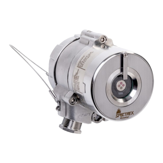
- Page 1 Quick Start Guide 00925-0200-9975, Rev AB August 2023 Spectrex SharpEye 40/40 Series ™ Flame Detectors...
-
Page 2: Table Of Contents
Restrict physical access by unauthorized personnel to protect end users’ assets. This is true for all systems used within the facility. Contents Models............................3 Installing the detector......................... 6 Special conditions for use......................19 Declarations of Conformity.......................21 Reference data........................... 25 Spectrex.net... -
Page 3: Models
The SharpEye 40/40 series comprises the following detectors: SharpEye 40/40C-I The SharpEye 40/40C-I Multispectrum Quad-Sense Flame Detector ™... - Page 4 UV and IR channels that can be used separately or combined. The detector is designed to detect hydrocarbon-based fuel and gas fires. Table 1-1: SharpEye 40/40 Series general technical specifications Spectral response Infrared and ultraviolet bands Response time...
- Page 5 August 2023 Quick Start Guide Table 1-2: Typical current consumption Typical current 40/40C-I 40/40C-LB 40/40D-I 40/40D-LB consumption 40/40C-M 40/40C-L4B 40/40D-M 40/40D-L4B Normal power 60 (1.4) 90 (2.2) 60 (1.4) 90 (2.2) consumption without heater- mA (Watts) Normal power 90 (2.2) 120 (2.9) 90 (2.2) 120 (2.9) consumption...
-
Page 6: Installing The Detector
2.1.2 Duct mount The duct mount (PN 877670) allows flame detection in cases where the detector cannot be installed inside the area. The duct mount limits the cone of vision of the installed detector to 70 degrees horizontal and vertical. Spectrex.net... - Page 7 August 2023 Quick Start Guide 2.1.3 Pole mount Use the pole mount to mount the detector on poles with the following diameters: Table 2-2: Pole mount options Pole diameter Part number 2 in. (50.8 mm) 789260-2 3 in. (76.2 mm) 789260-1 4 in.
- Page 8 The stainless-steel stop plug used to seal the unused conduit will be included in the device. Remember, seal the detector with the stainless-steel plug before use. Refrain from losing the plug in any case A. Detector with two plastic plugs B. Product packaging with stainless-steel plug attachment Spectrex.net...
- Page 9 August 2023 Quick Start Guide 3. Insert location pins on the tilt mount into the openings on detector housing. 4. Thread the holding screw and tighten it. Note To change the detector field of view, release the horizontal and vertical locking screws. 5.
- Page 10 Open the back cover Procedure 1. Loosen the back cover security screw. A. Back cover security screw B. Protective plug 2. Unscrew the back cover. Note The back cover is attached by a security cable. 3. Remove the protective plug. Spectrex.net...
- Page 11 August 2023 Quick Start Guide 2.4 Wire terminals and ground cable NOTICE Improper wiring may damage the detector. Procedure 1. Connect the terminals according to Table 2-3. The terminal details are also on the inside back cover. Figure 2-3: Terminal box Quick Start Guide...
- Page 12 When the alarm/accessories relay wiring option is NC, the relay contact is closed in normal status (de-energized) and open in alarm status (energized). When the alarm/accessories relay wiring option is NO, the relay contact is open in normal status (de-energized) and closed in alarm status (energized). Spectrex.net...
- Page 13 August 2023 Quick Start Guide 2. Use Figure 2-4, Figure 2-5, Figure 2-6, and Figure 2-7 for typical wiring configurations. Figure 2-4: Typical wiring for four-wire controllers A. Controller B. First detector C. Second detector D. Last detector E. Power supply F.
- Page 14 D. Return E. 0-20 mA meter Figure 2-7: Source three-wire A. Detector B. Controller C. Input power: 18-32 VDC D. Return E. 0-20 mA meter Note For additional configuration options, refer to the SharpEye Next Generation 40/40 Series Flame Detectors. Spectrex.net...
- Page 15 August 2023 Quick Start Guide 3. Check the wires for secure mechanical connection and press them neatly against the terminal to prevent them from interfering while closing the back cover. 4. Close the terminal compartment by screwing the back cover on to the housing. Quick Start Guide...
- Page 16 Quick Start Guide August 2023 5. Tighten the back cover security screw. Figure 2-8: Tilt mount Figure 2-9: Closing security screw A. Back cover security screw B. Ground cable connection point 6. Connect the ground cable. Spectrex.net...
- Page 17 August 2023 Quick Start Guide NOTICE When the enclosed threaded plug is utilized in the conduit opening, it must be installed with a minimum thread engagement in order to comply with explosion-proof requirements. For straight threads, a minimum of seven threads must be engaged. For tapered threads, a minimum of five threads must be engaged.
- Page 18 PN 877263 Stainless steel PN 877163 Procedure 1. Place the protective cover on top of the detector. 2. Secure the protective cover by tightening the screw. Note When installing the stainless steel protective cover, the same installation instructions apply. Spectrex.net...
-
Page 19: Special Conditions For Use
August 2023 Quick Start Guide 3 Special conditions for use • Lids securing fasteners shall be property class A4 with a yield stress of 344 N/mm • Units may be painted or fitted with optional accessories; some of which are made of non-metallic material or have a non- metallic coating which could potentially generate an ignition- capable level of electrostatic charge under certain extreme conditions.Therefore, these units shall not be installed in a... - Page 20 For straight threads, a minimum of seven threads must be engaged. For tapered threads, a minimum of five threads must be engaged. Plug and seal the unused conduit connection with the provided conduit plug. Spectrex.net...
-
Page 21: Declarations Of Conformity
August 2023 Quick Start Guide 4 Declarations of Conformity Figure 4-1: SharpEye 40/40C Quick Start Guide... - Page 22 Quick Start Guide August 2023 Spectrex.net...
- Page 23 August 2023 Quick Start Guide Figure 4-2: SharpEye 40/40D Quick Start Guide...
- Page 24 Quick Start Guide August 2023 Spectrex.net...
-
Page 25: Reference Data
To view current SharpEye 40/40 ordering information, specifications, and drawings: Procedure 1. Go to https:// www.spectrex.net/en-us/flame-gas-detectors/flame-detectors/ sharpeye-40-40-next-generation-series-flame-detectors. 2. Select the appropriate flame detector. 3. For installation drawings, click Drawings & Schematics and select the appropriate document. 4. For ordering information, specifications, and dimensional drawings, click Data Sheets &... - Page 26 Quick Start Guide August 2023 Spectrex.net...
- Page 27 August 2023 Quick Start Guide Quick Start Guide...
- Page 28 *00925-0200-9975* Quick Start Guide 00925-0200-9975, Rev. AB August 2023 For more information: Emerson.com/global © 2023 Emerson. All rights reserved. Spectrex is a mark of one of the Emerson family of companies. All other marks are the property of their respective owners.
Need help?
Do you have a question about the SharpEye 40/40 Series and is the answer not in the manual?
Questions and answers