Spectrex SharpEye 40/40 Series Quick Start Manual
Flame detectors
Hide thumbs
Also See for SharpEye 40/40 Series:
- User manual (78 pages) ,
- User manual (88 pages) ,
- Quick start manual (28 pages)

Related Manuals for Spectrex SharpEye 40/40 Series


Summary of Contents for Spectrex SharpEye 40/40 Series
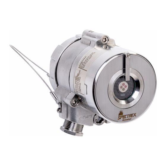
- Page 1 Quick Start Guide 00925-0200-9975, Rev AA May 2021 ™ Spectrex SharpEye 40/40 Series Flame Detectors...
-
Page 2: Table Of Contents
Restrict physical access by unauthorized personnel to protect end users’ assets. This is true for all systems used within the facility. Contents Models............................3 Installing the detector........................6 Special conditions for safe use....................15 Declarations of Conformity......................16 Reference data........................... 18 Spectrex.net... -
Page 3: Models
The detectors are intended for indoor or outdoor use and can be used stand alone or connected to an alarm/automatic extinguishing system. The SharpEye 40/40 series comprises the following detectors: SharpEye 40/40-I ™ The SharpEye 40/40C-I, a multispectrum Quad-sense... - Page 4 20 msec, and features a unique dual sensor with selectable UV and IR channels that can be used separately or combined. The detector is designed to detect hydrocarbon-based fuel and gas fires. Table 1-1: SharpEye 40/40 Series General Technical Specifications Spectral response Infrared and ultraviolet bands...
- Page 5 May 2021 Quick Start Guide CAUTION If the product is used outside of specified limits, this voids the product certification, and our company is not responsible for any incurred warranty expense. Do not open this product, except for the terminal compartment as listed in this document, under any circumstances.
-
Page 6: Installing The Detector
The duct mount (PN 877670) allows flame detection in cases where the detector cannot be installed inside the area. The duct mount limits the cone of vision of the installed detector to 70 degrees horizontal and vertical. For more instructions, refer to the Duct Mount Manual (00809-0600-4975). Spectrex.net... - Page 7 May 2021 Quick Start Guide 2.1.3 Pole mount Use the pole mount to mount the detector on poles with the following diameters: Table 2-2: Pole Mount Options Pole diameter Part number 2 in. (50.8 mm) 789260-2 3 in. (76.2 mm) 789260-1 4 in.
- Page 8 Open the back cover Procedure 1. Loosen the back cover security screw. A. Back cover security screw B. Protective plug 2. Unscrew the back cover. Note The back cover is attached by a security cable. 3. Remove the protective plug. Spectrex.net...
- Page 9 May 2021 Quick Start Guide Wire terminals and ground cable CAUTION Improper wiring may damage the detector. Procedure 1. Connect the terminals according to Table 2-3. The terminal details are also on the inside back cover. Figure 2-1: Terminal Box Quick Start Guide...
- Page 10 0-20 mA (+) 0-20 mA (-) Alarm output (40/40D models) RS485 (+) RS485 (-) Accessory relay - normally open Accessory relay Accessory relay - normally closed 2. Use Figure 2-2, Figure 2-3, Figure 2-4, and Figure 2-5 for typical wiring configurations. Spectrex.net...
- Page 11 May 2021 Quick Start Guide Figure 2-2: Typical Wiring for Four-Wire Controllers A. Controller B. First detector C. Second detector D. Last detector E. Power supply F. Alarm loop G. End of line Figure 2-3: Non-Isolated Sink (Three Wires) Figure 2-4: Sink Four-Wire Quick Start Guide...
- Page 12 5. Tighten the back cover security screw. Figure 2-6: Closing Security Screw A. Back cover security screw B. Ground cable connection point 6. Connect the ground cable. WARNING The terminal temperature may be higher than 185 °F (85 °C). Spectrex.net...
- Page 13 May 2021 Quick Start Guide CAUTION To comply with EMC directive 2014/30/EU and protect against interference caused by radio frequency interference (RFI) and electromagnetic interference (EMI), shield the cable to the detector and ground the detector. Ground the shield at the detector end. Quick Start Guide...
- Page 14 ABS plastic 00975-9000-0020 Stainless steel 00975-9000-0021 Procedure 1. Place the protective cover on top of the detector. 2. Secure the protective cover by tightening the screw. Note When installing the stainless steel protective cover, the same installation instructions apply. Spectrex.net...
-
Page 15: Special Conditions For Safe Use
Flameproof joints are not intended to be repaired. • The SharpEye 40/40 Series Flame Detectors can be fitted with an unmolded (non-encapsulated) end of line (EOL) resistor. Such a resistor can only be fitted into the flameproof "Ex d" compartment as indicated in the instructions. -
Page 16: Declarations Of Conformity
Quick Start Guide May 2021 Declarations of Conformity Figure 4-1: SharpEye 40/40C Spectrex.net... - Page 17 May 2021 Quick Start Guide Figure 4-2: SharpEye 40/40D Quick Start Guide...
-
Page 18: Reference Data
Reference data To view current SharpEye 40/40 ordering information, specifications, and drawings: Procedure 1. Go to https://spectrex.net/en-us/flame-gas-detectors/flame- detectors/40-40-series. 2. Select the appropriate flame detector. 3. For installation drawings, click Drawings and Schematics and select the appropriate document. 4. For ordering information, specifications, and dimensional drawings, click Data Sheets &... - Page 19 May 2021 Quick Start Guide Quick Start Guide...
- Page 20 Quick Start Guide 00925-0200-9975, Rev. AA May 2021 For more information: www.emerson.com © 2021 Emerson. All rights reserved. Spectrex is a mark of one of the Emerson family of companies. All other marks are the property of their respective owners.
Need help?
Do you have a question about the SharpEye 40/40 Series and is the answer not in the manual?
Questions and answers