Table of Contents
Advertisement
Quick Links
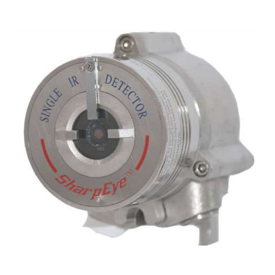
Model 40/40R
Single IR
Flame Detector
User Guide
FM, CSA Approved:
ATEX and IECEx Approved
Class I Div. 1 Groups B, C, D
Ex II 2 GD, EExde IIB+ H2 T5 (75°C)
Class II/III Div. 1 Groups E, F, G
Document ref: TM 40/40R, Rev (1) September 2008
218 Little Falls Rd., Cedar Grove, NJ 07009, USA
Phone: +1 (973) 239 8398
Fax: +1 (973) 239 761
Web-Site: www.spectrex-inc.com; Email:
spectrex@spectrex-inc.com
Advertisement
Table of Contents
Troubleshooting

Related Manuals for Spectrex SharpEye 40/40R


Summary of Contents for Spectrex SharpEye 40/40R
- Page 1 Ex II 2 GD, EExde IIB+ H2 T5 (75°C) Class II/III Div. 1 Groups E, F, G Document ref: TM 40/40R, Rev (1) September 2008 218 Little Falls Rd., Cedar Grove, NJ 07009, USA Phone: +1 (973) 239 8398 Fax: +1 (973) 239 761 Web-Site: www.spectrex-inc.com; Email: spectrex@spectrex-inc.com...
-
Page 3: Warranty
Spectrex, Inc. reserves the right to make changes to any products described herein to improve reliability, function, or design, and reserves the right to revise this document and make changes from time to time in content hereof with no obligation to notify any persons of revisions or changes. -
Page 4: Release History
Release History Date Revision History Prepared by Approved by July 15, 2008 First Release Ian Buchanan Eric Zinn September 23, 2008 Second Release Ian Buchanan Eric Zinn... -
Page 5: About This Guide
About this Guide This guide describes the SharpEye Model 40/40R Single IR Flame Detector and its features and provides instructions on how to install, operate and maintain the detector. This guide includes the following chapters and appendixes: Chapter 1, Introduction, provides a general overview of the product, principles of operation, and performance considerations. -
Page 6: Abbreviations And Acronyms
Abbreviations and Acronyms Abbreviation Meaning ATEX Atmosphere Explosives American Wire Gauge Built In Test Electromagnetic Compatibility End of Line Field of View HART Highway Addressable Remote Transducer- communication protocol Immune at Any Distance IECEx International Electrotechnical Commission Explosion Isopropyl Alcohol Infrared Jet Fuel Latching... -
Page 7: Table Of Contents
Table of Contents Model 40/40R Single IR Flame Detector User Guide ........i Legal Notice ....................iii Warranty ......................iii Release History ....................iv About this Guide ....................v Abbreviations and Acronyms ................vi Introduction ....................1 Overview ....................1 Model and Types .................. - Page 8 Installation Cables ................21 2.5.1 Conduit Installation ................. 21 Installing the Tilt Mount (Part No. 40/40-001) .......... 22 2.6.1 Tilt Mount Specifications ..............23 2.6.2 Tilt Mount Assembly ................ 23 Connecting the Detector ................ 25 2.7.1 Verifying the Detector Wiring ............26 Configuring your Detector ..............
- Page 9 RS-485 Communication Network ............. 55 RS-485 Overview .................. 55 Accessories ....................57 Long Range Fire Simulator ..............57 D.1.1 Unpacking ..................58 D.1.2 Operating Instructions ..............58 D.1.3 Range ................... 59 D.1.4 Charging the Battery ............... 59 D.1.5 Technical Specifications ..............60 Tilt Mount P/N 40/40-001 ..............
- Page 10 List of Figures Figure 1: Field of View ..................8 Figure 2: Indication LED ..................10 Figure 3: Detector with Tilt Mount ............... 22 Figure 4: Tilt Mount Assembly ................23 Figure 5: Tilt Mount Assembly (dimensions in mm and inches) ........ 24 Figure 6: Detector with Cover Removed ...............
- Page 11 List of Tables Table 1: Wiring Options ..................3 Table 2: Fuel Sensitivity Ranges ................8 Table 3: Immunity to False Alarm Sources ............9 Table 4: LED Indications ..................10 Table 5: Available Output Types ................11 Table 6: Detector Status ..................12 Table 7: Output Signals versus Detector State ............
- Page 12 List of Tables...
-
Page 13: Introduction
EExde IIB + H2 T5 (75°C) or T4 (85°C). The SharpEye 40/40R Detectors are designed to operate as a stand-alone unit directly connected to an alarm system or an automatic fire extinguishing system. -
Page 14: Model And Types
SharpEye Single IR Flame Detector User Guide Model and Types The 40/40R is provided in various configurations depending on: Wiring options Temperature ranges Type of cable entries Housing type Required approval The configuration detail is included in the product part number on the product label and takes the form: 40/40R XXXXX, where XXXXX defines the model according to the above requirements. -
Page 15: Table 1: Wiring Options
TM 40/40R, Rev. (1) September 2008 Table 1: Wiring Options Wiring Connections Provided Option Fault Alarm Manual 4-20mA Power Relay Relay RS-485 Sink N.C. N.O. Alarm Fault Manual Relay 4-20mA Power Relay RS-485 N.O., Source N.C. N.C. Alarm Fault Manual Relay 4-20mA Power... -
Page 16: Features And Benefits
SharpEye Single IR Flame Detector User Guide Features and Benefits Single IR Channel: Between 4.4 - 4.6 microns. Built In Test (BIT): Manual and Automatic (see Built-In-Test (BIT) on page 14). Heated Window: Prevents effects of icing, snow, condensation. ... -
Page 17: Heated Optics
TM 40/40R, Rev. (1) September 2008 1.4.2 Heated Optics The SharpEye 40/40 Flame Detector uses heated optics. The heater increases the temperature of the optical surface by 5°F - 8°F (~3°C - 5°C) above the ambient temperature to improve performance in icing, condensation and snow conditions. -
Page 18: Product Certification
SharpEye Single IR Flame Detector User Guide 1.4.5 Product Certification The 40/40R Flame Detectors have the following certifications: ATEX, IECEx, page 6 FM, CSA, page 6 SIL-2 Approved, page 6 EN54-10, page 6 1.4.5.1 ATEX, IECEx The 40/40R Optical Flame Detector is certified to: ... -
Page 19: Performance Considerations
TM 40/40R, Rev. (1) September 2008 This test includes functional test, environmental test, EMI/EMC test and software check. For more details see EN54-10 Report No. TE243256. Performance Considerations This section describes performance aspects of the 40/40R and includes: ... -
Page 20: Cone Of Vision
SharpEye Single IR Flame Detector User Guide Maximum Response Time: 10 sec. Table 2: Fuel Sensitivity Ranges Type Of Fuel Max. Distance ft (m) Gasoline 50 (15) N-Heptane 50 (15) 37 (11) Kerosene 37 (11) Diesel Fuel 37 (11) Alcohol 95% 25 (7.5) 25 (7.5) -
Page 21: False Alarm Prevention
TM 40/40R, Rev. (1) September 2008 1.5.3 False Alarm Prevention To prevent false alarms, the detector will not alarm or react to the radiation sources specified in Table 3. Table 3: Immunity to False Alarm Sources Immunity Radiation Source Distance ft(m) Vehicle headlights (low beam) conforming to 1.7 (0.5) MS53023-1... -
Page 22: Visual Indicators
SharpEye Single IR Flame Detector User Guide 1.5.4 Visual Indicators One 3-color LED indicator is located inside the detector window, as shown in Figure 2. The detector statuses are listed in Table 4. Table 4: LED Indications Detector Status LED color LED mode Fault, BIT Fault Yellow... -
Page 23: Output Signals
TM 40/40R, Rev. (1) September 2008 1.5.5 Output Signals Outputs are available according to the default configuration or the wiring options selected for the detectors. Determine the outputs for your model according to Table 5. The detector incorporates several types of output suitable to different control systems: ... -
Page 24: Detector Status
SharpEye Single IR Flame Detector User Guide 1.5.6 Detector Status The possible detector function statuses are listed in Table 6. A more detailed fault analysis can be seen via HART or RS485. Table 6: Detector Status Status Description Normal Normal operation. Built-In-Test being performed. -
Page 25: Auxiliary Relay As End-Of-Line Resistor
TM 40/40R, Rev. (1) September 2008 The detector will remain in BIT Fault state until it has passed a successful BIT. The Auxiliary Relay can be activated at the Warning level or Alarm level, depending on programmed function. The outputs depend on the wiring options. 1.5.6.1 Optional Latching Alarms are set as non-latching by default. -
Page 26: Built-In-Test (Bit)
SharpEye Single IR Flame Detector User Guide 0-20mA level output Relays and heater operation Processor Watch dog Software Memory Oscillator frequency Response to Fault Indication If a failure is found, the detector indicates by: ... -
Page 27: Table 8: Results Of A Successful Bit
TM 40/40R, Rev. (1) September 2008 1.6.2.2 Automatic BIT The detector automatically performs a BIT every 15 minutes. A successful BIT sequence does not activate any indicator. The results of a successful and unsuccessful BIT are listed in Table 8 and Table 9. -
Page 28: Table 10: Results Of A Successful Manual Bit
SharpEye Single IR Flame Detector User Guide Table 10: Results of a Successful Manual BIT Output Result FAULT relay Wiring options 1, 2, and 4: remains CLOSED (Normal) Wiring options 3 and 5: remains OPEN (Normal) ALARM relay Activated for 3 sec (only when the function Alarm BIT is set to YES) AUXILIARY... -
Page 29: Installing The Detector
Installing the Detector ➣ In this chapter… General Guidelines page 17 Unpacking the Product page 18 Required Tools page 18 Certification Instructions page 20 Installation Cables page 21 Installing the Tilt Mount (Part No. 40/40-001) page 22 Connecting the Detector page 25 Configuring your Detector page 27... -
Page 30: Unpacking The Product
SharpEye Single IR Flame Detector User Guide Aiming the Detector: The detector should be aimed toward the center of the detection zone and have a completely unobstructed view of the protected area. Whenever possible, the detector face should be tilted down at a 45º angle to maximize coverage and prevent accumulation of dust and dirt. - Page 31 TM 40/40R, Rev. (1) September 2008 For wiring, use color-coded conductors or suitable wire markings or labels. 12 to 20 AWG (0.5 mm² to 3.5 mm²) wires may be used for site wiring. The selection of wire gauge should be based on the number of detectors used on the same line and the distance from the control unit, in compliance with specifications (see General Instructions for Electrical Wiring on page 49).
-
Page 32: Certification Instructions
SharpEye Single IR Flame Detector User Guide Certification Instructions Warning: Do not open the detector, even when isolated, when flammable atmosphere present. Use the following certification instructions: The cable entry point may exceed 167°F (75°C). Suitable precautions should be taken when selecting the cable. ... -
Page 33: Installation Cables
TM 40/40R, Rev. (1) September 2008 Installation Cables Follow the following guidelines for the cable installation: All cables to the detector must be well shielded in order to comply with EMC requirements (see Technical Specifications on page 60). Ground the detector to the nearest ground point (not more than 3m from the detector location). -
Page 34: Installing The Tilt Mount (Part No. 40/40-001)
SharpEye Single IR Flame Detector User Guide Installing the Tilt Mount (Part No. 40/40-001) The Tilt Mount enables the detector to be rotated up to 60º in all directions. Figure 3 shows the Detector mounted on the Tilt Mount. Figure 3: Detector with Tilt Mount Installing the Tilt Mount (Part No. -
Page 35: Tilt Mount Specifications
TM 40/40R, Rev. (1) September 2008 2.6.1 Tilt Mount Specifications Table 13: USA Version Item Type Location Tilt Mount 40/40-001 Screw ¼" 20 UNC x ¾" Detector – Holding plate Spring Washer No. ¼" Detector - Holding plate Table 14: European Version Item Type Location... -
Page 36: Figure 5: Tilt Mount Assembly (Dimensions In Mm And Inches)
SharpEye Single IR Flame Detector User Guide Figure 5 shows the Tilt Mount Assembly with dimension in both millimeters and inches. Figure 5: Tilt Mount Assembly (dimensions in mm and inches) ➣ To install the tilt mount and detector: Place the tilt mount in its designated location and secure it with four (4) fasteners through four (4) holes 7 mm in diameter. -
Page 37: Connecting The Detector
TM 40/40R, Rev. (1) September 2008 Connecting the Detector This section describes how to connect the electric cabling to the detector (Figure 6). ➣ To connect the detector to the electrical cables: Disconnect the power. Remove the back cover of the detector by removing four (4) socket head-screws in the cover bolts. -
Page 38: Verifying The Detector Wiring
SharpEye Single IR Flame Detector User Guide Check the wires for secure mechanical connection and press them neatly against the terminal to prevent them from interfering while closing the back cover (Figure 6). Place and secure the detector‟s back cover by screwing the four (4) socket-head-screws in the Cover Bolts (Figure 3). -
Page 39: Configuring Your Detector
You can reprogram the function setup using the RS-485 connection or using the Hart Protocol as follows: Spectrex Host Software: The Spectrex Host Software is for use on a PC or laptop. Refer to Manual TM777050 for programming instructions. The Host software enables you to change the functions. -
Page 40: Alarm Delay
SharpEye Single IR Flame Detector User Guide Heated Optics – Auto Temperature – 20 2.8.1 Alarm Delay The detector is equipped with an Alarm Delay option, which provides programmable time delays with settings at: Antiflare* (default) *The Antiflare mode is selected to prevent false alarms in locations where fast flares may be present. -
Page 41: Function Set-Up
TM 40/40R, Rev. (1) September 2008 2.8.3 Function Set-up You can select the desired functions as detailed in Table 16. Table 16: Functions Function Setting Alarm Latch Yes: Enable Alarm latching. No: Disable Alarm latching (default). Auxiliary Relay** Yes: Activate Auxiliary Relay at Warning level. - Page 42 SharpEye Single IR Flame Detector User Guide Configuring your Detector...
-
Page 43: Operating The Detector
Operating the Detector ➣ In this chapter… Powering Up page 31 Safety Precautions page 32 Testing Procedures page 34 This chapter describes how to power up and test the detector. It also includes some very important safety checks that you should make before operating the detector. -
Page 44: Safety Precautions
Heat Mode Auto Heat On The detector starts heating the window for any temperature below this value (in degrees Celsius). To change the default function, use: P.C with Spectrex software, refer to Manual 777050 for instructions. Safety Precautions... - Page 45 TM 40/40R, Rev. (1) September 2008 Handheld unit, refer to Manual 777060 for instructions. USB cable with 485 converter (1 meter) part number 794079-5. HART Protocol, refer to Manual 777030 for instructions. Safety Precautions...
-
Page 46: Testing Procedures
This section describes the proof testing procedure for proper operation of the detector. The detector can be tested using the Manual Built-in-Test or the Spectrex Fire Simulator - 20/20-312. The detector performs internal test continuously and automatic BIT test every 15 minutes for more details refer to Built-In-Test (BIT) on page 14. -
Page 47: Table 18: Results Of Successful Fire Simulator Test
TM 40/40R, Rev. (1) September 2008 Aim the Spectrex Fire Simulator Model 20/20-312 at the target point of the detector (Figure 14), in a way that the radiation emitted by it directly faces the detector. (See Long Range Fire Simulator on page 57). - Page 48 SharpEye Single IR Flame Detector User Guide Testing Procedures...
-
Page 49: Maintenance And Troubleshooting
This chapter deals with preventive maintenance, describes possible faults in detector operation and indicates corrective measures. Ignoring these instructions may cause problems with the detector and may invalidate the warranty. Whenever a unit requires service, please contact Spectrex or its authorized distributor for assistance. Maintenance... -
Page 50: Periodic Procedures
Serial and tag no. Entries for every maintenance operation performed, including the description of the operation, date and personnel ID. If a unit is sent to Spectrex or a distributor for service, a copy of the maintenance records should accompany it. Maintenance... -
Page 51: Troubleshooting
TM 40/40R, Rev. (1) September 2008 Troubleshooting This section is intended as a guide to correcting problems that may arise during normal operation. Table 19: Troubleshooting Table Problem Cause Corrective Action LEDs Off No power at the Check that the correct power ... - Page 52 SharpEye Single IR Flame Detector User Guide Troubleshooting...
-
Page 53: Appendices
Appendices Appendices... - Page 54 SharpEye Single IR Flame Detector User Guide Appendices...
-
Page 55: A Technical Specifications
Technical Specifications ➣ In this appendix… Electrical Specifications page 43 Mechanical Specifications page 45 Dimensions page 45 Weight page 46 Environmental Specifications page 46 Electrical Specifications Operating 18-32 VDC Voltage Power Without Heated Optic: Consumption Max. 100mA in Standby Max. -
Page 56: Table 20: Contact Ratings
SharpEye Single IR Flame Detector User Guide Electrical Dry Contact Relays Outputs Table 20: Contact Ratings Relay Type Normal Maximum Name Position Ratings Alarm DPST N.O., N.C. 2A at 30 VDC or 0.5A at 250 VAC Auxiliary SPST N.O. 5A at 30 VDC or 250 VAC Fault *... -
Page 57: Mechanical Specifications
TM 40/40R, Rev. (1) September 2008 For more details refer to HART Manual 777030. Communication Network: The detector is equipped with an RS-485 communication link that can be used in installations with computerized controllers. The communications protocol is Modbus compatible. ... -
Page 58: Weight
Single IR Flame Detector User Guide Weight Stainless Steel: 5.5 lb (2.5 Kg) Aluminium: 2.5 lb (1.2 kg) Environmental Specifications The SharpEye 40/40R is designed to withstand harsh environmental conditions. High Temperature Designed to meet MIL-STD-810C, method 501.1 procedure II Operating temperature: +167°F (+75 °C) - Page 59 TM 40/40R, Rev. (1) September 2008 Electromagnetic This product is in conformance with EMC directive Compatibility (EMC) 89/336/EC: Conducted Disturbances: IEC/EN61000-4-6 ESD: IEC/EN61000-4-2 Burst: IEC/EN61000-4-4 Surge: IEC/EN61000-4-5 Immunity to main supply voltage variations: MIL-STD-1275B Radiated Immunity: IEC/EN61000-4-3 ...
- Page 60 SharpEye Single IR Flame Detector User Guide Environmental Specifications...
-
Page 61: B Wiring Instructions
Wiring Instructions ➣ In this appendix… General Instructions for Electrical Wiring page 49 Typical Wiring Configurations page 51 General Instructions for Electrical Wiring Follow the instructions detailed in this section to determine the correct wire gauge to be used for the installation. Use Table 22 to determine the required wire gauge /size for general wiring, such as relay wiring. -
Page 62: Table 23: Wiring Length In Feet (Meter)
SharpEye Single IR Flame Detector User Guide Table 23: Wiring Length in Feet (Meter) Power Number Supply Recommended Wire Diameter (AWG) Range Detectors (VDC) 22-32 22-32 22-32 20-32 20-32 4 and less 20-32 Ft (m) (50) (100) (150) (200) (240) Max. -
Page 63: Typical Wiring Configurations
TM 40/40R, Rev. (1) September 2008 Typical Wiring Configurations This section describes examples of typical wiring configurations. Figure 7: Wiring Terminals Typical Wiring Configurations... -
Page 64: Figure 8: Typical Wiring For 4-Wire Controllers (Using Option 1 Or 2 Wiring)
SharpEye Single IR Flame Detector User Guide Table 24: Wiring Connections Wiring Detector Terminals Option Model 40/40R-1XXXX Fault Relay 0-20mA 0-20mA N.C. Sink Sink 40/40R-2XXXX Fault Relay Alarm Relay 0-20mA N.C. N.C. Source 40/40R-3XXXX Fault Relay Alarm Relay 0-20mA N.O. N.C. -
Page 65: Figure 9: 0-20Ma Wiring (Sink) 4-Wire Connection
TM 40/40R, Rev. (1) September 2008 Figure 9: 0-20mA Wiring (Sink) 4-Wire Connection (for Source version, link Terminals 1 and 8) Figure 10: 0-20mA Wiring (Source) 3-Wire Connection Notes: The detectors are supplied as: Isolated 0-20mA – Sink in wiring option 1. ... - Page 66 SharpEye Single IR Flame Detector User Guide Typical Wiring Configurations...
-
Page 67: Crs-485 Communication Network
247 on the same four (4) wires. When using the RS-485 network, it is possible to read each detector status (FAULT, WARNING, and ALARM) and to initiate a BIT to each detector individually. For more details, consult Spectrex. Figure 11: RS-485 Networking RS-485 Overview... - Page 68 SharpEye Single IR Flame Detector User Guide RS-485 Overview...
-
Page 69: Accessories
Accessories ➣ In this appendix… Long Range Fire Simulator page 57 Tilt Mount P/N 40/40-001 page 60 Weather Protection – P/N 777163 page 61 Laser Detection Coverage Pointer – P/N page 62 777166 Air Shield – P/N 777161 page 62 This appendix describes the accessories that can help you maximize fire detection with the SharpEye flame detector. -
Page 70: Unpacking
SharpEye Single IR Flame Detector User Guide D.1.1 Unpacking Verify that you have received the following contents: Delivery form Fire Simulator with integral batteries Battery charger Storage case D.1.2 Operating Instructions Warning: Do not open the Fire Simulator to charge the batteries or for any other reason in a hazardous area. -
Page 71: Range
TM 40/40R, Rev. (1) September 2008 D.1.3 Range The 40/40R detector will trigger an alarm from a simulator, at a maximum distance of 2.4ft (0.75m). Notes: The minimum distance from the detector is 20 inches (50 cm). At extreme temperatures, there is a 15% maximum reduction in the range. -
Page 72: Technical Specifications
SharpEye Single IR Flame Detector User Guide D.1.5 Technical Specifications Explosion Proof Enclosure: Mechanical AFM (designed to meet) Class I, Division 1 & 2 Groups B, C and D Class II, Division 1 & 2 Groups E, F and G ... -
Page 73: Weather Protection - P/N 777163
TM 40/40R, Rev. (1) September 2008 Weather Protection – P/N 777163 The weather protector protects the detector from different weather conditions, such as snow and rain. Figure 15: Weather Protection Weather Protection – P/N 777163... -
Page 74: Laser Detection Coverage Pointer - P/N 777166
SharpEye Single IR Flame Detector User Guide Laser Detection Coverage Pointer – P/N 777166 The Laser Detection Coverage Pointer evaluates detector coverage on-site. The device is an add-on accessory that enables designers and installers to optimize detector location and assess the actual coverage of installed detectors. -
Page 75: Sil-2 Features
40/40R Optical Flame Detector This appendix details the special conditions to comply with the requirements of EN 61508 for SIL-2. The SharpEye 40/40R shall only be used in low demand mode application, see IEC 61508.4, Chapter 3.5.12. E.1.1 Safety Relevant Parameters Perform the following functional checks of the detector: ... - Page 76 SharpEye Single IR Flame Detector User Guide The 24V power supply must fulfill the requirements for PELV / SELV of EN 60950. The automatic BIT (Built-In-Test) must be activated. The set-up parameters must be verified (as described in Using the 4- 20mA Interface for Alerting on page 64, point 1 and in Using the Alarm Relay Contact for Alerting on page 64, point 1) and the function of the 40/40 Flame Detector (flame detection, function of the 4-20mA...
- Page 77 TM 40/40R, Rev. (1) September 2008 The HART and the RS 485/IrDA interfaces must not be used for the transmission of the safety-related data. 40/40R Optical Flame Detector...
-
Page 78: Technical Support
Fax: +1 (973) 239 7614 Email: spectrex@spectrex-inc.com Web-site: www.spectrex-inc.com Your Local Authorized Distributor: SPECTREX INC. New Jersey (USA) Key Person: President: Mr. Eric Zinn 218 Little Falls Road. Cedar Grove, NJ 07009 +1 (973) 239 8398 +1 (800) 452 2107...
Need help?
Do you have a question about the SharpEye 40/40R and is the answer not in the manual?
Questions and answers