
Related Manuals for Spectrex SharpEye 40/40UFI


Summary of Contents for Spectrex SharpEye 40/40UFI
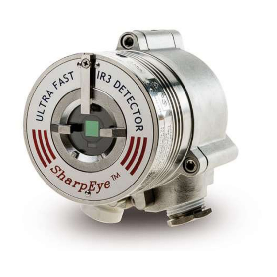
- Page 1 Model 40/40UFI Ultra-Fast IR3 Flame Detector User Guide 8200 Market Blvd, Chanhassen, MN 55317, USA Phone: +1 (973) 239 8398 Website: www.spectrex.net Email: spectrex.csc.rmtna@emerson.com...
- Page 3 “Act of God” which are above and beyond its control. SPECTREX will, upon receipt of any defective product, transportation prepaid, repair or replace it at its sole discretion if found to have been defective when shipped. Said repair or replacement is SPECTREX’S sole liability under this warranty and SPECTREX’S liability shall be limited to repair or replacement of the component found...
-
Page 5: Table Of Contents
Table of Contents Table of Contents .................... v List of Figures ....................ix List of Tables ....................x About this Guide ..................11 Release History ..................12 Glossary and Abbreviations ..............12 Notifications ..................14 Product Overview ..................15 Approvals..................... 15 Model and Types ................... - Page 6 3.1.3 Spacing and Location ..............31 3.1.4 Environment .................. 31 3.1.5 Aiming the Detector ................ 31 Unpacking the Product ................32 3.2.1 Checking the Product Type ............... 32 Required Tools ..................32 Certification Instructions ................ 33 3.4.1 Special Instructions for Safe Use ............33 3.4.2 General Instructions ................
- Page 7 Electrical Specifications ................54 Electrical Input Protection ..............54 Outputs ....................54 A.4.1 Electrical Interface ................54 A.4.2 Electrical Outputs ................55 A.4.3 Heated Optics ................. 56 Approvals..................... 57 A.5.1 Hazardous Area Approvals ............... 57 A.5.2 Functional Approvals ............... 57 Mechanical Specifications ...............
- Page 8 D.1.4 Range ................... 71 D.1.5 Charging the Battery ............... 71 D.1.6 Battery Replacement ............... 72 Technical Specifications ................. 73 D.2.1 General ..................73 D.2.2 Electrical ..................73 D.2.3 Physical ..................73 D.2.4 EMI Compatibility ................74 Tilt Mount .................... 75 Duct Mount ..................
-
Page 9: List Of Figures
List of Figures Figure 1: Field of View ..................24 Figure 2: Indicator LED ..................26 Figure 3: Detector with Tilt Mount ............... 36 Figure 4: Tilt Mount Assembly ................37 Figure 5: Tilt Mount Assembly (dimensions in millimeters and inches) ..... 37 Figure 6: Detector with Cover Removed ............... - Page 10 List of Tables Table 1: Wiring Options ..................17 Table 2: Sensitivity Range Levels ................ 22 Table 3: Fuel Sensitivity Ranges ................23 Table 4: Immunity to False Alarm Sources ............24 Table 5: Welding Immunity Distance ..............25 Table 6: LED Indications ..................25 Table 7: Available Output Types ................
-
Page 11: About This Guide
About this Guide About this Guide This guide describes the SharpEye Model 40/40UFI Ultra-Fast IR3 Flame Detector and its features and provides instructions on how to install, operate, and maintain the detector. Note: This user guide should be read carefully by all individuals who have or will have responsibility for using, maintaining, or servicing the product. -
Page 12: Release History
About this Guide Release History Revision Prepared by Approved by Date History February 2015 First Release Ian Buchanan Eric Zinn June 2015 Second Ian Buchanan Eric Zinn Release November Third Release Ian Buchanan Eric Zinn 2015 January 2016 Fourth Release Ian Buchanan Eric Zinn March 2016... - Page 13 About this Guide Abbreviation/Term Meaning Internet Protocol Isopropyl Alcohol Infrared Refers to the 3 IR sensors in the VID Jet Fuel Light Emitting Diode Serial communications protocol using Master-Slave MODBUS messaging Not Applicable N.C. Normally Closed NFPA National Fire Protection Association Normally Open N.O.
-
Page 14: Notifications
About this Guide Notifications This section explains and exemplifies the usage of warnings, cautions, and notes throughout this guide: Warning: This indicates a potentially hazardous situation that could result in serious injury and/or major damage to the equipment. Caution: This indicates a situation that could result in minor injury and/or damage to the equipment. -
Page 15: Product Overview
Product Overview Product Overview The SharpEye 40/40UFI is a flame detector that utilizes improved IR3 technology to provide state-of-the-art fire protection. The 40/40UFI uses patented digital signal processing to analyze the spectral and dynamic characteristics of the measured infrared radiation, to identify fire events with exceptional sensitivity and extreme immunity to false alarms. -
Page 16: Model And Types
Product Overview (–55°C ≤ Ta ≤ +85°C) Model and Types The 40/40UFI Flame Detector is provided in various configurations depending on: • Wiring options • Temperature ranges • Type of cable entries • Housing material type • Required approval The configuration detail is included in the product part number on the product label and takes the form: 40/40UFI-XXXXX, where XXXXX defines the model according to the above requirements. -
Page 17: Table 1: Wiring Options
Product Overview Table 1 describes the wiring options in detail. Table 1: Wiring Options Wiring Connections Provided Option Fault Alarm Analog 0–20mA Power Relay Relay RS-485 HART Output Sink N.C. N.O. Alarm Fault Analog Relay 0–20mA Power Relay RS-485 HART Output N.O., Source... -
Page 18: Features And Benefits
This section describes the 40/40 principles of operation. 2.4.1 Hydrocarbon Fire Detection The SharpEye 40/40UFI Detector is designed to detect flames in which carbon dioxide (CO ) is produced in the combustion process. These include all hydrocarbon flames, as well as other types of flames and burning materials such as wood or alcohol. -
Page 19: Heated Optics
The detector does not react when exposed to non- fire radiation sources. The SharpEye 40/40UFI also includes an additional IR sensor, sensitive to a different band within the emission peak of hot CO . This sensor’s signal is compared to those of the other 3, thereby increasing sensitivity for some types of flames, such as gas flames. -
Page 20: Product Certification
Product Overview 2.4.5 Product Certification The 40/40UFI Flame Detectors have the following certifications: • ATEX, IECEx, page 20 • FM, CSA, page 20 • SIL-2, page 21 • EN54-10, page 21 • Inmetro (UL), page 21 • TR CU/EAC, page 21 2.4.5.1 ATEX, IECEx The 40/40UFI Flame Detector is certified to:... - Page 21 Product Overview 2.4.5.3 SIL-2 The 40/40UFI Flame Detector is approved per SIL-2 requirement per IEC 61508.4, Chapter 3.5.12. The alert condition according to SIL-2 can be implemented by: • Alert signal via 0–20mA current loop • Alert signal via alarm relay and fault relay •...
-
Page 22: Performance Considerations
Product Overview (–55°C ≤ Ta ≤ +75°C) For more details, see TR CU certificate No. ТC RU C- US.МЮ62.В.05536. Performance Considerations This section describes performance aspects of the 40/40UFI. 2.5.1 Detection Sensitivity Detection sensitivity is the maximum distance at which the detector reliably detects a specific size of fire and typical type of fuel (standard fire). -
Page 23: Cone Of Vision
Product Overview • The baseline fire refers to n-heptane 1ft /0.1m and is defined as 100% sensitivity. • For fuel fire – standard pan fire size: 1ft /0.1m • For gas flame – 30”/0.75m high, 10”/0.25m width plume fire. • Maximum Response Time: 2 sec for 1x1ft n-heptane fire at 131ft/40m •... -
Page 24: False Alarm Prevention
Product Overview Figure 1: Field of View 2.5.3 False Alarm Prevention To prevent false alarms, the detector will not alarm or react to the radiation sources specified in Table 4. Table 4: Immunity to False Alarm Sources Immunity Radiation Source Distance ft/m Indirect or reflected sunlight Vehicle headlights (low beam) conforming to... -
Page 25: Visual Indicators
Product Overview Radiation heater, 1000W with fan Quartz lamp (1000W) >3/1 Mercury vapor lamp Grinding metal Lit cigar >1/0.3 Lit cigarette >1/0.3 Match, wood, stick including flare up >13/4 Notes: IAD = Immune at Any Distance • All sources are chopped from 0–20Hz •... -
Page 26: Output Signals
Product Overview Indicator LED Figure 2: Indicator LED 2.5.5 Output Signals Outputs are available according to the default configuration or the wiring options selected for the 40/40UFI detector. Determine the outputs for your model according to Table 7. The detector incorporates several types of output suitable to different control systems: •... -
Page 27: Detector Status
Product Overview Fault Relay 40/40UFI – Options The relay is N.C. energized 1XXXX, 2XXXX, and 4XXXX 40/40UFI – Options The relay is N.O. energized 3XXXX and 5XXXX 0–20mA 40/40UFI – Option Sink with the HART protocol, Current Output 1XXXX (can be changed to Source – see Figure 9, Figure 10, and Figure 11) 40/40UFI –... -
Page 28: Auxiliary Relay As End-Of-Line
Product Overview 20mA BIT Fault Yellow Warning at 16mA BIT Fault Alarm at Constant 20mA BIT Fault Fault Yellow The alarm outputs are activated while alarm conditions exist and will stop approximately 5 seconds after the fire is no longer detected. The alarm state can be optionally latched via programmed function (default is non-latched). -
Page 29: Continuous Feature Test
Product Overview • Continuous Feature Test, page 29 • Built-In-Test (BIT), page 29 2.6.1 Continuous Feature Test During normal operation, the detector tests itself continuously and indicates a fault if a failure is found. This type of test complies with SIL-2 requirements. The detector continuously tests: •... -
Page 30: Table 10: Results Of A Successful Bit
Product Overview 2.6.3.1 How the BIT Operates • The detector's status remains unchanged if the result of a BIT is the same as the current status (normal or BIT fault). • The detector’s status changes (from normal to BIT fault or vice versa) if the BIT differs from the current status. -
Page 31: Installing The Detector
Installing the Detector Installing the Detector General Guidelines To ensure optimal performance and an efficient installation, consider the following guidelines: 3.1.1 Sensitivity To determine the level of sensitivity, consider the following: • Size of fire at the required distance to be detected •... -
Page 32: Unpacking The Product
Installing the Detector Installation should comply with NFPA 72E or any other local and international regulations and standards, as applicable to flame detectors and installation of Ex approved products. Unpacking the Product Upon receipt of your detector, verify that you have received the following contents: •... -
Page 33: Certification Instructions
Installing the Detector For wiring, use color-coded conductors or suitable wire markings or labels. 12– 20AWG / 0.5–3.5mm² wires may be used for site wiring. The selection of wire gauge should be based on the number of detectors used on the same line and the distance from the control unit, in compliance with specifications (see General Instructions for Electrical Wiring on page 61). -
Page 34: General Instructions
Installing the Detector 3.4.2 General Instructions • The cable entry point may exceed 167°F/75°C. Suitable precautions should be taken when selecting the cable. • The equipment may be used with flammable gases and vapors with apparatus groups IIA, IIB, and IIC: •... -
Page 35: Conduit Installation
Installing the Detector 3.5.1 Conduit Installation The conduit used for the cabling must comply with the following: • To avoid water condensation or water in the detector, install the detector with the conduits placed downward to include drain holes. • When using the optional tilt mount, use flexible conduits for the last portion connecting to the detector. -
Page 36: Installing The Tilt Mount
Installing the Detector Installing the Tilt Mount The tilt mount (P/N 40/40-001) enables the detector to be rotated up to 60º in all directions. Figure 3 shows the detector mounted on the tilt mount. Figure 3: Detector with Tilt Mount SharpEye™... -
Page 37: Tilt Mount Assembly
Installing the Detector 3.6.1 Tilt Mount Assembly Figure 4 shows the tilt mount assembly. Tilt holding plate Tilt mount Horizontal locking screw Vertical locking screw Detector holding plate Figure 4: Tilt Mount Assembly Figure 5 shows the tilt mount assembly with dimensions in both millimeters and inches. -
Page 38: Connecting The Detector
Installing the Detector To install the tilt mount and detector: Place the tilt mount in its designated location and secure it with 4 fasteners through 4 holes 7mm in diameter. Use the 4 screws and spring washers according to the kit. Note: Removing the detector for maintenance purpose does not require the tilt mount to be removed. -
Page 39: Verifying The Detector Wiring
Installing the Detector Terminal chamber Terminals Internal earth terminal Earth terminal Detector holding screw Conduit/cable inlet Figure 6: Detector with Cover Removed Connect the wires to the required terminals on the terminal board according to the wiring diagram (Figure 6) and Table 13. Connect the grounding (earth) wire to the ground (earth) screw outside the detector (earth terminal). -
Page 40: Table 13: Model 40/40Ufi Wiring Options
Installing the Detector For relay connection options see Figure 9. Table 13 describes the function of each terminal for all the wiring options. Table 13: Model 40/40UFI Wiring Options Wire Option 1 Option 2 Option 3 Option 4 Option 5 Terminal Default +24VDC... -
Page 41: Configuring Your Detector
• USB RS-485 Harness Kit (P/N 794079): The USB RS-485 Harness Kit with RS-485/USB converter, used with the SPECTREX host software, enables you to connect to any available PC or laptop to re-configure settings or perform diagnostics on all 40/40 series flame detectors. -
Page 42: Sensitivity
Installing the Detector • Automatic BIT – Yes • Auxiliary Relay – No • EOL – No • Heated Optics – Auto • Temperature – 41°F/5°C 3.8.1 Sensitivity The detector offers 4 sensitivity settings. The settings refer to an n-heptane or gasoline fire of 1ft²/0.1m², from low sensitivity of 66ft/20m to 300ft/90m. -
Page 43: Address Setup
Installing the Detector 3.8.3 Address Setup The detector provides up to 247 addresses that can be changed with the RS-485 communication link or the HART protocol. 3.8.4 Function Setup You can select the desired functions as detailed in Table 15. Table 15: Functions Function Setting... -
Page 45: Operating The Detector
Operating the Detector Operating the Detector This chapter describes how to power up and test the detector. It also includes some very important safety checks that you should complete before operating the detector. Powering Up This section describes how to power up the detector. Follow these instructions carefully to obtain optimal performance from the detector over its lifecycle: To turn on the detector: Turn on the power. -
Page 46: Default Functions Settings
Testing Procedures This section describes the proof testing procedure for proper operation of the detector. The detector can be tested with SPECTREX Flame Simulator FS-1100. The detector performs internal tests continuously and automatic BIT tests every 15 minutes. For more details refer to Built-In-Test (BIT) on page 29. -
Page 47: Testing With Flame Simulator Model Fs-1100
Power up the system and wait up to 60 seconds for the detector to turn to a normal state. The Power LED turns on. Aim the SPECTREX Flame Simulator Model FS-1100 at the target point of the detector (Figure 14), such that the radiation emitted by it is facing directly towards the detector. -
Page 49: Maintenance And Troubleshooting
This chapter deals with preventive maintenance, describes possible faults in detector operation and indicates corrective measures. Ignoring these instructions may cause problems with the detector and may invalidate the warranty. Whenever a unit requires service, please contact SPECTREX or its authorized distributor for assistance. Maintenance This section describes the basic maintenance steps that should be taken to keep the detector in good working condition. -
Page 50: Keeping Maintenance Records
• Entries for every maintenance operation performed, including a description of the operation, date, and personnel ID If a unit is sent to SPECTREX or a distributor for service, a copy of the maintenance records should accompany it. Troubleshooting This section is a guide to correct problems which may happen during normal operation. - Page 51 Maintenance and Troubleshooting TM40/40UFI Rev. (Ai), February 2019...
-
Page 53: Appendix A: Specifications
Specifications Appendix A: Specifications Technical Specifications Spectral Response 3 IR Bands Detection Range Fuel ft/m Fuel ft/m (at highest n-Heptane 300/90 Kerosene 205/62 sensitivity setting Gasoline 300/90 Ethanol 95% 185/55 for 1ft /0.1m Diesel Fuel 205/62 Methanol 160/48 fire) 205/62 IPA (Isopropyl 185/55 Alcohol) -
Page 54: Electrical Specifications
Specifications Electrical Specifications • Operating Voltage: 18–32VDC • Power Consumption: Table 19 Table 19: Electrical Specifications Operating Status Without 0– Voltage Outputs 20mA Power Normal 1.61W 1.56W Consumption Normal when heater on 2.28W 2.16W (Max. 24VDC) Alarm 2.64W 2.28W Alarm when heater on 3.24W 2.88W Maximum Current... -
Page 55: Electrical Outputs
Specifications • Option 1: Power, RS-485, Analog Output 0–20mA (Sink), Fault I Relay (N.C.), Alarm Relay, (N.O.) (see Figure 6). • Option 2: Power, RS-485, Analog Output 0–20mA (Source) and HART protocol, Fault Relay (N.O.), Alarm Relay, (N.O.), (N.C.). • Option 3: Power, RS-485, Analog Output 0–20mA (Source) and HART protocol, Fault Relay (N.O.), Alarm Relay (N.O., N.C.). -
Page 56: Heated Optics
Specifications A.4.2.4 HART Protocol The HART protocol is a digital communication signal at a low level on top of the 0–20mA. This bi-directional field communication protocol is used to communicate between intelligent field instruments and the host system. HART is available in wiring options 2 and 3. -
Page 57: Approvals
Specifications Approvals A.5.1 Hazardous Area Approvals • FM, CSA Class I Div. 1 Groups B, C, and D; Class II/III Div. 1 Groups E, F, and G • ATEX, IECEx Ex II 2G D Ex db eb op is IIC T4 Gb Ex tb op is IIIC T96°C Db (–55°C ≤... -
Page 58: Mechanical Specifications
4” x 4.6” x 6.18” / 101.6 x 117 x 157 mm A.6.6 Weight • Stainless Steel: 6.1lb/2.8kg • Aluminum: 2.8lb/1.3kg Environmental Specifications The SharpEye 40/40UFI is designed to withstand harsh environmental conditions. A.7.1 High Temperature • Designed to meet MIL-STD-810C, Method 501.1 Procedure II • Operating temperature: +167°F/+75 °C •... -
Page 59: Humidity
Specifications A.7.3 Humidity • Designed to meet MIL-STD-810C, Method 507.1, Procedure IV • Relative humidity of up to 95% for the operational temperature range A.7.4 Salt Fog • Designed to meet MIL-STD-810C, Method 509.1, Procedure I • Exposure to a 5% salt solution fog for 48 hours A.7.5 Dust •... - Page 60 Specifications Caution: To fully comply with EMC directive 2014/30/EU and protect against interference caused by RFI and EMI, the cable to the detector must be shielded and the detector must be grounded. The shield should be grounded at the detector end. SharpEye™...
-
Page 61: Appendix B: Wiring Instructions
Wiring Instructions Appendix B: Wiring Instructions General Instructions for Electrical Wiring Follow the instructions detailed in this section for determining the correct wire gauge to be used for the installation. Use Table 23 to determine the required wire gauge/size for general wiring, such as relay wiring. -
Page 62: Calculation Formula
Wiring Instructions Calculation Formula Use the following formula to calculate minimum wire gauge per wire length between the power supply (controller) and the detector, considering the number of detectors on the same power line, where: • L = Actual wire length between the detector and the power supply •... -
Page 63: Typical Wiring Configurations
Wiring Instructions Typical Wiring Configurations This section describes examples of typical wiring configurations. Figure 7: Wiring Terminals Table 25: Wiring Connections Wiring Detector Terminals Option Model 40/40UFI- Fault Relay 0–20mA 0–20mA 1XXXX (N.C.) (Sink) (Sink) 40/40UFI- Fault Relay Alarm Relay 0–20mA 2XXXX (N.C.) -
Page 64: Figure 8: Typical Wiring For 4 Wire Controllers (Using Option 1 Or 2 Wiring)
Wiring Instructions Figure 8: Typical Wiring for 4 Wire Controllers (Using Option 1 or 2 Wiring) Figure 9: 0–20mA Wiring Option 1 (Sink 4-Wire) - Default SharpEye™ Ultra-Fast IR3 Flame Detector User Guide... -
Page 65: Figure 10: 0-20Ma Wiring Option 1 (Converted To Source 3-Wire)
Wiring Instructions Figure 10: 0–20mA Wiring Option 1 (Converted to Source 3-Wire) Figure 11: 0–20mA Wiring Option 1 (Non-isolated Sink 3-Wire) TM40/40UFI Rev. (Ai), February 2019... -
Page 66: Figure 12: 0-20Ma Wiring Option 2 And 3
Wiring Instructions Figure 12: 0–20mA Wiring Option 2 and 3 Notes: There are no 0–20mA outputs in wiring options 4 and 5. • Source 3-Wire available with the HART Protocol • SharpEye™ Ultra-Fast IR3 Flame Detector User Guide... -
Page 67: Appendix C: Rs-485 Communication Network
247 on the same 4 wires. When using the RS-485 network, it is possible to read each detector status (FAULT, WARNING, and ALARM) and to initiate a BIT for each detector individually. For more details, contact SPECTREX. Figure 13: RS-485 Networking TM40/40UFI Rev. (Ai), February 2019... -
Page 69: Appendix D: Accessories
Accessories Appendix D: Accessories This appendix describes the accessories that can help you maximize fire detection with the SharpEye Ultra-Fast IR3 Flame Detector. Flame Simulator FS-1100 The Flame Simulator FS-1100 is designed specifically for use with SharpEye Flame Detectors. The Flame Simulator emits IR radiation in a unique sequential pattern corresponding to and recognizable by the detector as fire, which allows the detectors to be tested under simulated fire conditions without the associated risks of an open flame. -
Page 70: Unpacking
Accessories D.1.2 Unpacking Verify that you have received the following contents: • Delivery form • Flame simulator with integral battery • Tool keys • User manual • FAT forms • EU declaration • Storage case D.1.3 Operating Instructions Warning: Do not open the flame simulator to charge the batteries or for any other reason in a hazardous area. -
Page 71: Range
Accessories D.1.4 Range Table 26: Sensitivity Ranges Sensitivity Detection Range (ft/m) Standard Test Range (ft/m) 1 (Low) 66/20 13/4 133/40 26/8 200/60 40/12 4 (High) 300/90 50/15 Notes: The minimum distance from the detector is 20”/50cm. • At extreme temperatures, there is a 15% maximum reduction in •... -
Page 72: Battery Replacement
Unscrew the battery back cover (Item 4) counterclockwise. Unscrew the locking disc (Item 3) clockwise. Pull out the battery from the flame simulator. Insert the new battery pack in the simulator housing. Use only SPECTREX battery pack, P/N 380004. Screw on the locking disc (Item 3). -
Page 73: Technical Specifications
Accessories Note: For more information refer to TM380002. Technical Specifications D.2.1 General • Temperature Range: –4°F to +122ºF / –20ºC to +50ºC • Vibration Protection: 1g (10–50Hz) D.2.2 Electrical • Power: 14.8V (4 X 3.7V rechargeable lithium-ion battery) • Max. Current: 4A •... -
Page 74: Emi Compatibility
Accessories D.2.4 EMI Compatibility Table 27: Immunity Tests Immunity Tests Title Basic Standard Level to be tested Electrostatic IEC 61000-4-2 6kV/8kV contact/air Discharge (ESD) Radiated IEC 61000-4-3 20V/m (80MHz–1GHz) Electromagnetic 10V/m (1.4–2GHz) Field 3V/m (2.0–2.7GHz) Conducted IEC 61000-4-6 10Vrms (150kHz–80MHz) Disturbances Immunity to MIL-STD-1275B... -
Page 75: Tilt Mount
Accessories Tilt Mount The tilt mount (P/N 40/40-001) provides accurate directional selection for optimum area coverage. Figure 16: Tilt Mount TM40/40UFI Rev. (Ai), February 2019... -
Page 76: Duct Mount
Accessories Duct Mount The duct mount (P/N 777670) is suitable for use with the SharpEye 40/40 Series Optical Flame Detector 40/40UFI, for both the aluminum and St.St. enclosure. The duct mount allows flame detection in areas where high temperatures exist or where the detector cannot be installed inside the area. -
Page 77: Weather Cover
Accessories Weather Cover The weather cover (P/N 777163) protects the detector from different weather conditions, such as snow and rain. Figure 18: Weather Cover TM40/40UFI Rev. (Ai), February 2019... -
Page 78: Air Shield
Accessories Air Shield The air shield (P/N 777650) is suitable for use with the SharpEye 40/40 Series Optical Flame Detector 40/40UFI, for both the aluminum and St.St. enclosures. Optical flame detectors are often used in highly polluted or dirty areas that force maintenance personnel to access the detector frequently in order to clean its optical window. -
Page 79: Appendix E: Sil-2 Features
SIL-2 Features Appendix E: SIL-2 Features 40/40UFI Flame Detector This appendix details the special conditions for compliance with the requirements of EN 61508 for SIL 2. The 40/40UFI Flame Detector can only be used in low or high demand mode applications. -
Page 80: Guidelines For Configuring, Installing, Operating, And Service
SIL-2 Features E.1.2 Guidelines for Configuring, Installing, Operating, and Service The alert conditions according to SIL 2 can be implemented by an: • Alert signal via 20mA current loop • Alert signal via alarm relay and the fault relay • Alert signal via analog output interface. - Page 81 SIL-2 Features E.1.2.3 Using the Alarm Relay Contact for Alerting • The following parameters should be set: • Automatic BIT Test = on • Connected to N.C. contact of alarm relay terminals • Connected to fault relay terminals • The relay contacts (“alarm” and “faulty relay”) must be protected with a fuse rated at 0.6 of the nominal specified relay contact current.
-
Page 82: Appendix F: End Of Line Resistor
End of Line Resistor Appendix F: End of Line Resistor The 40/40 series can be equipped with an EOL resistor inside the flameproof 'd' terminal compartment. The EOL resistor can be situated in the rear part which is Ex e or Ex d , depending on the application. -
Page 84: Technical Support
Technical Support For technical assistance or support, contact: 8200 Market Blvd Chanhassen, MN 55317 Phone: +1 (973) 239 8398 Email: spectrex@spectrex.net Website: spectrex.csc.rmtna@emerson.com...
Need help?
Do you have a question about the SharpEye 40/40UFI and is the answer not in the manual?
Questions and answers