Spectrex SharpEye 40/40 Series User Manual
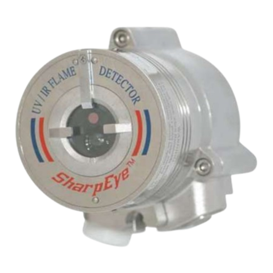
Uv/ir flame detector
Hide thumbs
Also See for SharpEye 40/40 Series:
- User manual (78 pages) ,
- Quick start manual (20 pages) ,
- Quick start manual (28 pages)
Table of Contents
Troubleshooting

Related Manuals for Spectrex SharpEye 40/40 Series


Summary of Contents for Spectrex SharpEye 40/40 Series
- Page 1 40/40 Series UV/IR Flame Detector Models 40/40L, LB and 40/40L4, L4B User Guide 8200 Market Blvd, Chanhassen, MN 55317, USA Phone: +1 (973) 239 8398 Website: www.spectrex.net Email: spectrex.csc.rmtna@emerson.com...
- Page 3 “Act of God” which are above and beyond its control. SPECTREX will, upon receipt of any defective product, transportation prepaid, repair or replace it at its sole discretion if found to have been defective when shipped. Said repair or replacement is SPECTREX’S sole liability under this warranty and SPECTREX’S liability shall be limited to repair or replacement of the component found...
-
Page 5: Table Of Contents
Table of Contents Table of Contents .................... v List of Figures ....................ix List of Tables ....................x About this Guide ..................11 Release History ..................12 Glossary and Abbreviations ..............12 Notifications ..................15 Product Overview ..................17 Approvals..................... 17 Model and Types ................... - Page 6 3.1.3 Spacing and Location ..............37 3.1.4 Environment .................. 37 3.1.5 Aiming the Detector ................ 38 Unpacking the Product ................38 3.2.1 Checking the Product Type ............... 38 Required Tools ..................38 Certification Instructions ................ 39 3.4.1 Special Instructions for Safe Use ............39 3.4.2 General Instructions ................
- Page 7 Electrical Specifications ................58 A.2.1 Electrical Input Protection ..............58 Outputs ....................58 A.3.1 Electrical Interface ................58 A.3.2 Electrical Outputs ................59 A.3.3 HART Protocol ................60 A.3.4 Communication Network ..............60 A.3.5 Heated Optics ................. 60 Approvals..................... 61 A.4.1 Hazardous Area Approvals ...............
- Page 8 D.1.2 Unpacking ..................74 D.1.3 Operating Instructions ..............74 D.1.4 Range ................... 75 D.1.5 Charging the Battery ............... 75 D.1.6 Battery Replacement ............... 76 D.1.7 Technical Specifications ..............77 Tilt Mount .................... 78 Duct Mount ..................79 Weather Cover ..................80 Air Shield .....................
-
Page 9: List Of Figures
List of Figures Figure 1: Horizontal Field of View ................ 26 Figure 2: Vertical Field of View ................27 Figure 3: Indicator LED ..................29 Figure 4: Detector with Tilt Mount ............... 42 Figure 5: Tilt Mount Assembly ................43 Figure 6: Tilt Mount Assembly (dimensions in millimeters and inches) ..... - Page 10 List of Tables Table 1: Wiring Options ..................19 Table 2: Detector Versions ................. 19 Table 3: Fuel Sensitivity Ranges ................26 Table 4: Immunity to False Alarm Sources ............27 Table 5: LED Indications ..................28 Table 6: Available Output Types ................30 Table 7: Detector Status ..................
-
Page 11: About This Guide
About this Guide About this Guide This guide describes the SharpEye Model 40/40L, LB, L4, L4B (UV/IR) Flame Detector and its features and provides instructions on how to install, operate, and maintain the detector. Note: This user guide should be read carefully by all individuals who have or will have responsibility for using, maintaining, or servicing the product. -
Page 12: Release History
About this Guide Release History Date Revision History Prepared by Approved by February 2015 First Release Eric Zinn Buchanan June 2015 Second Release Eric Zinn Buchanan November Third Release Eric Zinn 2015 Buchanan January 2016 Fourth Release Eric Zinn Buchanan March 2016 Fifth Release Eric Zinn... - Page 13 About this Guide Abbreviation/Term Meaning Analog Video Video values are represented by a scaled signal ATEX Atmosphere Explosives American Wire Gauge Built-In-Test Complementary Metal-Oxide Semiconductor image CMOS sensor Each component is represented by a number Digital Video representing a discrete quantization Digital Signal Processing Electromagnetic Compatibility Electromagnetic Interference...
- Page 14 About this Guide Abbreviation/Term Meaning Unified Coarse Thread Volts Alternating Current SharpEye™ 40/40L, LB and 40/40L4, L4B User Guide...
-
Page 15: Notifications
About this Guide Notifications This section explains and exemplifies the usage of warnings, cautions, and notes throughout this guide: Warning: This indicates a potentially hazardous situation that could result in serious injury and/or major damage to the equipment. Caution: This indicates a situation that could result in minor injury and/or damage to the equipment. -
Page 17: Product Overview
SPECTREX product warranty. The SharpEye 40/40 detector is designed to operate as a stand-alone unit directly connected to an alarm system or an automatic fire extinguishing system. -
Page 18: Model And Types
Product Overview Ex II 2G D Ex db eb op is IIC T4 Gb Ex tb op is IIIC T106°C Db (–55°C ≤ Ta ≤ +85°C) Model and Types The 40/40L, LB, L4, L4B UV/IR flame detectors are provided in various configurations depending on: •... -
Page 19: Table 1: Wiring Options
Product Overview Note: Aluminum housing is not available in the FM version. Table 1 describes the wiring options in detail. Table 1: Wiring Options Wiring Connections Provided Option Fault Alarm Manual 0–20mA Power Relay Relay RS-485 HART Sink N.C. N.O. Alarm Fault Manual... -
Page 20: Features And Benefits
Product Overview For example, product number 40/40L, LB, L4, L4B-321SC has the following options: • Detector Version: UV/IR, IR at 2.8µm, without BIT • Wiring Option: 3 (Power, Manual BIT, RS-485, 0–20mA [Source] with the HART protocol, Fault Relay [N.O.], Alarm Relay [N.O., N.C.]) •... -
Page 21: Principles Of Operation
Product Overview Principles of Operation This section describes the 40/40L, LB, L4, and L4B principles of operation. 2.4.1 Detection Principles The Model 40/40L, LB, L4, L4B Flame Detector is an electronic device designed to sense the occurrence of fire and flames and subsequently activate an alarm or an extinguishing system directly or through a control circuit. -
Page 22: Heated Optics
Product Overview 2.4.2 Heated Optics The SharpEye 40/40 Flame Detector uses heated optics. The heater increases the temperature of the optical surface by 5–8°F / ~3–5°C above the ambient temperature to improve performance in ice, condensation, and snow conditions. The heated optics can be set to one of the following: •... - Page 23 Product Overview • Inmetro (UL), page 24 • TR CU/EAC, page 24 2.4.5.2 ATEX, IECEx The 40/40L, LB, L4, L4B Flame Detector is certified to: ATEX per SIRA 07ATEX1250X and IECEx per IECEx SIR 07.0085X Ex II 2G D Ex db eb op is IIC T4 Gb Ex tb op is IIIC T96°C Db (–55°C ≤...
- Page 24 Product Overview 2.4.5.4 SIL-2 (TÜV) (Models 40/40LB and L4B only) The 40/40LB, L4B Flame Detectors are approved per SIL-2 requirement per IEC 61508.4, Chapter 3.5.12. The alert condition according to SIL-2 can be implemented by: • Alert signal via 0–20mA current loop •...
-
Page 25: Performance Considerations
Product Overview For more details, see TR CU certificate No. ТC RU C- US.МЮ62.В.05536. Performance Considerations This section describes performance aspects of the 40/40L, LB, L4, and L4B. 2.5.1 Detection Sensitivity Detection sensitivity is the maximum distance at which the detector reliably detects a specific size of fire and typical type of fuel (standard fire). -
Page 26: Cone Of Vision
Product Overview Table 3: Fuel Sensitivity Ranges Max. Distance (ft/m) Type of Fuel L/LB L4/L4B Gasoline 50/15 93/28 N-Heptane 50/15 93/28 43/13 60/18 37/11 70/21 Kerosene 37/11 70/21 Diesel Fuel 37/11 70/21 Polypropylene 33/10 60/18 Hydrogen 33/10 Methane 26/8 60/18 Ethanol 95% 25/7.5 57/17... -
Page 27: False Alarm Prevention
Product Overview • Vertical: +50° (down), –45° (up) Figure 2: Vertical Field of View 2.5.3 False Alarm Prevention To prevent false alarms, the detector will not alarm or react to the radiation sources specified in Table 4. Table 4: Immunity to False Alarm Sources Immunity Radiation Source Distance ft/m... -
Page 28: Visual Indicators
Product Overview Bright colored clothing, including red and safety orange Electronic flash (180 watt-seconds minimum output) Movie light, 625W quartz DWY lamp (Sylvania S.G.-55 >6.5/2 or equivalent) Blue-green dome light conforming to M251073-1 Flashlight (MX 991/U) Radiation heater, 3000W Radiation heater, 1000W with fan Quartz lamp (1000W) 12/4 Mercury vapor lamp... -
Page 29: Output Signals
Product Overview Indicator LED Figure 3: Indicator LED 2.5.5 Output Signals Outputs are available according to the default configuration or the wiring options selected for the 40/40L, LB, L4, and L4B detectors. Determine the outputs for your model according to Table 6. The detector incorporates several types of output suitable to different control systems: •... -
Page 30: Detector Status
Product Overview Table 6: Available Output Types Output Type Version Detector Status Alarm Relay 40/40L, LB, L4, L4B – The relay is N.O. Options 1XXXX, 4XXXX, and 5XXXX 40/40L, LB, L4, L4B – The relay is N.O. and N.C. Options 2XXXX and 3XXXX Auxiliary Relay 40/40L, LB, L4, L4B –... -
Page 31: Table 8: Output Signals Versus Detector State
Product Overview In each state, the detector activates different outputs, as specified in Table 8. Table 8: Output Signals Versus Detector State Detector Alarm Auxiliary Fault State Indicator Mode Relay Relay Relay output Normal Green Warning 16mA Alarm Constant 20mA Latched Constant 20mA... -
Page 32: Auxiliary Relay As End-Of-Line
Product Overview Notes: The auxiliary relay is available only in Models with suffix – 4XXXX • and 5XXXX The 0–20mA is available only in Models with suffix – 1XXXX, • 2XXXX, and 3XXXX 2.5.7 Auxiliary Relay as End-of-Line The auxiliary relay can be used as End-of-Line in models with suffix – 4XXXX and 5XXXX only. -
Page 33: Built-In-Test (Bit)
Product Overview • Correcting the fault The fault indications remain until the detector’s power is removed. The fault indications return if the fault is still found when power is restored. 2.6.3 Built-In-Test (BIT) The detector’s Built-In-Test (BIT) also checks the following: •... -
Page 34: Table 9: Results Of A Successful Bit
Product Overview Table 10, and the BIT is automatically executed every 1 minute. This sequence continues until a successful BIT occurs, when the detector resumes normal operation. Table 9: Results of a Successful BIT Output Result Fault Relay Wiring options 1, 2, and 4: remains closed Wiring options 3 and 5: remains open 0–20mA Wiring options 1, 2, and 3: normal (4mA) -
Page 35: Table 11: Results Of A Successful Manual Bit
Product Overview Table 11: Results of a Successful Manual BIT Output Result Fault Relay Wiring options 1, 2, and 4: remains Closed (Normal) • Wiring options 3 and 5: remains Open (Normal) • Alarm Relay Activated for 3 sec (only when the function alarm BIT is set to Yes) Auxiliary For wiring options 4 and 5: is activated for 3 sec (only... -
Page 37: Installing The Detector
Installing the Detector Installing the Detector This chapter provides basic guidelines for installing the detector. It does not attempt to cover all of the standard practices and codes of installation. Rather, it emphasizes specific points of consideration and provides some general rules for qualified personnel. -
Page 38: Aiming The Detector
Installing the Detector 3.1.5 Aiming the Detector • The detector should be aimed toward the center of the detection zone and have a completely unobstructed view of the protected area. • Whenever possible, the detector face should be tilted down at a 45º angle to maximize coverage and prevent accumulation of dust and dirt. -
Page 39: Certification Instructions
Installing the Detector Table 13: Tools Tool Function Comments Hex key 3/16” Open and close detector Part of the kit cover (for wiring) Hex key 1/4” Mount the detector on the tilt Part of the kit mount Flat screwdriver Connect ground terminal Standard tool Flat screwdriver Connect wires to the terminal... -
Page 40: General Instructions
Installing the Detector • Gaps, ic, should not be modified to be any larger, and lengths, L, should not be modified to be any shorter than the values shown in the table above. • Units may be painted or fitted with optional accessories, some of which are made of a non-metallic material or have a non-metallic coating which could potentially generate an ignition-capable level of electrostatic charge under certain extreme conditions. -
Page 41: Installation Cables
Installing the Detector • If the equipment is likely to come into contact with aggressive substances, then it is the responsibility of the user to take suitable precautions that prevent it from being adversely affected, thus ensuring that the type of protection provided by the equipment is not compromised: •... -
Page 42: Installing The Tilt Mount
Installing the Detector Installing the Tilt Mount The tilt mount (P/N 40/40-001) enables the detector to be rotated up to 60º in all directions. Figure 4 shows the detector mounted on the tilt mount. Figure 4: Detector with Tilt Mount SharpEye™... -
Page 43: Tilt Mount Assembly
Installing the Detector 3.6.1 Tilt Mount Assembly Figure 5 shows the tilt mount assembly. Tilt holding plate Tilt mount Horizontal locking screw Vertical locking screw Detector holding plate Figure 5: Tilt Mount Assembly Figure 6 shows the tilt mount assembly with dimensions in both millimeters and inches. -
Page 44: Connecting The Detector
Installing the Detector To install the tilt mount and detector: Place the tilt mount in its designated location and secure it with 4 fasteners through 4 holes 7mm in diameter. Use the 4 screws and spring washers according to the kit. Note: Removing the detector for maintenance purpose does not require the tilt mount to be removed. -
Page 45: Figure 7: Detector With Cover Removed
Installing the Detector Terminal chamber Terminals Internal earth terminal Earth terminal Detector holding screw Conduit/cable inlet Figure 7: Detector with Cover Removed Connect the wires to the required terminals on the terminal board according to the wiring diagram (Figure 7) and Table 14. Connect the grounding (earth) wire to the ground (earth) screw outside the detector (earth terminal). -
Page 46: Verifying The Detector Wiring
Installing the Detector 3.7.1 Verifying the Detector Wiring The detector has 5 output wiring options within the Exde integral terminal section of the enclosure. There are 12 terminals labeled 1–12. Table 14 describes the function of each terminal for all the wiring options. Table 14: Model 40/40L, LB, L4, and L4B Wiring Options Wire Option 1... -
Page 47: Configuring Your Detector
• USB RS-485 Harness Kit (P/N 794079): The USB RS-485 Harness Kit with RS-485/USB converter, used with the SPECTREX host software, enables you to connect to any available PC or laptop to re-configure settings or perform diagnostics on all 40/40 series flame detectors. -
Page 48: Alarm Delay
Installing the Detector • Auxiliary Relay – No • Automatic BIT – Yes • Alarm BIT – No • Auxiliary BIT – No • EOL – No • Heated Optics – Auto • Temperature – 41°F/5°C 3.8.1 Alarm Delay The detector is equipped with an alarm delay option, which provides programmable time delays with settings at: •... -
Page 49: Heated Optics
Installing the Detector No: Activate Auxiliary Relay at Alarm level • (default). Automatic BIT Yes: Perform automatic (default). • No: No BIT. • Alarm BIT Yes: Successful Manual BIT activates the Alarm • Relay for approximately 3 seconds (default). No: Successful Manual BIT does not activate the •... -
Page 51: Operating The Detector
Operating the Detector Operating the Detector This chapter describes how to power up and test the detector. It also includes some very important safety checks that you should complete before operating the detector. Powering Up This section describes how to power up the detector. Follow these instructions carefully to obtain optimal performance from the detector over its lifecycle: To turn on the detector: Turn on the power. -
Page 52: Default Functions Settings
Testing Procedures This section describes the proof testing procedure for proper operation of the detector. The detector can be tested with the Manual BIT or the SPECTREX FS- 1200 Flame Simulator. The detector performs internal tests continuously and automatic BIT tests every 15 minutes. -
Page 53: Automatic Bit Test
Power up the system and wait up to 60 seconds for the detector to turn to a normal state. The Power LED turns on. Aim the SPECTREX Flame Simulator Model FS-1200 at the target point of the detector (Figure 15), such that the radiation emitted by it is facing directly towards the detector. -
Page 54: Table 17: Results Of Successful Flame Simulator Test
Operating the Detector Table 17: Results of Successful Flame Simulator Test Component Action Notes 0–20mA Turn to 20mA For a few seconds and then returns to Alarm Relay Activated For a few seconds and then returns to Normal Auxiliary Relay Activated For a few seconds and then returns to Normal... -
Page 55: Maintenance And Troubleshooting
This chapter deals with preventive maintenance, describes possible faults in detector operation and indicates corrective measures. Ignoring these instructions may cause problems with the detector and may invalidate the warranty. Whenever a unit requires service, please contact SPECTREX or its authorized distributor for assistance. Maintenance This section describes the basic maintenance steps that should be taken to keep the detector in good working condition. -
Page 56: Keeping Maintenance Records
• Entries for every maintenance operation performed, including a description of the operation, date, and personnel ID If a unit is sent to SPECTREX or a distributor for service, a copy of the maintenance records should accompany it. Troubleshooting This section is a guide to correct problems which may happen during normal operation. -
Page 57: Appendix A: Specifications
Specifications Appendix A: Specifications A.1 Technical Specifications 40/40L-LB UV:0.185–0.260µm IR:2.5–3.0µm Spectral Response 40/40L4-L4B UV:0.185–0.260µm IR:4.4–4.6µm Fuel ft/m Fuel ft/m 40/40L-LB Detection Range Gasoline 50/15 Hydrogen 33/10 (at highest sensitivity n-Heptane 50/15 Methane 26/8 setting for 1ft /0.1m LPG* 43/13 Ethanol 95% 25/7.5 pan fire) 37/11... -
Page 58: A.2 Electrical Specifications
Specifications A.2 Electrical Specifications • Operating Voltage: 18–32VDC • Power Consumption: Table 19 Table 19: Electrical Specifications Operating Status Without Voltage Outputs 0–20mA Power Normal 1.61W 1.56W Consumption Normal when heater on 2.28W 2.16W (Max. 24VDC) Alarm 2.64W 2.28W Alarm when heater on 3.24W 2.88W Maximum Current... -
Page 59: Electrical Outputs
Specifications • Option 1: Power, RS-485, 0–20mA (Sink), Fault I Relay (N.C.), Alarm Relay, (N.O.) (see Figure 7). • Option 2: Power, RS-485, 0–20mA (Source) and HART protocol, Fault Relay (N.O.), Alarm Relay, (N.O.), (N.C.). • Option 3: Power, RS-485, 0–20mA (Source) and HART protocol, Fault Relay (N.O.), Alarm Relay (N.O., N.C.). -
Page 60: Hart Protocol
Specifications A.3.3 HART Protocol The HART protocol is a digital communication signal at a low level on top of the 0–20mA. This bi-directional field communication protocol is used to communicate between intelligent field instruments and the host system. HART is available in wiring options 2 and 3. -
Page 61: A.4 Approvals
Specifications A.4 Approvals A.4.1 Hazardous Area Approvals • FM, CSA Class I Div. 1 Groups B, C, and D; Class II/III Div. 1 Groups E, F, and G • ATEX, IECEx Ex II 2G D Ex db eb op is IIC T4 Gb Ex tb op is IIIC T96°C Db (–55°C ≤... -
Page 62: Enclosure
Specifications A.5.1 Enclosure • Stainless Steel 316 • Aluminum, heavy duty copper free (less than 1%), red epoxy enamel finish A.5.2 Water and Dust Tight • NEMA 250 type 6p. • IP 66 and IP 67 per EN 60529 A.5.3 Electronic Modules •... -
Page 63: Humidity
Specifications A.6.3 Humidity • Designed to meet MIL-STD-810C, Method 507.1, Procedure IV • Relative humidity of up to 95% for the operational temperature range A.6.4 Salt Fog • Designed to meet MIL-STD-810C, Method 509.1, Procedure I • Exposure to a 5% salt solution fog for 48 hours A.6.5 Dust •... -
Page 64: Electromagnetic Compatibility (Emc)
Specifications A.6.8 Electromagnetic Compatibility (EMC) Table 22: Electromagnetic Compatibility (EMC) Test Standard Level Per Electrostatic Discharge ESD IEC 61000-4-2 EN 50130-4 EN 50130-4 Radiated EM Field IEC 61000-4-3 EN 50130-4 Electrical Fast Transients IEC 61000-4-4 EN 50130-4 Surge IEC 61000-4-5 EN 50130-4 Conducted Disturbances IEC 61000-4-6... -
Page 65: Appendix B: Wiring Instructions
Wiring Instructions Appendix B: Wiring Instructions B.1 General Instructions for Electrical Wiring Follow the instructions detailed in this section for determining the correct wire gauge to be used for the installation. Use Table 23 to determine the required wire gauge/size for general wiring, such as relay wiring. - Page 66 Wiring Instructions • L = Actual wire length between the detector and the power supply • N = Number of detectors per loop • R = Resistance of wire per 100m (see Table 23) • V = Voltage drop on the wire Calculate the voltage drop on the wire as follows: V = 2L x R x N x 0.2A 20+V = Minimum required voltage of the power supply...
-
Page 67: B.2 Typical Wiring Configurations
Wiring Instructions B.2 Typical Wiring Configurations This section describes examples of typical wiring configurations. Figure 8: Wiring Terminals TM40/40L Rev. (Ag), February 2019... -
Page 68: Figure 9: Typical Wiring For 4 Wire Controllers (Using Option 1 Or 2 Wiring)
Wiring Instructions Table 25: Wiring Connections Wiring Detector Terminals Option Model 40/40L, LB, Fault Relay 0–20mA 0–20mA L4, L4B- (N.C.) (Sink) (Sink) 1XXXX 40/40L, LB, Fault Relay Alarm Relay 0–20mA L4, L4B- (N.C.) (N.C.) (Source) 2XXXX 40/40L, LB, Fault Relay Alarm Relay 0–20mA L4, L4B-... -
Page 69: Figure 10: 0-20Ma Wiring Option 1 (Sink 4-Wire) - Default
Wiring Instructions Figure 10: 0–20mA Wiring Option 1 (Sink 4-Wire) - Default Figure 11: 0–20mA Wiring Option 1 (Converted to Source 3-Wire) TM40/40L Rev. (Ag), February 2019... -
Page 70: Figure 12: 0-20Ma Wiring Option 1 (Non-Isolated Sink 3-Wire)
Wiring Instructions Figure 12: 0–20mA Wiring Option 1 (Non-isolated Sink 3-Wire) Figure 13: 0–20mA Wiring Option 2 and 3 (Source 3-Wire available with the HART Protocol) Note: There are no 0–20mA outputs in wiring options 4 and 5. SharpEye™ 40/40L, LB and 40/40L4, L4B User Guide... -
Page 71: Appendix C: Rs-485 Communication Network
247 on the same 4 wires. When using the RS-485 network, it is possible to read each detector status (FAULT, WARNING, and ALARM) and to initiate a BIT for each detector individually. For more details, contact SPECTREX. Figure 14: RS-485 Networking TM40/40L Rev. (Ag), February 2019... -
Page 73: Appendix D: Accessories
Accessories Appendix D: Accessories This appendix describes the accessories that can help you maximize fire detection with the SharpEye UV/IR Flame Detector. D.1 Flame Simulator FS-1200 The Flame Simulator FS-1200 is designed specifically for use with SharpEye flame detectors. The FS-1200 includes a halogen lamp that emits UV and IR energy. This energy is accumulated by a reflector directed towards the detector, which allows the detectors to be tested under simulated fire conditions without the associated risks of an open flame. -
Page 74: Unpacking
Accessories D.1.2 Unpacking Verify that you have received the following contents: • Delivery form • Flame simulator with integral battery • Battery charger • Tool keys • User manual • FAT forms • EU declaration • Storage case D.1.3 Operating Instructions Warning: Do not open the flame simulator to charge the batteries or for any other reason in a hazardous area. -
Page 75: Range
Accessories D.1.4 Range Table 26: Sensitivity Ranges Detector Types Detector Sensitivity Setting Maximum Testing (ft/m) Distance (ft/m) 40/40L-LB 50/15 20/6 40/40L4-L4B 93/28 8/2.5 Notes: The minimum distance from the detector is 20”/50cm. • At extreme temperatures, there is a 15% maximum reduction in •... -
Page 76: Battery Replacement
Unscrew the battery back cover (Item 4) counterclockwise. Unscrew the locking disc (Item 3) clockwise. Pull out the battery from the flame simulator. Insert the new battery pack in the simulator housing. Use only SPECTREX battery pack, P/N 380004. Screw on the locking disc (Item 3). -
Page 77: Technical Specifications
Accessories D.1.7 Technical Specifications Temperature Range: –4°F to +122ºF / –20ºC to General • +50ºC Vibration Protection: 1g (10–50Hz) • Power: 14.8V (4 X 3.7V rechargeable lithium-ion Electrical • battery) Max. Current: 4A • Battery Capacity: 2.2AH • Charging Time: 2A at 2hr •... -
Page 78: D.2 Tilt Mount
Accessories D.2 Tilt Mount The tilt mount (P/N 40/40-001) provides accurate directional selection for optimum area coverage. Figure 17: Tilt Mount SharpEye™ 40/40L, LB and 40/40L4, L4B User Guide... -
Page 79: D.3 Duct Mount
Accessories D.3 Duct Mount The duct mount (P/N 777670) is suitable for use with the SharpEye 40/40 Series Optical Flame Detectors 40/40L, LB, L4 & L4B, for both the aluminum and st.st. enclosure. The duct mount allows flame detection in areas where high temperatures exist or where the detector cannot be installed inside the area. -
Page 80: D.4 Weather Cover
Accessories D.4 Weather Cover The weather cover (P/N 777163) protects the detector from different weather conditions, such as snow and rain. Figure 19: Weather Cover SharpEye™ 40/40L, LB and 40/40L4, L4B User Guide... -
Page 81: D.5 Air Shield
Accessories D.5 Air Shield The air shield (P/N 777650) is suitable for use with the SharpEye 40/40 Series Optical Flame Detectors 40/40L, LB, L4 & L4B, for both the aluminum and st.st. enclosures. Optical flame detectors are often used in highly polluted or dirty areas that force maintenance personnel to access the detector frequently in order to clean its optical window. -
Page 82: Appendix E: Sil-2 Features
Appendix E: SIL-2 Features E.1 40/40LB, L4B Flame Detectors This appendix details the special conditions for compliance with the requirements of EN 61508 for SIL 2. The 40/40LB, L4B Flame Detectors can only be used in low demand mode applications. See IEC 61508.4, Chapter 3.5.12. E.1.1 Safety Relevant Parameters Perform the following functional checks of the detector every 30 days:... - Page 83 • The following allowed output current must be supervised with an accuracy of ± 5%: • Normal State = 4mA • Warning State = 16mA • Alarm State = 20mA • The receiving device must be programmed to indicate a fault condition when current levels reach overcurrent or undercurrent.
-
Page 84: Appendix F: End Of Line Resistor
Appendix F: End of Line Resistor The 40/40 series can be equipped with an EOL resistor inside the flameproof 'd' terminal compartment. The EOL resistor can be situated in the rear part which is Ex e or Ex d , depending on the application. -
Page 88: Technical Support
Technical Support For technical assistance or support, contact: 8200 Market Blvd Chanhassen, MN 55317 Phone: +1 (973) 239 8398 Email: spectrex.csc.rmtna@emerson.com Website: www.spectrex.net...
Need help?
Do you have a question about the SharpEye 40/40 Series and is the answer not in the manual?
Questions and answers